EP1097771A2 - Canal de guidage dans un embarreur - Google Patents
Canal de guidage dans un embarreur Download PDFInfo
- Publication number
- EP1097771A2 EP1097771A2 EP00123412A EP00123412A EP1097771A2 EP 1097771 A2 EP1097771 A2 EP 1097771A2 EP 00123412 A EP00123412 A EP 00123412A EP 00123412 A EP00123412 A EP 00123412A EP 1097771 A2 EP1097771 A2 EP 1097771A2
- Authority
- EP
- European Patent Office
- Prior art keywords
- shells
- supports
- pivot
- pivots
- guiding channel
- Prior art date
- Legal status (The legal status is an assumption and is not a legal conclusion. Google has not performed a legal analysis and makes no representation as to the accuracy of the status listed.)
- Withdrawn
Links
Images


Classifications
-
- B—PERFORMING OPERATIONS; TRANSPORTING
- B23—MACHINE TOOLS; METAL-WORKING NOT OTHERWISE PROVIDED FOR
- B23Q—DETAILS, COMPONENTS, OR ACCESSORIES FOR MACHINE TOOLS, e.g. ARRANGEMENTS FOR COPYING OR CONTROLLING; MACHINE TOOLS IN GENERAL CHARACTERISED BY THE CONSTRUCTION OF PARTICULAR DETAILS OR COMPONENTS; COMBINATIONS OR ASSOCIATIONS OF METAL-WORKING MACHINES, NOT DIRECTED TO A PARTICULAR RESULT
- B23Q7/00—Arrangements for handling work specially combined with or arranged in, or specially adapted for use in connection with, machine tools, e.g. for conveying, loading, positioning, discharging, sorting
-
- B—PERFORMING OPERATIONS; TRANSPORTING
- B23—MACHINE TOOLS; METAL-WORKING NOT OTHERWISE PROVIDED FOR
- B23B—TURNING; BORING
- B23B13/00—Arrangements for automatically conveying or chucking or guiding stock
- B23B13/12—Accessories, e.g. stops, grippers
- B23B13/123—Grippers, pushers or guiding tubes
Definitions
- the present invention relates to a device for coupling to respective supports elements that form the guiding channel of a bar feeder.
- bar feeders have a guiding channel which is formed by two stacked longitudinal elements (hereinafter termed half-shells for convenience in description) which have mutually opposite semicircular slots which, by moving the half-shells toward each other, form a channel along which the bar pusher slides.
- a dedicated feeder introduces a bar in the slot of the lower half-shell; after the closure of the guiding channel by way of the arrangement of the upper half-shell in contact with the lower half-shell, the bar is pushed toward the lathe by the bar pusher.
- the half-shells are replaced with others having slots whose dimensions correspond to the requirements.
- the aim of the present invention is to provide a device which allows to solve the drawbacks of conventional systems, i.e., allows a simpler and more rapid replacement of the half-shells in bar feeders.
- an object of the present invention is to provide a structure which is simple, easy to provide in practice, effective in operation, and having a relatively low cost.
- a device for coupling to respective supports half-shells that form a guiding channel of a bar feeder characterized in that said half-shells are provided with pivots having a diametrical pin which are suitable to engage, in a bayonet-like fashion, respective seats of said supports, said couplings having elastic means for detachably retaining said half-shells on their respective supports.
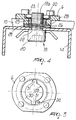
- 1 designates the footing which supports the two half-shells 2 and 3 that form the guiding channel 4 for the bar to be fed.
- the half-shells 2 and 3 are detachably fixed in respective seats 5 and 8 of the first and second collars 6 and 9, which are fixed to the footing 1 and to supporting brackets 10 by means of the screws 7 and 11.
- the brackets 10 are rigidly coupled to a supporting shaft 12 which lies parallel and laterally to the upper half-shell 3 and is rotatably articulated to the footing 1 about an axis 13 which is parallel to the guiding channel 4.
- the upper half-shell 3 is raised with respect to the lower one 2 by virtue of suitable actuators, which turn the upper half-shell 3 so that it rotates about the axis 13 of the shaft 12.
- the half-shells 2 and 3 are each composed of a beam 14 which has a U-shaped cross-section and inside which an insert 15 is provided, said insert being made of a material capable of damping vibrations and absorbing the noise produced during machining.
- Elements 16 are embedded in the material of the insert 15 and define, in the position in which the half-shells 2 and 3 are adjacent one another, walls 17 of the bar guiding channel 4.
- each device 18 is constituted by a cylindrical pivot 19 which has a cylindrical hexagonal socket head 20.
- Each cylindrical pivot 19 is guided in a seat 21 formed in the insert 15 of the half-shells 2 and 3 from the inside outwards, through a hole 22 of the beams 14 that constitute the half-shells.
- pivot 19 proximate to the end that lies opposite the head 20, there is a cylindrical pin 23 which passes diametrically through the pivot 19.
- a calibrated spacer ring 25 In a central position, on the stem 24 of the pivot 19, between the pin 23 and the head 20, a calibrated spacer ring 25, two Belleville spring washers 26, and the thickness of the beam 14 of the half-shell are sequentially assembled and closed in a pack.
- the pivot 19a of the coupling devices of the lower half-shell 2 differs from the upper one 19b only in the central hole 27, which allows the passage of lubricant from the footing 1 into the guiding channel 4.
- the first and second collars 6 and 9 surround, in the face that is directed toward the half-shell, an opening 28 adapted to accommodate the spacer ring 25 for centering the pivot 19 and a seat 29 adapted to receive the Belleville spring washers 26.
- an annular seat 30 which is provided with two diametrically arranged recesses 31 to allow the passage of the diametrical cylindrical pin 23.
- a stroke limit locator stud 32 is arranged in the annular seat 30 that is adjacent to one of the two recesses 31, so that once the pin 23 has been inserted through the recesses 31, it can be turned only in one direction, in the annular seat 30, until abutment occurs with the stud 32, in order to ensure completion of the assembly operation.
- Retention of the half-shells 2 and 3 is achieved due to the compression of the elastic means, i.e., of the Belleville spring washers 26, whose free height is greater than the height of the seat 29 in order to clamp the wall of the beam 14 against the head 20 of the pivots 19.
- the elastic means i.e., of the Belleville spring washers 26
- Removal of the half-shells 2 and 3 is performed by turning in the opposite direction the heads 20 of the pivots 19 until the angular position of the recesses 31 is reached.
- a substantial feature of the described device is that the operator can reload the feeder more rapidly than allowed by the systems currently in use, so as to optimize guiding of the bar to be machined, reducing its vibration and obtaining benefits in the machining of the parts and in the execution times of assembly and disassembly.
Landscapes
- Engineering & Computer Science (AREA)
- Mechanical Engineering (AREA)
- Turning (AREA)
- Snaps, Bayonet Connections, Set Pins, And Snap Rings (AREA)
Applications Claiming Priority (2)
| Application Number | Priority Date | Filing Date | Title |
|---|---|---|---|
| ITBO990590 | 1999-11-03 | ||
| IT1999BO000590A IT1311128B1 (it) | 1999-11-03 | 1999-11-03 | Dispositivo per l' attacco rapido ai rispettivi supporti deglielementi che formano il canale di guida in un caricatore di barre. |
Publications (2)
| Publication Number | Publication Date |
|---|---|
| EP1097771A2 true EP1097771A2 (fr) | 2001-05-09 |
| EP1097771A3 EP1097771A3 (fr) | 2002-05-29 |
Family
ID=11344320
Family Applications (1)
| Application Number | Title | Priority Date | Filing Date |
|---|---|---|---|
| EP00123412A Withdrawn EP1097771A3 (fr) | 1999-11-03 | 2000-11-02 | Canal de guidage dans un embarreur |
Country Status (4)
| Country | Link |
|---|---|
| EP (1) | EP1097771A3 (fr) |
| JP (1) | JP2001191201A (fr) |
| KR (1) | KR20010070182A (fr) |
| IT (1) | IT1311128B1 (fr) |
Cited By (3)
| Publication number | Priority date | Publication date | Assignee | Title |
|---|---|---|---|---|
| ITMI20090755A1 (it) * | 2009-05-04 | 2010-11-05 | Cucchi Pietro Spa | Introduttore di barre con elementi di guida sostituibili |
| ITMO20110189A1 (it) * | 2011-07-28 | 2013-01-29 | Top Automazioni S R L | Apparato per alimentare un tornio con un prodotto da lavorare |
| IT201900020799A1 (it) * | 2019-11-11 | 2021-05-11 | Cucchi Blt S R L | Introduttore o caricatore di barre da tornire per alimentare un tornio, e procedimento per sostituire le ganasce di tale introduttore o caricatore di barre. |
Families Citing this family (1)
| Publication number | Priority date | Publication date | Assignee | Title |
|---|---|---|---|---|
| JP7683918B2 (ja) * | 2021-07-30 | 2025-05-27 | 株式会社アルプスツール | 棒材支持装置 |
Family Cites Families (1)
| Publication number | Priority date | Publication date | Assignee | Title |
|---|---|---|---|---|
| IT221591Z2 (it) * | 1991-01-31 | 1994-07-23 | Pietro Cucchi & C | Guida perfezionata per caricatori di barre in torni |
-
1999
- 1999-11-03 IT IT1999BO000590A patent/IT1311128B1/it active
-
2000
- 2000-11-01 KR KR1020000064529A patent/KR20010070182A/ko not_active Withdrawn
- 2000-11-02 EP EP00123412A patent/EP1097771A3/fr not_active Withdrawn
- 2000-11-02 JP JP2000335562A patent/JP2001191201A/ja not_active Withdrawn
Cited By (3)
| Publication number | Priority date | Publication date | Assignee | Title |
|---|---|---|---|---|
| ITMI20090755A1 (it) * | 2009-05-04 | 2010-11-05 | Cucchi Pietro Spa | Introduttore di barre con elementi di guida sostituibili |
| ITMO20110189A1 (it) * | 2011-07-28 | 2013-01-29 | Top Automazioni S R L | Apparato per alimentare un tornio con un prodotto da lavorare |
| IT201900020799A1 (it) * | 2019-11-11 | 2021-05-11 | Cucchi Blt S R L | Introduttore o caricatore di barre da tornire per alimentare un tornio, e procedimento per sostituire le ganasce di tale introduttore o caricatore di barre. |
Also Published As
| Publication number | Publication date |
|---|---|
| EP1097771A3 (fr) | 2002-05-29 |
| ITBO990590A0 (it) | 1999-11-03 |
| ITBO990590A1 (it) | 2001-05-03 |
| IT1311128B1 (it) | 2002-03-04 |
| KR20010070182A (ko) | 2001-07-25 |
| JP2001191201A (ja) | 2001-07-17 |
Similar Documents
| Publication | Publication Date | Title |
|---|---|---|
| KR920008766B1 (ko) | 축상 절삭공구용 연결장치 | |
| US6786478B2 (en) | Locating assembly having an extendable clamping finger | |
| US7837247B2 (en) | Gripper with central support | |
| KR101008853B1 (ko) | 유압척 | |
| KR960003538B1 (ko) | 나사절삭기 척조립체 | |
| US10632544B2 (en) | Chuck | |
| KR101838916B1 (ko) | 동파이프 확관기 | |
| US5070592A (en) | Spindle unit of a machine tool in which tools changing is available | |
| CN107735200A (zh) | 便携式管车床和方法 | |
| KR20090106230A (ko) | 선반용 자동배출식 척 | |
| EP0390342B1 (fr) | Mécanisme de raccordement | |
| KR101577461B1 (ko) | 자동 선반의 소재 조임력 조절장치 | |
| US20260084225A1 (en) | Hole saw arbor having an adjustable connection mechanism | |
| KR101758780B1 (ko) | 철도차량의 모터 감속기 베어링 분해 지그 | |
| EP1097771A2 (fr) | Canal de guidage dans un embarreur | |
| US6974287B2 (en) | Tool clamping device | |
| JPH0573522B2 (fr) | ||
| US6241261B1 (en) | Chuck | |
| US6543204B2 (en) | Screw-tightening spindle fitted with a removable chuck | |
| US6179303B1 (en) | Device for accomodating a tool or a support element in a machine tool or a spindle | |
| US7458299B2 (en) | Centering device for the guided transfer of bars from a feeder to a lathe | |
| US20080060490A1 (en) | Modular tool carrier for boring machine | |
| US3767217A (en) | Variable chuck | |
| US5524910A (en) | Independent chuck jaw insert having a registration surface enabling locking at a specific position | |
| US4376398A (en) | Bar feed |
Legal Events
| Date | Code | Title | Description |
|---|---|---|---|
| PUAI | Public reference made under article 153(3) epc to a published international application that has entered the european phase |
Free format text: ORIGINAL CODE: 0009012 |
|
| AK | Designated contracting states |
Kind code of ref document: A2 Designated state(s): AT BE CH CY DE DK ES FI FR GB GR IE IT LI LU MC NL PT SE TR |
|
| AX | Request for extension of the european patent |
Free format text: AL;LT;LV;MK;RO;SI |
|
| PUAL | Search report despatched |
Free format text: ORIGINAL CODE: 0009013 |
|
| AK | Designated contracting states |
Kind code of ref document: A3 Designated state(s): AT BE CH CY DE DK ES FI FR GB GR IE IT LI LU MC NL PT SE TR |
|
| AX | Request for extension of the european patent |
Free format text: AL;LT;LV;MK;RO;SI |
|
| 17P | Request for examination filed |
Effective date: 20021031 |
|
| AKX | Designation fees paid |
Designated state(s): CH DE ES FR GB IT LI |
|
| RBV | Designated contracting states (corrected) |
Designated state(s): CH DE ES FR GB IT LI |
|
| GRAP | Despatch of communication of intention to grant a patent |
Free format text: ORIGINAL CODE: EPIDOSNIGR1 |
|
| STAA | Information on the status of an ep patent application or granted ep patent |
Free format text: STATUS: THE APPLICATION HAS BEEN WITHDRAWN |
|
| 18W | Application withdrawn |
Effective date: 20050620 |