EP1097773A1 - Verfahren vor Vorrichtung zur Funkenerosionsbearbeitung - Google Patents
Verfahren vor Vorrichtung zur Funkenerosionsbearbeitung Download PDFInfo
- Publication number
- EP1097773A1 EP1097773A1 EP00122962A EP00122962A EP1097773A1 EP 1097773 A1 EP1097773 A1 EP 1097773A1 EP 00122962 A EP00122962 A EP 00122962A EP 00122962 A EP00122962 A EP 00122962A EP 1097773 A1 EP1097773 A1 EP 1097773A1
- Authority
- EP
- European Patent Office
- Prior art keywords
- tool
- voltage
- phase
- during
- current
- Prior art date
- Legal status (The legal status is an assumption and is not a legal conclusion. Google has not performed a legal analysis and makes no representation as to the accuracy of the status listed.)
- Granted
Links
- 238000003754 machining Methods 0.000 title claims abstract description 62
- 238000000034 method Methods 0.000 title claims abstract description 39
- 230000008569 process Effects 0.000 title description 7
- 150000002500 ions Chemical class 0.000 claims abstract description 47
- 230000003628 erosive effect Effects 0.000 claims abstract description 35
- 239000012530 fluid Substances 0.000 claims abstract description 32
- 238000001514 detection method Methods 0.000 claims description 12
- 230000000694 effects Effects 0.000 claims description 10
- 230000007423 decrease Effects 0.000 claims description 8
- 230000004913 activation Effects 0.000 claims description 4
- 238000001228 spectrum Methods 0.000 claims description 4
- 230000003247 decreasing effect Effects 0.000 claims description 2
- 238000009830 intercalation Methods 0.000 claims 1
- 238000009760 electrical discharge machining Methods 0.000 abstract 1
- 238000005868 electrolysis reaction Methods 0.000 description 26
- 239000007788 liquid Substances 0.000 description 8
- 230000037452 priming Effects 0.000 description 7
- 238000010586 diagram Methods 0.000 description 6
- 239000003921 oil Substances 0.000 description 6
- 230000005684 electric field Effects 0.000 description 5
- XLYOFNOQVPJJNP-UHFFFAOYSA-N water Substances O XLYOFNOQVPJJNP-UHFFFAOYSA-N 0.000 description 5
- -1 des ions Chemical class 0.000 description 4
- 238000006073 displacement reaction Methods 0.000 description 4
- 230000008033 biological extinction Effects 0.000 description 3
- 230000006866 deterioration Effects 0.000 description 3
- 241001080024 Telles Species 0.000 description 2
- 238000002242 deionisation method Methods 0.000 description 2
- 230000002349 favourable effect Effects 0.000 description 2
- 230000006870 function Effects 0.000 description 2
- 238000010849 ion bombardment Methods 0.000 description 2
- 230000010355 oscillation Effects 0.000 description 2
- 239000002245 particle Substances 0.000 description 2
- 238000002360 preparation method Methods 0.000 description 2
- 230000003698 anagen phase Effects 0.000 description 1
- 238000013459 approach Methods 0.000 description 1
- 230000015572 biosynthetic process Effects 0.000 description 1
- 230000009172 bursting Effects 0.000 description 1
- 239000000969 carrier Substances 0.000 description 1
- 230000008859 change Effects 0.000 description 1
- 238000005336 cracking Methods 0.000 description 1
- 238000005520 cutting process Methods 0.000 description 1
- 230000001419 dependent effect Effects 0.000 description 1
- 238000010891 electric arc Methods 0.000 description 1
- 230000005669 field effect Effects 0.000 description 1
- 230000009931 harmful effect Effects 0.000 description 1
- 230000000977 initiatory effect Effects 0.000 description 1
- 229910052500 inorganic mineral Inorganic materials 0.000 description 1
- 230000000670 limiting effect Effects 0.000 description 1
- 238000004519 manufacturing process Methods 0.000 description 1
- 239000000463 material Substances 0.000 description 1
- 238000005259 measurement Methods 0.000 description 1
- 238000010297 mechanical methods and process Methods 0.000 description 1
- 239000002184 metal Substances 0.000 description 1
- 230000005012 migration Effects 0.000 description 1
- 238000013508 migration Methods 0.000 description 1
- 239000011707 mineral Substances 0.000 description 1
- 238000012986 modification Methods 0.000 description 1
- 230000004048 modification Effects 0.000 description 1
- 238000000819 phase cycle Methods 0.000 description 1
- 230000010287 polarization Effects 0.000 description 1
- 230000009467 reduction Effects 0.000 description 1
- 230000002829 reductive effect Effects 0.000 description 1
- 238000007670 refining Methods 0.000 description 1
- 230000002441 reversible effect Effects 0.000 description 1
- 150000003839 salts Chemical class 0.000 description 1
- 239000010802 sludge Substances 0.000 description 1
- 239000000126 substance Substances 0.000 description 1
- 239000000725 suspension Substances 0.000 description 1
- 230000001960 triggered effect Effects 0.000 description 1
Images




Classifications
-
- B—PERFORMING OPERATIONS; TRANSPORTING
- B23—MACHINE TOOLS; METAL-WORKING NOT OTHERWISE PROVIDED FOR
- B23H—WORKING OF METAL BY THE ACTION OF A HIGH CONCENTRATION OF ELECTRIC CURRENT ON A WORKPIECE USING AN ELECTRODE WHICH TAKES THE PLACE OF A TOOL; SUCH WORKING COMBINED WITH OTHER FORMS OF WORKING OF METAL
- B23H1/00—Electrical discharge machining, i.e. removing metal with a series of rapidly recurring electrical discharges between an electrode and a workpiece in the presence of a fluid dielectric
-
- B—PERFORMING OPERATIONS; TRANSPORTING
- B23—MACHINE TOOLS; METAL-WORKING NOT OTHERWISE PROVIDED FOR
- B23H—WORKING OF METAL BY THE ACTION OF A HIGH CONCENTRATION OF ELECTRIC CURRENT ON A WORKPIECE USING AN ELECTRODE WHICH TAKES THE PLACE OF A TOOL; SUCH WORKING COMBINED WITH OTHER FORMS OF WORKING OF METAL
- B23H7/00—Processes or apparatus applicable to both electrical discharge machining and electrochemical machining
- B23H7/02—Wire-cutting
- B23H7/04—Apparatus for supplying current to working gap; Electric circuits specially adapted therefor
-
- B—PERFORMING OPERATIONS; TRANSPORTING
- B23—MACHINE TOOLS; METAL-WORKING NOT OTHERWISE PROVIDED FOR
- B23H—WORKING OF METAL BY THE ACTION OF A HIGH CONCENTRATION OF ELECTRIC CURRENT ON A WORKPIECE USING AN ELECTRODE WHICH TAKES THE PLACE OF A TOOL; SUCH WORKING COMBINED WITH OTHER FORMS OF WORKING OF METAL
- B23H1/00—Electrical discharge machining, i.e. removing metal with a series of rapidly recurring electrical discharges between an electrode and a workpiece in the presence of a fluid dielectric
- B23H1/02—Electric circuits specially adapted therefor, e.g. power supply, control, preventing short circuits or other abnormal discharges
- B23H1/022—Electric circuits specially adapted therefor, e.g. power supply, control, preventing short circuits or other abnormal discharges for shaping the discharge pulse train
Definitions
- the subject of the present invention is a method and a device for machining by EDM whereby a part is machined using a separate tool, one on the other of a machining distance of a workspace in which there is a machining fluid by applying an electrical voltage between the tool and the workpiece generate erosive discharges.
- EDM processes and devices use as electrode tools which can be wires, tubes or electrodes having any form.
- the electrode is not in physical contact with the work; it is separated from it by a fluid.
- Electrolysis can make machined surfaces less hard and less homogeneous than before their machining. This is particularly the case when the workpiece is a sintered material.
- Electrolysis which takes place during machining, is a side effect spam that occurs on all machines using water, or any other liquid or fluid whose conductivity is too high to separate the electrode from the room.
- the ions thus react chemically with the part, forming salts which in turn go into solution.
- the metal of the workpiece surface undergoes metallurgical changes.
- fluids which contain only a few ions. The fluid cannot therefore participate in a electrochemical process. Oil was used as the dielectric fluid. mineral.
- the oil does not remove the risk of seeing the electrically charged machining sludge agglomerate and permanently stick to one of the electrodes.
- the object of the present invention is to remedy these drawbacks and to create a process and a device for EDM machining allowing eliminate the phenomena of electrolysis.
- the method is characterized in that the frequency of said alternating voltage is at least 100 kHz for a workspace presenting a machining distance of 30 to 40 microns, by the fact that this frequency is increased when said distance is decreased and by the fact that this frequency is approximately 10 MHz for a distance substantially equal to 1 micron.
- the frequency of the alternating voltage is variable during the waiting time.
- the frequency of the alternating voltage decreases gradually inside the waiting phase so as to sweep a spectrum frequencies.
- an alternating voltage such as the duration is established of negative impulses is different from that of positive impulses.
- the alternating voltage is blocked on the random polarity present when a current is detected between the tool and the room.
- Another variant of the process is characterized by the fact that the alternating voltage at a predetermined polarity upon detection of a current between the tool and the part and by the fact that said predetermined polarity is preferably that which corresponds to the polarity of the DC voltage source.
- a particularly favorable variant of the process is characterized by the causes the spark phase to be subdivided into a corresponding delay time the duration of activation of the main discharge by the voltage source continuous and a current time corresponding to the erosive discharge and thereby that the duration of said delay time is adjusted so that one obtains for each erosive discharge at least one full period of the alternating voltage comprising a positive pulse and a negative pulse.
- the device thus eliminates all electrolysis phenomena while allowing machining efficiency without thermal deterioration of the tool or the room.
- the characteristics in accordance with the present invention require that during the waiting phase the ions move very little under the effect of the high frequency alternating electric field.
- the ions oscillate around a equilibrium position, but the distance over which the oscillation takes place is very less than the width of the space between the tool and the workpiece. So, none ion bombardment is not possible.
- the mobility of electrons several tens of thousands of times lighter than the lightest ions, is such that they can follow this high frequency electric field and allow thus priming.
- the pause phase is necessary to completely deionize the gap dielectric which then does not keep any memory of the position of the ionized channel from the previous discharge. This prevents two or more discharges successively burst in the same place and cause a deterioration of the tool or the part, for example a break in the wire, by a contribution excessive heat there.
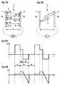
- the EDM machining devices known generally include an electrode 1 serving as a tool and a workpiece machine 2 at least partially contained in a fluid or machining liquid 3.
- a voltage source 4 makes it possible to apply for example through a resistance a voltage between electrode 1 and part 2 after closing a switch 5.
- Figures 2A and 2B show in correspondence with Figure 1 and known way the tension (figure 2A) and the current (figure 2B) in the space of working width L between the electrode and the part.
- Figure 1 shows, according to the state of the art and in correspondence with FIGS. 2A and 2B, the average displacement P1 of the ions, having a charge electric negative 6 and having a positive electric charge 7, during the time waiting time to, in the space of width L containing the dielectric fluid 3 separating the electrode 1 and the part 2.
- the voltage source 4 applies a voltage such that electrode 1 has a negative electrical charge 8 and the part 2 has a positive electric charge 9. It follows that the ions having a positive electrical charge 7 will bombard electrode 1 and the ions having a negative electrical charge 6 will bomb room 2 and cause the phenomenon of electrolysis which damages its surface.
- FIGS. 3A and 3B in correspondence with FIGS. 4A and 4B refer to other devices known from the state of the art and which aim to reduce the harmful effects of electrolysis. These devices include at least two voltage sources 4 and 10 of opposite polarities.
- the voltage source 4 does not apply voltage to the electrode 1 and the part 2.
- the voltage source 10 applies to the electrode 1 and to the part 2 a voltage of opposite polarity to that applied to them by the voltage source 4 during the time ta during which the main discharge of erosive current takes place.
- a control unit allowing the switching from the voltage source 10 to the voltage source 4 is not reproduced in the drawing to make it more clear.
- the voltage between the electrode 1 and the part 2 is of opposite polarity to that applied during the discharge, as indicated in FIG. 4A, while only a small ion current flows between the electrode 1 and the part 2, as shown in fig. 4B.
- a conductive channel is formed in the dielectric fluid 3 and a current is established between the electrode 1 and the part 2, as shown in fig.4B.
- a device for detecting this current not shown because it is well known in the state of the art, detects the sudden increase in current between the electrode 1 and the part 2, and the control unit, also well known in the art.
- the voltage source 10 triggers the voltage source 10 and activates the voltage source 4 to generate the main discharge of erosive current.
- the voltage between the electrode 1 and the part 2 is of opposite polarity to that applied during the main discharge, as shown in FIGS. 4A and 4B.
- a time t A or sparking time begins.
- This time t A is subdivided into a time t R or delay or preparation time and a time t C or discharge time proper.
- the main voltage source 4 is switched on.
- There is however a switch-on delay of a duration determined by the electronic and electrical circuits of the source 4 corresponding to this delay time t R until the voltage (FIG. 4A) and the current (FIG. 4B ) are reversed.
- the delay time t R ends and the discharge time t C begins, during which the discharge takes place.
- FIG. 3A shows, according to the state of the art and in correspondence with FIGS. 4A and 4B, the displacement P1 of the ions, having a negative electric charge 6 and having a positive electric charge 7, during the time duration t D , in the space of width L containing the dielectric fluid 3 separating the electrode 1 and the part 2.
- the voltage source 10 applies a voltage such that the electrode 1 has a positive electric charge and the part 2 has a negative electrical charge. It follows that the ions having a negative electric charge 6 will no longer bombard the part 2, as in the case of FIG.
- FIG. 3B shows, according to the state of the art and in correspondence with FIGS. 4A and 4B, the space of width L containing the dielectric fluid 3 separating the electrode 1 and the part 2, during the time t C during from which the main erosive current discharge takes place 14.
- the voltage source 10 is triggered and the voltage source 4 is switched on, thereby generating the main erosive current discharge 14.
- an alternating voltage is applied between the electrode and the workpiece by means of an alternating voltage source.
- the frequency of this voltage is fixed at a value such that the ions present in the fluid carry out weak oscillating return journeys, in any case substantially shorter than the machining distance L separating the electrode from the part.
- the frequency can typically be chosen between 0.1 and 10 MHz.
- no ion current flows in the working space or gap G between the electrode 1 and the part 2.
- ion current we mean a current due to displacements of the ions going from l electrode to the piece or vice versa.
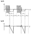
- the voltage between the electrode and the part changes polarity with a frequency which is constant in Figure 5A. Note during this phase a small galvanic current generally less than 0.5 A due to the distributed capacities of the workpiece and tool electrodes which charge and discharge, as shown in Figure 5B.
- a conductive channel forms in the dielectric fluid or liquid 3 and a current begins to be established between l electrode and the workpiece, while the starting voltage U decreases considerably.
- a suitable detection device detects a sudden increase in current and activates a DC voltage source to generate and maintain the main discharge of erosive current during the next phase, called the sparking phase t A.
- the latter is in fact subdivided into two distinct periods, a first period t R during which only a small current of the order of 2 to 6 A flows between the electrode and the part and whose polarity still depends on the polarity of the AC voltage from the AC voltage source.
- This first period corresponds to a delay time t R or of preparation belonging to the duration of activation of the main discharge, time during which the current of the main discharge arises.
- the duration of this delay time t R depends on the electrical and electronic circuits of the DC voltage generator and is substantially constant for each erosive discharge during machining. Its duration is typically from 0.2 to 0.8 ⁇ sec.
- the second period t C of the sparking phase t A corresponds to a current time during which the erosive discharge takes place and is maintained by the DC voltage source.
- the duration of this sparking phase t A is fixed so as to obtain optimum efficiency and quality of machining.
- the duration of the sparking phase may typically be 2 ⁇ sec, it being understood that the person skilled in the art will fix its value according to predetermined experimental data.
- the end of this phase and the start of the next pause phase t B is obtained by cutting off the DC and AC voltage sources.
- no voltage is applied between the electrode and the workpiece so that the machining fluid or liquid present between the electrode and the workpiece is deionized and the ionized channel disappears entirely.
- the conductivity of the gap decreases very quickly.
- phase cycle of each discharge begins with a time or a pause phase t B during which this deionization takes place.
- This pause phase is absolutely necessary because it prevents two discharges or a series of discharges from successively bursting in the same place and causing a break in the wire by an excessive supply of heat there. Its duration will favorably be between 1 and 20 ⁇ sec.
- each discharge is preceded by a random time, called phase or waiting time t D during which a new ionized channel is created and the conductivity of the gap increases gradually and more and more quickly.
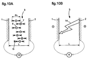
- the ions due to the high frequency alternating voltage, oscillate around a position of equilibrium; the distance over which the oscillation takes place is very less than the width of the space between the electrode and the part. So, none ion bombardment is not possible.
- both the ions having a positive electrical charge 7 and the ions having a negative electrical charge 6 oscillate around an equilibrium position with an average distance traveled P2 less than the width L of the space. separating the electrode 1 from the part. Thus, both the ions having a positive electrical charge 7 and the ions having a negative electrical charge 6 will no longer bombard either the part 2 or the electrode 1. The electrolysis phenomenon is thus completely eliminated.
- the electrical / electronic circuits connecting these sources 12 and 4 to the electrode and the part are not illustrated, but may include for the alternating voltage source 12 a current limiter and for the source of direct voltage of the switching transistors.
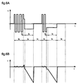
- the frequency of the alternating voltage source 12 is not constant, but this frequency is variable and gradually decreases with time t.
- a frequency spectrum of the alternating voltage is therefore scanned to find the frequency most suitable for forming an ionized channel and a current through the gap G.
- This frequency spectrum could also be modulated so as to increase and decrease successively.
- sparking t A , delay t R , discharge t C and pause t B phases remain unchanged. This variant is particularly well suited to machining conditions with difficult priming.
- the frequency of the alternating voltage source 12 is modulated in pulse width according to a so-called PWM method ( pulse width modulation).
- PWM method pulse width modulation
- FIGS. 8A and 8B A third variant of the machining process is shown in FIGS. 8A and 8B illustrating the voltage and the current between the electrode and the part during the different phases of the process.
- the alternating voltage is stopped and the voltage is blocked, from the start of the delay phase t R , on the positive or negative polarity.
- this polarity could be random and correspond to that present during the appearance and detection of the current between the electrode and the part.
- This polarity could also be predetermined and always correspond to the same polarity.
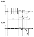
- FIGS. 9A and 9B show the voltage and the current through the gap as a function of time.
- an alternating voltage is also applied between the electrode and the part during the waiting time t D and the sparking time t A.
- both the amplitude and the duration of the positive pulses are different from the negative pulses.
- These positive and negative pulses can also be modulated according to a determined duty cycle.
- the positive pulses of voltage U have a different amplitude, for example greater, than that of the negative pulses, while no current I flows through the gap, except a weak current due the electrolytic conductivity of the machining liquid.
- a conductive channel is formed in the dielectric fluid and a sudden discharge current is established between the electrode tool and the part, as shown in FIG. 9B.
- a device for detecting this discharge current detects the passage of current between the electrode 1 and the part 2, and another device activates the DC voltage source to generate the main discharge of erosive current which is established after a phase of delay t R.
- the high frequency alternating voltage can be fixed in such a way that the average voltage during a discharge is either zero, positive or negative.
- the value of the voltage U decreases as soon as the current I appears at the start of the sparking phase t A and of delay t R.
- the voltage U and the current I take the polarity of the DC voltage source 4 and a strong increase in the current I is observed during the discharge phase t C , while the amplitude of the voltage U remains substantially the same as that during the previous delay phase t R.
- the values for the voltage U between the electrode and the workpiece during the different phases can typically be ⁇ 50 to ⁇ 200 V during the standby phase t D , from 20 to 30 V during the sparking phase t A and 0 V during the pause phase.
- the current I flowing between the electrode and the part can typically have values of 2 to 6 A during the delay phase t R and peak currents from 500 A to 800 A during the discharge phase t C. During the latter, the currents have a triangular shape because of the significant line choke.
- the growth phase of the current is of the order of a microsecond.
- the DC voltage source 4 is arranged so as to be able to provide a instantaneous power of around 1 to 1.5 KW and a voltage of up to 300V when empty, that is to say when it does not charge.
- a waiting phase t D there will therefore be a waiting phase t D , a delay phase t R , a discharge phase t C and a pause phase t B.
- an additional delay period t ' R will be inserted between the waiting phase t D and the delay phase t R.
- the duration of the delay time t R of the main voltage source is fixed so that at least one complete period and one complete cycle of the alternating voltage is obtained for each discharge. at least one positive and one negative pulse before the main source voltage is applied.
- the duration t D of the priming waiting time can become very short.
- the alternating voltage is then applied for a very short time before the main discharge for a succession of discharges, so that all the discharges are initiated only on a single polarity, for example positive.
- electrolysis can occur during this succession of rapid primings.
- the alternating voltage always presents a positive and negative alternation, there is no unilateral ion migration.
- the waiting time t D is random, we can then act on the delay time t R which depends on the main voltage source by fixing t R so that t R ⁇ T - t D where T is the period of the alternating voltage of the alternating voltage source. If the duration to of the waiting phase is very short, the duration of the delay time t R equal to or greater than a period T of the alternating voltage can be fixed.
- FIG 11. An embodiment of a device for implementing the methods shown in Figures 5 to 8 is illustrated in Figure 11.
- This device includes an electrical / electronic circuit with two main branches 30, 31 each connected between electrode 1 and workpiece 2.
- a first branch 30 serves as an alternating voltage generator 12 and the second branch 31 DC generator 4.
- the entire circuit is controlled by a control unit 32.
- the first branch 30 comprises a voltage source 34 capable of supply a voltage for example between 50 and 200 V for a power of the order of 300 W.
- the positive terminal of this voltage source 34 is connected to the electrode 1 by a diode 36 and a switch 40 and to the piece 2 by a diode 38 and a switch 42.
- the negative terminal of this source 34 is connected to electrode 1 by a switch 43 and a diode 39 and to the workpiece by a switch 41 and a diode 37.
- the opening and closing of switches 40 to 43, formed favorably by field effect transistors, are controlled and controlled by the unit 32.
- the first branch 30 further comprises a limiter current 44 which could be integrated into the voltage source 34.
- a sensor for current 50 makes it possible to measure the current I between the electrode 1 and the part 2 and to transmit the result of the measurements to the control unit 32.
- the latter is arranged to close transistors 40 and 41 to apply a voltage of positive polarity between the electrode 1 and the part 2, the transistors 42 and 43 being open, and then to close the transistors 42 and 43 to apply a voltage of negative polarity between electrode 1 and the part, the transistors 40 and 41 being open.
- the second branch 31 comprises a DC voltage source 45 with a voltage of 200 to 300 V at no load, that is to say when it does not flow, and with an instantaneous power of approximately 1 to 1.5 kW.
- the positive terminal of this source is connected to the part 2 by a switch 46 and its negative terminal is connected to the electrode 1 by a switch 47.
- This branch 31 further comprises a diode 48 connecting the junction between the output of the switch 47 and the electrode 1 at the input of the switch 46 and a diode 49 connecting the input of the switch 47 to the junction between the output of the switch 46 and the part 2.
- the switches 46 and 47 are preferably transistors whose opening and closing are controlled by the control unit 32.
- the DC voltage generator 4 is switched on after the detection of a current by the sensor 50, marking the end of the waiting phase t D.
- the control unit 32 controls the closing of the switches 46, 47 for this purpose. This closing can be ordered immediately after detection of the current or after a predetermined delay time period t ' R.
- the control unit 32 controls the opening of the switches 46, 47 to trigger the DC voltage generator 4 and also the opening of all the switches 40 to 43 of the first branch 30, if these switches have not already been opened before.
- the erosive discharge is then cut and one enters the pause phase t B during which no voltage is applied between the electrode and the part until a complete deionization of the gap is obtained.
- the next cycle can then start with the waiting phase to by applying the alternating voltage controlled by the control unit 32 according to the methods described with reference to FIGS. 5 to 8.
- FIG. 12 A variant of the device described above is illustrated in FIG. 12 and comprises a second branch 31 with a similar DC voltage generator 4. Similar items therefore have the same reference numbers.
- the first branch 30 comprising the alternating voltage generator 12 is of another type and comprises two voltage sources 55, 56 of reverse polarity and whose voltages are adjustable.
- a first source 55 is connected between the electrode 1 and the part 2 by connecting its negative terminal to the electrode 1 by means of a switch 58, a current limiter 59 and a diode 60.
- the second source 56 is also connected in parallel between electrode 1 and part 2 by connecting its positive terminal to electrode 1 via a switch 61 and a current limiter 62.
- the control unit 32 can thus alternately open and close the switches 58 and 61 to activate the voltage sources 55 or 56 whose voltages are preferably different. It is therefore possible to obtain, with this alternative embodiment, an alternating voltage as illustrated in FIG. 9A and comprising positive and negative voltage alternations of different amplitude and duration. The succession of the different phases t D , t A , t B during each discharge remains however the same.
- the values for the sources 55, 56 and 45 voltages may typically be 80, 100 and 300 V.
- the electronic circuits for generating the alternating and direct voltages may be of any other nature.
- the current diagrams I as a function of time may have very different increases and decreases in current during the current phase t c .
- the alternating voltage source can be cut at any time after the main discharge has started, namely at the start of the current time t c , and until the end of the latter.
- the device may include any means for adjusting and fixing the delay time t r when the main discharge is switched on.
Landscapes
- Engineering & Computer Science (AREA)
- Mechanical Engineering (AREA)
- Chemical & Material Sciences (AREA)
- Chemical Kinetics & Catalysis (AREA)
- Electrochemistry (AREA)
- Electrical Discharge Machining, Electrochemical Machining, And Combined Machining (AREA)
Applications Claiming Priority (2)
| Application Number | Priority Date | Filing Date | Title |
|---|---|---|---|
| CH202699 | 1999-11-05 | ||
| CH02026/99A CH693529A5 (fr) | 1999-11-05 | 1999-11-05 | Procede et dispositif d'usinage par electroerosion. |
Publications (2)
| Publication Number | Publication Date |
|---|---|
| EP1097773A1 true EP1097773A1 (de) | 2001-05-09 |
| EP1097773B1 EP1097773B1 (de) | 2003-01-29 |
Family
ID=4224195
Family Applications (1)
| Application Number | Title | Priority Date | Filing Date |
|---|---|---|---|
| EP00122962A Expired - Lifetime EP1097773B1 (de) | 1999-11-05 | 2000-10-23 | Verfahren und Vorrichtung zur Funkenerosionsbearbeitung |
Country Status (7)
| Country | Link |
|---|---|
| US (1) | US6465754B1 (de) |
| EP (1) | EP1097773B1 (de) |
| JP (1) | JP2001162444A (de) |
| KR (1) | KR100721779B1 (de) |
| CH (1) | CH693529A5 (de) |
| DE (1) | DE60001299T2 (de) |
| ES (1) | ES2190392T3 (de) |
Cited By (2)
| Publication number | Priority date | Publication date | Assignee | Title |
|---|---|---|---|---|
| EP1604766A3 (de) * | 2004-06-10 | 2005-12-21 | Charmilles Technologies S.A. | Stützteil für die untere Drahtführung einer Funkenerosionsmaschine |
| EP1886755A1 (de) * | 2006-08-11 | 2008-02-13 | Charmilles Technologies S.A. | Vorrichtung und Verfahren für Hochfrequenz Funkenerosionsbearbeitung |
Families Citing this family (6)
| Publication number | Priority date | Publication date | Assignee | Title |
|---|---|---|---|---|
| DE10084876B4 (de) * | 2000-06-06 | 2006-06-08 | Mitsubishi Denki K.K. | Funkenerosions-Stromversorgungssystem |
| KR101235485B1 (ko) | 2005-12-27 | 2013-02-20 | 두산인프라코어 주식회사 | 와이어컷 방전 가공장치의 교류전원장치 |
| DE112008003658B4 (de) * | 2008-01-31 | 2015-12-10 | Mitsubishi Electric Corp. | Elektrische Entladungsbearbeitungsvorrichtung |
| JP4874358B2 (ja) * | 2009-02-27 | 2012-02-15 | 株式会社ソディック | 形彫放電加工装置の加工用電源装置 |
| CN105033371B (zh) * | 2015-08-12 | 2017-10-03 | 清华大学 | 一种电加工用防电化学杂散腐蚀的方法 |
| US12409504B2 (en) * | 2019-02-05 | 2025-09-09 | Huys Industries Limited | Welding applicator and method of application |
Citations (5)
| Publication number | Priority date | Publication date | Assignee | Title |
|---|---|---|---|---|
| US4447696A (en) * | 1974-02-19 | 1984-05-08 | Mitsubishi Denki Kabushiki Kaisha | Process and apparatus for high frequency discharge shaping of a workpiece by means of a rectangular bipolar pulsating voltage |
| JPS63260721A (ja) * | 1987-04-16 | 1988-10-27 | Inoue Japax Res Inc | 放電加工方法 |
| JPH03294116A (ja) * | 1990-04-10 | 1991-12-25 | Makino Milling Mach Co Ltd | 放電加工パルスの供給方法及び装置 |
| EP0545156A2 (de) * | 1991-12-02 | 1993-06-09 | Mitsubishi Denki Kabushiki Kaisha | Funkenerosionsmaschine |
| US5698115A (en) * | 1993-06-30 | 1997-12-16 | Mitsubishi Denki Kabushiki Kaisha | Electrical discharge machine |
Family Cites Families (7)
| Publication number | Priority date | Publication date | Assignee | Title |
|---|---|---|---|---|
| JPS50119394A (de) * | 1974-03-06 | 1975-09-18 | ||
| JPS59232726A (ja) * | 1983-06-13 | 1984-12-27 | Mitsubishi Electric Corp | 放電加工装置用加工電源 |
| CH678825A5 (de) * | 1986-06-03 | 1991-11-15 | Mitsubishi Electric Corp | |
| JPH081438A (ja) * | 1994-06-27 | 1996-01-09 | Fanuc Ltd | 放電加工方法及びその装置 |
| DE4432916C1 (de) * | 1994-09-15 | 1996-04-04 | Agie Ag Ind Elektronik | Verfahren und Impulsgenerator zum elektroerosiven Bearbeiten von Werkstücken |
| JP3294116B2 (ja) | 1995-09-28 | 2002-06-24 | 株式会社東芝 | 半導体集積回路 |
| JP3645957B2 (ja) * | 1995-12-28 | 2005-05-11 | 株式会社ソディック | 放電加工方法及び装置 |
-
1999
- 1999-11-05 CH CH02026/99A patent/CH693529A5/fr not_active IP Right Cessation
-
2000
- 2000-10-23 ES ES00122962T patent/ES2190392T3/es not_active Expired - Lifetime
- 2000-10-23 DE DE60001299T patent/DE60001299T2/de not_active Expired - Lifetime
- 2000-10-23 EP EP00122962A patent/EP1097773B1/de not_active Expired - Lifetime
- 2000-11-02 JP JP2000335829A patent/JP2001162444A/ja active Pending
- 2000-11-04 KR KR1020000065341A patent/KR100721779B1/ko not_active Expired - Fee Related
- 2000-11-06 US US09/705,881 patent/US6465754B1/en not_active Expired - Lifetime
Patent Citations (5)
| Publication number | Priority date | Publication date | Assignee | Title |
|---|---|---|---|---|
| US4447696A (en) * | 1974-02-19 | 1984-05-08 | Mitsubishi Denki Kabushiki Kaisha | Process and apparatus for high frequency discharge shaping of a workpiece by means of a rectangular bipolar pulsating voltage |
| JPS63260721A (ja) * | 1987-04-16 | 1988-10-27 | Inoue Japax Res Inc | 放電加工方法 |
| JPH03294116A (ja) * | 1990-04-10 | 1991-12-25 | Makino Milling Mach Co Ltd | 放電加工パルスの供給方法及び装置 |
| EP0545156A2 (de) * | 1991-12-02 | 1993-06-09 | Mitsubishi Denki Kabushiki Kaisha | Funkenerosionsmaschine |
| US5698115A (en) * | 1993-06-30 | 1997-12-16 | Mitsubishi Denki Kabushiki Kaisha | Electrical discharge machine |
Non-Patent Citations (2)
| Title |
|---|
| PATENT ABSTRACTS OF JAPAN vol. 013, no. 055 (M - 795) 8 February 1989 (1989-02-08) * |
| PATENT ABSTRACTS OF JAPAN vol. 016, no. 132 (M - 1229) 3 April 1992 (1992-04-03) * |
Cited By (4)
| Publication number | Priority date | Publication date | Assignee | Title |
|---|---|---|---|---|
| EP1604766A3 (de) * | 2004-06-10 | 2005-12-21 | Charmilles Technologies S.A. | Stützteil für die untere Drahtführung einer Funkenerosionsmaschine |
| EP1886755A1 (de) * | 2006-08-11 | 2008-02-13 | Charmilles Technologies S.A. | Vorrichtung und Verfahren für Hochfrequenz Funkenerosionsbearbeitung |
| CN101121211B (zh) * | 2006-08-11 | 2011-01-12 | 夏米尔技术股份公司 | 用于高频放电加工的设备和方法 |
| US8093527B2 (en) | 2006-08-11 | 2012-01-10 | Charmilles Technologies Sa | Device and method for high frequency electrical discharge machining |
Also Published As
| Publication number | Publication date |
|---|---|
| ES2190392T3 (es) | 2003-08-01 |
| DE60001299T2 (de) | 2003-11-06 |
| KR20010051444A (ko) | 2001-06-25 |
| CH693529A5 (fr) | 2003-09-30 |
| US6465754B1 (en) | 2002-10-15 |
| EP1097773B1 (de) | 2003-01-29 |
| DE60001299D1 (de) | 2003-03-06 |
| JP2001162444A (ja) | 2001-06-19 |
| KR100721779B1 (ko) | 2007-05-25 |
Similar Documents
| Publication | Publication Date | Title |
|---|---|---|
| EP1097773B1 (de) | Verfahren und Vorrichtung zur Funkenerosionsbearbeitung | |
| CH655032A5 (fr) | Machine a decharge electrique pour electro-erosion. | |
| FR2649252A1 (fr) | Procede et dispositif de decharge d'un arc electrique dans un liquide electriquement conducteur et application au lithotrypteur | |
| FR2473929A1 (fr) | Procede et dispositif d'usinage par decharges electriques | |
| CH684828A5 (fr) | Générateur d'impulsions pour usiner par électro-érosion. | |
| CH689256A5 (fr) | Ensemble d'alimentation électrique pour traitement par décharges dans une machine d'électroérosion. | |
| EP0187770B1 (de) | Elektrische schaltung für funkerosionsbearbeitungsvorrichtung | |
| EP1063043B1 (de) | Verfahren und Vorrichtung zur Funkenerosionsbearbeitung | |
| EP2896127B1 (de) | Generator für viereckige hochleistungspulse mit einstellbarer flankrensteilheit | |
| FR2716040A1 (fr) | Commande de diode laser pulsée, compacte, à fréquence de répétition d'impulsion élévée et de grande puissance. | |
| EP1493522B1 (de) | Funkenerosionsmaschine | |
| FR2488175A1 (fr) | Procede et appareil d'usinage par decharges electriques | |
| CH644290A5 (en) | Pulse generator for electrical discharge machining | |
| CH651770A5 (fr) | Dispositif d'usinage par electroerosion. | |
| WO2004103626A1 (fr) | Dispositif d’usinage par electroerosion | |
| CH649024A5 (fr) | Machine pour usiner par decharges electriques erosives. | |
| FR2462229A1 (fr) | Procede et appareil d'usinage par decharges electriques | |
| Malik et al. | The normal current density effect in barrier discharge | |
| EP0572717B1 (de) | Impulsgenerator zur elektroerosiven Bearbeitung | |
| CH477128A (fr) | Circuit générateur d'impulsions | |
| BE514778A (de) | ||
| FR2476143A1 (fr) | Procede de traitement thermochimique de pieces par bombardement ionique et dispositif pour la mise en oeuvre du procede | |
| WO2001005033A2 (fr) | Dispositif et procede pour generer des variations controlees intenses et breves de pression magnetique au sein d'un echantillon de materiau solide | |
| FR3086565A1 (fr) | Procede de traitement d’une piece poreuse | |
| BE893034A (fr) | Appareil a laser |
Legal Events
| Date | Code | Title | Description |
|---|---|---|---|
| PUAI | Public reference made under article 153(3) epc to a published international application that has entered the european phase |
Free format text: ORIGINAL CODE: 0009012 |
|
| AK | Designated contracting states |
Kind code of ref document: A1 Designated state(s): DE ES FR GB IT |
|
| AX | Request for extension of the european patent |
Free format text: AL;LT;LV;MK;RO;SI |
|
| 17P | Request for examination filed |
Effective date: 20010806 |
|
| AKX | Designation fees paid |
Free format text: DE ES FR GB IT |
|
| GRAH | Despatch of communication of intention to grant a patent |
Free format text: ORIGINAL CODE: EPIDOS IGRA |
|
| GRAH | Despatch of communication of intention to grant a patent |
Free format text: ORIGINAL CODE: EPIDOS IGRA |
|
| GRAA | (expected) grant |
Free format text: ORIGINAL CODE: 0009210 |
|
| AK | Designated contracting states |
Designated state(s): DE ES FR GB IT |
|
| REG | Reference to a national code |
Ref country code: GB Ref legal event code: FG4D Free format text: NOT ENGLISH |
|
| REF | Corresponds to: |
Ref document number: 60001299 Country of ref document: DE Date of ref document: 20030306 Kind code of ref document: P |
|
| GBT | Gb: translation of ep patent filed (gb section 77(6)(a)/1977) |
Effective date: 20030401 |
|
| REG | Reference to a national code |
Ref country code: ES Ref legal event code: FG2A Ref document number: 2190392 Country of ref document: ES Kind code of ref document: T3 |
|
| PLBE | No opposition filed within time limit |
Free format text: ORIGINAL CODE: 0009261 |
|
| STAA | Information on the status of an ep patent application or granted ep patent |
Free format text: STATUS: NO OPPOSITION FILED WITHIN TIME LIMIT |
|
| 26N | No opposition filed |
Effective date: 20031030 |
|
| REG | Reference to a national code |
Ref country code: FR Ref legal event code: PLFP Year of fee payment: 16 |
|
| REG | Reference to a national code |
Ref country code: FR Ref legal event code: PLFP Year of fee payment: 17 |
|
| REG | Reference to a national code |
Ref country code: FR Ref legal event code: PLFP Year of fee payment: 18 |
|
| PGFP | Annual fee paid to national office [announced via postgrant information from national office to epo] |
Ref country code: ES Payment date: 20171121 Year of fee payment: 18 |
|
| REG | Reference to a national code |
Ref country code: FR Ref legal event code: PLFP Year of fee payment: 19 |
|
| PGFP | Annual fee paid to national office [announced via postgrant information from national office to epo] |
Ref country code: DE Payment date: 20181019 Year of fee payment: 19 |
|
| PGFP | Annual fee paid to national office [announced via postgrant information from national office to epo] |
Ref country code: GB Payment date: 20181019 Year of fee payment: 19 Ref country code: IT Payment date: 20181024 Year of fee payment: 19 Ref country code: FR Payment date: 20181022 Year of fee payment: 19 |
|
| REG | Reference to a national code |
Ref country code: ES Ref legal event code: FD2A Effective date: 20191203 |
|
| PG25 | Lapsed in a contracting state [announced via postgrant information from national office to epo] |
Ref country code: ES Free format text: LAPSE BECAUSE OF NON-PAYMENT OF DUE FEES Effective date: 20181024 |
|
| REG | Reference to a national code |
Ref country code: DE Ref legal event code: R119 Ref document number: 60001299 Country of ref document: DE |
|
| PG25 | Lapsed in a contracting state [announced via postgrant information from national office to epo] |
Ref country code: DE Free format text: LAPSE BECAUSE OF NON-PAYMENT OF DUE FEES Effective date: 20200501 |
|
| GBPC | Gb: european patent ceased through non-payment of renewal fee |
Effective date: 20191023 |
|
| PG25 | Lapsed in a contracting state [announced via postgrant information from national office to epo] |
Ref country code: GB Free format text: LAPSE BECAUSE OF NON-PAYMENT OF DUE FEES Effective date: 20191023 Ref country code: FR Free format text: LAPSE BECAUSE OF NON-PAYMENT OF DUE FEES Effective date: 20191031 Ref country code: IT Free format text: LAPSE BECAUSE OF NON-PAYMENT OF DUE FEES Effective date: 20191023 |