EP1098032B1 - Dispositif d' étanchéité pour agencement d' égouttage de pâte à papier - Google Patents
Dispositif d' étanchéité pour agencement d' égouttage de pâte à papier Download PDFInfo
- Publication number
- EP1098032B1 EP1098032B1 EP00202594A EP00202594A EP1098032B1 EP 1098032 B1 EP1098032 B1 EP 1098032B1 EP 00202594 A EP00202594 A EP 00202594A EP 00202594 A EP00202594 A EP 00202594A EP 1098032 B1 EP1098032 B1 EP 1098032B1
- Authority
- EP
- European Patent Office
- Prior art keywords
- seal
- screen member
- nip
- distance
- arrangement
- Prior art date
- Legal status (The legal status is an assumption and is not a legal conclusion. Google has not performed a legal analysis and makes no representation as to the accuracy of the status listed.)
- Expired - Lifetime
Links
- 238000007789 sealing Methods 0.000 title claims abstract description 42
- 239000000835 fiber Substances 0.000 claims abstract description 15
- 238000005406 washing Methods 0.000 claims abstract description 4
- 239000000725 suspension Substances 0.000 claims abstract description 3
- 239000007788 liquid Substances 0.000 claims description 8
- 229920001131 Pulp (paper) Polymers 0.000 description 6
- 238000004140 cleaning Methods 0.000 description 2
- 238000011144 upstream manufacturing Methods 0.000 description 2
- 229920002678 cellulose Polymers 0.000 description 1
- 239000001913 cellulose Substances 0.000 description 1
- 238000010276 construction Methods 0.000 description 1
- 239000012535 impurity Substances 0.000 description 1
- 238000004519 manufacturing process Methods 0.000 description 1
- 239000000463 material Substances 0.000 description 1
- 238000005259 measurement Methods 0.000 description 1
- 238000000034 method Methods 0.000 description 1
- 230000000149 penetrating effect Effects 0.000 description 1
- 238000003825 pressing Methods 0.000 description 1
- 239000000126 substance Substances 0.000 description 1
- 230000007704 transition Effects 0.000 description 1
Images


Classifications
-
- D—TEXTILES; PAPER
- D21—PAPER-MAKING; PRODUCTION OF CELLULOSE
- D21D—TREATMENT OF THE MATERIALS BEFORE PASSING TO THE PAPER-MAKING MACHINE
- D21D1/00—Methods of beating or refining; Beaters of the Hollander type
- D21D1/20—Methods of refining
- D21D1/40—Washing the fibres
-
- D—TEXTILES; PAPER
- D21—PAPER-MAKING; PRODUCTION OF CELLULOSE
- D21C—PRODUCTION OF CELLULOSE BY REMOVING NON-CELLULOSE SUBSTANCES FROM CELLULOSE-CONTAINING MATERIALS; REGENERATION OF PULPING LIQUORS; APPARATUS THEREFOR
- D21C9/00—After-treatment of cellulose pulp, e.g. of wood pulp, or cotton linters ; Treatment of dilute or dewatered pulp or process improvement taking place after obtaining the raw cellulosic material and not provided for elsewhere
- D21C9/18—De-watering; Elimination of cooking or pulp-treating liquors from the pulp
-
- D—TEXTILES; PAPER
- D21—PAPER-MAKING; PRODUCTION OF CELLULOSE
- D21F—PAPER-MAKING MACHINES; METHODS OF PRODUCING PAPER THEREON
- D21F1/00—Wet end of machines for making continuous webs of paper
- D21F1/66—Pulp catching, de-watering, or recovering; Re-use of pulp-water
- D21F1/74—Pulp catching, de-watering, or recovering; Re-use of pulp-water using cylinders
- D21F1/76—Pulp catching, de-watering, or recovering; Re-use of pulp-water using cylinders with suction
Definitions
- the present invention relates to a sealing arrangement according to the pre-characterizing clause of Claim 1.
- a previously known and commonly used arrangement for washing and dewatering paper pulp, called a wash press, is disclosed in SE-C-380,300, SE-C-501, 710, US 5,488,900 and SE-C-504, 011.
- the arrangements disclosed in these documents comprise two cylindrical, rotatable screen members arranged in an essentially converging vat.
- Other examples of known arrangements are disclosed in US 4,543,161 and in US 5, 667, 642, the latter constituting an arrangement in which the screen members rotate in the opposite direction to the conventional one, that is to say, as seen from the short end, the right-hand screen member rotates counter-clockwise and the left one rotates clockwise.
- a second variant shown in Figures 5 - 7, is a variant with low-friction shields which bear against the end walls of the drum in the area of the nip and prevent the pulp from being pressed out to the sides in the nip.
- This type of seal becomes greatly worn because the very high local hydraulic and mechanical pressures against the ends of the drum in the smallest cross section of the nip are maintained.
- An object of the present invention is to permit an improved sealing of the end walls of the wash press by means of controlled pressure relief at the end walls of the screen drum.
- a further object is to make available a wash press with improved sealing of the end walls, which sealing allows fibre residues, which may be pressed into the pressure relief zone, to be continuously returned to the level of the envelope surface downstream of the nip. In this way, it is possible to avoid successive build-up of an increasingly hard dewatered fibre plug.
- the wash press can in this way be operated for longer periods of time without unnecessary shutdown for cleaning, or without the need for complicated cleaning arrangements.
- Yet another object is to make available a wash press with improved sealing of the end walls, which sealing consists of a sealing profile, preferably with a pressurized seal, which affords a cost-effective sealing construction.
- Yet another object of a preferred embodiment with pressurized sealing is that the pressure can be kept at a constant level in the whole sealing strip, while at the same time achieving an optimum sealing capacity around the entire circumference of the end wall.
- the pressure relief in the area of the nip means that one and the same pressure can be applied in the seal and still be sufficient in the area of the nip where the press forces on the pulp web are extremely high.
- a contiguous sealing element can be used with just one pressurizing chamber. The seal does not therefore need to be divided into parts, pressurized at different levels, and this reduces the costs of the seal and of the pressurizing system for the sealing strip.
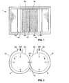
- FIG. 1 and 2 The type of wash press in which the sealing arrangement according to the invention is used is shown in Figures 1 and 2 and comprises two hollow, circular-cylindrical screen members 2a, 2b which include a number of evacuation chambers (not shown) under the envelope surface of the screen member for the purpose of leading off evacuated liquid.
- the pulp suspension WP is fed into the inlet boxes 3a and 3b and transported, under rotation of the screen members 2a, 2b, into a converging gap between a vat 6 and the surface of the screen members 2a, 2b, and onwards to a nip 10 between the screen members.
- the dewatered pulp DP is then withdrawn upwards after it has passed the nip 10.
- the two screen members form a press nip 10 between each other and are arranged to rotate towards each other, so that, as seen from the short end ( Figure 2), the right-hand screen member rotates clockwise and the left-hand screen member rotates counter-clockwise.
- the wash press 1 preferably has a diameter of 1.0 - 2.5 metres. Its envelope 3 is also perforated in order to allow liquid to be evacuated from a web of fibre pulp lying against the envelope surface.
- a pulp inlet box 3a, 3b is arranged on each drum 2a, 2b, respectively.
- Each pulp inlet box 3a, 3b is arranged at 0° on the wash press, where 0° represents the highest/uppermost point of the wash press and the degrees increase positively in the direction of rotation of the screen member.
- Incoming paper pulp which normally has a concentration of about 1 - 12%, preferably 3 - 10%, is distributed uniformly across the length of the screen member by means of the inlet box.
- the screen members are arranged to rotate at a speed of 5 - 20 rpm by means of a suitable drive device. Paper pulp thus follows the rotation of the screen members in the gap between the perforated envelope surface 2a, 2b and the walls of the vat 6, where it forms a web of fibre pulp which is dewatered by virtue of the fact that the gap converges in the direction towards the nip.
- the liquid which is pressed out from the web of fibre pulp is led off (not shown) from the arrangement.
- wash liquid can be introduced into the web of fibre pulp, and the latter is washed.
- the web of fibre pulp is dewatered, by means of the pressure in the nip 10, to a concentration which is about 5 - 20 times higher than the concentration of the incoming paper pulp, for example 1 - 12% on admission and 25 - 40% downstream of the nip.
- the web of fibre pulp is torn off from the envelope 2a, 2b and led off from the arrangement by means of suitable shredders/conveyor screws.
- a sealing arrangement comprises a seal 8 which seals between the end wall 5a, 5b of the screen member and a housing 13 surrounding the screen member, in the area of the end wall 5a, 5b.
- the seal 8 is arranged at a first distance from the circumferential plane of a screen member along at least a predetermined part of the periphery of the screen member, but excluding the area at the nip 10, and the sealing element is arranged at a second distance X from the circumferential plane of the screen member near the nip 10, the second distance being greater than the first distance.
- the distance X from the plane of the envelope surface in the area of the nip corresponds to a measurement in the range of 10 - 1000 millimetres, preferably 20 - 60 millimetres, more preferably 25 millimetres.
- the first distance at which the seal is arranged from the plane of the envelope surface corresponds essentially to a 0 distance, meaning that the sealing arrangement touches the plane of the envelope surface. In this way, it is possible to achieve complete sealing against those areas of the pulp web where the pressures are not as high as in the press nip 10. This prevents fibre becoming packed in the gap between the end wall of the drum and the seal holder. The gap is necessary for manufacturing tolerances and heat expansion.
- the sealing arrangement is retracted towards the centre of rotation of the screen member, in the area of the nip, across an angle range in the range of 15 - 60 degrees, preferably 25 - 50 degrees, more preferably 25 - 35 degrees.
- the seal thus lies in such a way that it touches the plane of the envelope surface over the remaining parts of the turn.
- the first distance for the seal, resulting in the seal touching the plane of the envelope surface is formed over an angle in the range of 300 - 345 degrees, preferably 310 - 335 degrees, more preferably 325 - 335 degrees.
- the seal To achieve a good transition between the retracted position of the seal and the position in which it touches the plane of the envelope surface, it is advantageous for the seal to converge seamlessly to the first distance in the angle range by which the seal is retracted relative to the envelope surface of the screen member. This provides a symmetrical retraction of the seal 8 around the press nip 10, i.e. identical upstream and downstream of the press nip 10.
- the preferred seal is a pressurized seal corresponding to that shown in Figures 4 and 5.
- the seal comprises a pressurizing chamber arranged in the housing 13, which pressurizing chamber acts on the sealing surfaces 8 of the seal against the end walls 5a, 5b of the drum.
- Exchangeable wear rings 14 are preferably arranged on the end walls.
- the seal also preferably consists of a sealing element 8 which is contiguous in the circumferential direction, with identical sealing profile, which sealing element is arranged in a groove in a seal holder 9 arranged on the housing 13.
- the seal 8 can in turn be provided with sealing rings 12 which prevent impurities from penetrating into the pressure chamber and, if appropriate, permit pressurizing directly in the groove for the seal 8.
- the pressurizing chamber 11 of the seal preferably consists of a pressurizing chamber 11 which is contiguous in the circumferential direction, which pressurizing chamber 11 is arranged in the bottom of the groove in the seal holder 9.
- pressurizing chamber 11 may preferably be made integral with the sealing part of the seal 8 in the same way as with "CEFILAIR®" pneumatic seals.
- the seal can be retracted asymmetrically around the press nip 10. It can be retracted starting immediately in front of the press nip and it can more quickly reach the maximum retracted distance, which distance is maintained for a length after the press nip.
- the so-called "0 distance" between the seal and the plane of the envelope surface, excluding the area around the press nip 10, can of course be given a minimum drawing-in corresponding to a fraction of the drawing-in at the press nip 10.
- the essential feature of the inventive concept is that pressure relief in the press nip is permitted by the fact that the pressure can be temporarily led off across the end surface of the drum.
- a local drain or pressure outlet can be arranged upstream or downstream of the press nip, radially outwards from the retracted seal.
- An extra drain in the holder 9 can facilitate evacuation of liquid which is pressed out at the press nip.
- An outlet for compressed air directly downstream of the press nip can prevent the build-up of fibre plugs.
- wash zones where liquid is also added to remove the liquid in the fibre web, can be introduced between the inlet boxes and the press nip 10.
- the wash zones can also be completely omitted, in which case only pressing of the pulp web is carried out.
Landscapes
- Life Sciences & Earth Sciences (AREA)
- Engineering & Computer Science (AREA)
- Wood Science & Technology (AREA)
- Paper (AREA)
Claims (10)
- Agencement (1) de lavage et d'égouttage d'une suspension de pâte de fibre, ledit agencement comprenant deux éléments de tamis circulaires cylindriques (2a, 2b) présentant chacun une surface d'enveloppe et des parois d'extrémité, lesdits éléments de tamis circulaires cylindriques étant arrangés de manière à tourner l'un vers l'autre afin de former un point de contact (10), au moins un desdits éléments de tamis étant creux afin de permettre une évacuation de liquide radialement vers l'intérieur de l'élément de tamis, au moins l'élément de tamis creux (2a, 2b) étant arrangé dans une cuve (6) qui renferme partiellement l'enveloppe de l'élément de tamis, ladite cuve, dans le sens de rotation de l'élément de tamis, convergeant en direction de l'enveloppe de l'élément de tamis, et dans lequel au moins un boítier d'entrée de pâte (3a, 3b) est arrangé à proximité de l'élément de tamis afin d'introduire de la pâte entre l'enveloppe de l'élément de tamis (2a, 2b) et sa cuve (6) en vue de former une bande de pâte de fibre sur l'élément de tamis, dans lequel l'agencement comprend un dispositif d'étanchéité comportant un joint (8) qui assure une isolation entre la paroi d'extrémité (5a, 5b) de l'élément de tamis et une enceinte (13) qui entoure l'élément de tamis dans la région de la paroi d'extrémité, dans lequel le joint (8) est arrangé à une première distance du plan circonférentiel de l'enveloppe de l'élément de tamis le long d'au moins une partie prédéterminée de la périphérie de l'élément de tamis, mais excluant la région voisine du point de contact (10), et dans lequel l'élément d'étanchéité est arrangé à une deuxième distance (X) du plan circonférentiel de l'enveloppe de l'élément de tamis dans la région du point de contact (10), caractérisé en ce que le joint est rétracté par rapport au plan circonférentiel de l'enveloppe de l'élément de tamis en direction du centre de rotation de l'élément de tamis, dans la région du point de contact, de telle sorte que la deuxième distance (X) soit plus grande que la première distance.
- Agencement suivant la revendication 1, caractérisé en ce que le dispositif d'étanchéité est arrangé à la distance X par rapport au plan de la surface de l'enveloppe dans la région du point de contact, et en ce que la distance X correspond à une mesure comprise entre 10 et 1000 millimètres, de préférence entre 20 et 60 millimètres, et plus préférablement égale à 25 millimètres.
- Agencement suivant la revendication 1 ou 2, caractérisé en ce que la première distance à laquelle le dispositif d'étanchéité est arrangé par rapport au plan de la surface de l'enveloppe correspond essentiellement à une distance 0, ce qui signifie que le dispositif d'étanchéité touche le plan de la surface de l'enveloppe.
- Agencement suivant l'une quelconque des revendications précédentes, caractérisé en ce que le dispositif d'étanchéité est rétracté en direction du centre de rotation de l'élément de tamis, dans la région du point de contact, à travers un angle compris entre 15 et 60 degrés, de préférence entre 25 et 50 degrés, et plus préférablement entre 25 et 35 degrés.
- Agencement suivant la revendication 4, caractérisé en ce que la première distance du joint, qui signifie que le joint touche le plan de la surface de l'enveloppe, est formée sur un angle compris entre 300 et 345 degrés, de préférence entre 310 et 335 degrés, et plus préférablement entre 325 et 335 degrés.
- Agencement suivant la revendication 4, caractérisé en ce que le joint (8) est rétracté en direction du centre de rotation de l'élément de tamis, dans la région du point de contact, à la distance X, et en ce que le joint change d'une façon continue jusqu'à la première distance dans la plage angulaire dans laquelle le joint est rétracté par rapport à la surface de l'enveloppe de l'élément de tamis.
- Agencement suivant l'une quelconque des revendications précédentes, caractérisé en ce que le joint comprend une chambre de pressurisation (11) arrangée dans l'enceinte (13), ladite chambre de pressurisation agissant sur les surfaces d'étanchéité (8) du joint contre les parois d'extrémité (5a, 5b) du tambour, lesdites parois d'extrémité comprenant de préférence des anneaux d'usure échangeables (14).
- Agencement suivant la revendication 7, caractérisé en ce que le joint est constitué d'un élément d'étanchéité (8) qui est contigu dans la direction circonférentielle, ledit élément d'étanchéité étant arrangé dans une rainure dans un porte-joint (9) disposé sur l'enceinte (13).
- Agencement suivant la revendication 8, caractérisé en ce que la chambre de pressurisation (11) du joint est constituée d'une chambre de pressurisation (11) qui est contiguë dans la direction circonférentielle, ladite chambre de pressurisation (11) étant arrangée dans une rainure dans un porte-joint (9) disposé sur l'enceinte (13).
- Agencement suivant la revendication 9, caractérisé en ce que la chambre de pressurisation (11) est intégrée avec la partie d'étanchéité du joint (8).
Applications Claiming Priority (2)
| Application Number | Priority Date | Filing Date | Title |
|---|---|---|---|
| SE9903078 | 1999-08-27 | ||
| SE9903078A SE9903078L (sv) | 1999-08-27 | 1999-08-27 | Tätningsanordning för tvättpress |
Publications (3)
| Publication Number | Publication Date |
|---|---|
| EP1098032A2 EP1098032A2 (fr) | 2001-05-09 |
| EP1098032A3 EP1098032A3 (fr) | 2002-04-10 |
| EP1098032B1 true EP1098032B1 (fr) | 2004-01-28 |
Family
ID=20416813
Family Applications (1)
| Application Number | Title | Priority Date | Filing Date |
|---|---|---|---|
| EP00202594A Expired - Lifetime EP1098032B1 (fr) | 1999-08-27 | 2000-07-19 | Dispositif d' étanchéité pour agencement d' égouttage de pâte à papier |
Country Status (6)
| Country | Link |
|---|---|
| US (1) | US6402894B1 (fr) |
| EP (1) | EP1098032B1 (fr) |
| AT (1) | ATE258615T1 (fr) |
| CA (1) | CA2314702C (fr) |
| DE (1) | DE60007940T2 (fr) |
| SE (1) | SE9903078L (fr) |
Families Citing this family (5)
| Publication number | Priority date | Publication date | Assignee | Title |
|---|---|---|---|---|
| FI20001603L (fi) * | 2000-07-04 | 2002-01-05 | Andritz Ahlstrom Oy | Tiivistejõrjestely |
| SE517932C2 (sv) * | 2001-09-19 | 2002-08-06 | Kvaerner Pulping Tech | Tätningsordning för trumfilter eller filterpressar samt manschett och hållarelement till en sådan |
| SE528728C2 (sv) * | 2005-06-03 | 2007-02-06 | Metso Paper Inc | Anordning för behandling av cellulosamassa |
| SE1651480A1 (sv) * | 2016-11-11 | 2018-05-02 | Valmet Oy | A pressure device for a sealing arrangement, a sealing arrangement and an apparatus for processing pulp |
| US12303812B2 (en) | 2019-10-31 | 2025-05-20 | Bhs-Sonthofen Gmbh | Rotary pressure filter |
Family Cites Families (3)
| Publication number | Priority date | Publication date | Assignee | Title |
|---|---|---|---|---|
| US2396694A (en) * | 1941-05-31 | 1946-03-19 | Beloit Iron Works | Cylinder type papermaking machine and method |
| SE380300C (sv) * | 1974-03-04 | 1984-10-29 | Sunds Ab | Anordning for vetskebehandling av en fibersuspension |
| DE3463342D1 (en) * | 1983-08-09 | 1987-06-04 | Fujimoto Pollcon Co | Double cylinder press for formation of fibrous layers |
-
1999
- 1999-08-27 SE SE9903078A patent/SE9903078L/ not_active IP Right Cessation
-
2000
- 2000-07-19 DE DE60007940T patent/DE60007940T2/de not_active Expired - Lifetime
- 2000-07-19 EP EP00202594A patent/EP1098032B1/fr not_active Expired - Lifetime
- 2000-07-19 AT AT00202594T patent/ATE258615T1/de active
- 2000-07-27 CA CA002314702A patent/CA2314702C/fr not_active Expired - Fee Related
- 2000-08-09 US US09/635,979 patent/US6402894B1/en not_active Expired - Fee Related
Also Published As
| Publication number | Publication date |
|---|---|
| EP1098032A3 (fr) | 2002-04-10 |
| SE9903078D0 (sv) | 1999-08-27 |
| ATE258615T1 (de) | 2004-02-15 |
| SE513154C2 (sv) | 2000-07-17 |
| CA2314702A1 (fr) | 2001-02-27 |
| DE60007940T2 (de) | 2004-11-04 |
| EP1098032A2 (fr) | 2001-05-09 |
| SE9903078L (sv) | 2000-07-17 |
| US6402894B1 (en) | 2002-06-11 |
| CA2314702C (fr) | 2009-10-06 |
| DE60007940D1 (de) | 2004-03-04 |
Similar Documents
| Publication | Publication Date | Title |
|---|---|---|
| US4359827A (en) | High speed paper drying | |
| US4286512A (en) | Screw-press | |
| CA1178804A (fr) | Secheur a vide pour procede de fabrication du papier a haute vitesse | |
| US3642139A (en) | Apparatus for centrifugally removing liquid from a mixture | |
| KR100457172B1 (ko) | 제지기계의흡인로울용시일구조 | |
| US4016032A (en) | Suction roll for transferring a web away from a press section | |
| US5667642A (en) | Pulp slurry-handling press roll and twin and single roll slurry handling presses | |
| CA2314702C (fr) | Dispositif d'etancheite pour essoreuse de pate | |
| EP1244839B1 (fr) | Systeme d'etancheite pour unite de deshydratation de pate a papier | |
| US20100050461A1 (en) | Paper machine | |
| WO1994008088A1 (fr) | Nouveau procede pour enlever l'eau du bain de lessive contenue dans des particules solides | |
| US8048273B2 (en) | Arrangement for treatment of cellulose pulp | |
| US8556087B2 (en) | Arrangement for the treatment of cellulose pulp in a washing apparatus arranged with a reinforcing frame | |
| EP2694726A1 (fr) | Dispositif d'étanchéité pour un scellement étanche entre un premier tambour et un élément de boîtier d'extrémité | |
| EP3590696B1 (fr) | Agencement d'une presse à rouleau, appareil de rouleau de presse et procédé de déshydratation de charge granulaire fibreuse | |
| US3477907A (en) | Press arrangement for papermaking machine | |
| CA2736197C (fr) | Dispositif d'etancheite et appareil pour traiter la pate de cellulose | |
| NZ256481A (en) | Removing liquor from pulp by application of first and second pressure differentials with the latter being in excess of 60 kpa | |
| WO2019066710A1 (fr) | Appareil de lavage et/ou d'essorage de pâte à papier |
Legal Events
| Date | Code | Title | Description |
|---|---|---|---|
| PUAI | Public reference made under article 153(3) epc to a published international application that has entered the european phase |
Free format text: ORIGINAL CODE: 0009012 |
|
| AK | Designated contracting states |
Kind code of ref document: A2 Designated state(s): AT BE CH CY DE DK ES FI FR GB GR IE IT LI LU MC NL PT SE |
|
| AX | Request for extension of the european patent |
Free format text: AL;LT;LV;MK;RO;SI |
|
| PUAL | Search report despatched |
Free format text: ORIGINAL CODE: 0009013 |
|
| AK | Designated contracting states |
Kind code of ref document: A3 Designated state(s): AT BE CH CY DE DK ES FI FR GB GR IE IT LI LU MC NL PT SE |
|
| AX | Request for extension of the european patent |
Free format text: AL;LT;LV;MK;RO;SI |
|
| 17P | Request for examination filed |
Effective date: 20020722 |
|
| AKX | Designation fees paid |
Free format text: AT BE CH CY DE DK ES FI FR GB GR IE IT LI LU MC NL PT SE |
|
| 17Q | First examination report despatched |
Effective date: 20030403 |
|
| GRAP | Despatch of communication of intention to grant a patent |
Free format text: ORIGINAL CODE: EPIDOSNIGR1 |
|
| GRAS | Grant fee paid |
Free format text: ORIGINAL CODE: EPIDOSNIGR3 |
|
| GRAA | (expected) grant |
Free format text: ORIGINAL CODE: 0009210 |
|
| AK | Designated contracting states |
Kind code of ref document: B1 Designated state(s): AT BE CH CY DE DK ES FI FR GB GR IE IT LI LU MC NL PT SE |
|
| PG25 | Lapsed in a contracting state [announced via postgrant information from national office to epo] |
Ref country code: IT Free format text: LAPSE BECAUSE OF FAILURE TO SUBMIT A TRANSLATION OF THE DESCRIPTION OR TO PAY THE FEE WITHIN THE PRESCRIBED TIME-LIMIT;WARNING: LAPSES OF ITALIAN PATENTS WITH EFFECTIVE DATE BEFORE 2007 MAY HAVE OCCURRED AT ANY TIME BEFORE 2007. THE CORRECT EFFECTIVE DATE MAY BE DIFFERENT FROM THE ONE RECORDED. Effective date: 20040128 Ref country code: BE Free format text: LAPSE BECAUSE OF FAILURE TO SUBMIT A TRANSLATION OF THE DESCRIPTION OR TO PAY THE FEE WITHIN THE PRESCRIBED TIME-LIMIT Effective date: 20040128 Ref country code: CH Free format text: LAPSE BECAUSE OF FAILURE TO SUBMIT A TRANSLATION OF THE DESCRIPTION OR TO PAY THE FEE WITHIN THE PRESCRIBED TIME-LIMIT Effective date: 20040128 Ref country code: NL Free format text: LAPSE BECAUSE OF FAILURE TO SUBMIT A TRANSLATION OF THE DESCRIPTION OR TO PAY THE FEE WITHIN THE PRESCRIBED TIME-LIMIT Effective date: 20040128 Ref country code: LI Free format text: LAPSE BECAUSE OF FAILURE TO SUBMIT A TRANSLATION OF THE DESCRIPTION OR TO PAY THE FEE WITHIN THE PRESCRIBED TIME-LIMIT Effective date: 20040128 Ref country code: FR Free format text: LAPSE BECAUSE OF FAILURE TO SUBMIT A TRANSLATION OF THE DESCRIPTION OR TO PAY THE FEE WITHIN THE PRESCRIBED TIME-LIMIT Effective date: 20040128 Ref country code: CY Free format text: LAPSE BECAUSE OF FAILURE TO SUBMIT A TRANSLATION OF THE DESCRIPTION OR TO PAY THE FEE WITHIN THE PRESCRIBED TIME-LIMIT Effective date: 20040128 |
|
| REG | Reference to a national code |
Ref country code: GB Ref legal event code: FG4D |
|
| REG | Reference to a national code |
Ref country code: CH Ref legal event code: EP |
|
| REG | Reference to a national code |
Ref country code: IE Ref legal event code: FG4D |
|
| REF | Corresponds to: |
Ref document number: 60007940 Country of ref document: DE Date of ref document: 20040304 Kind code of ref document: P |
|
| PG25 | Lapsed in a contracting state [announced via postgrant information from national office to epo] |
Ref country code: DK Free format text: LAPSE BECAUSE OF FAILURE TO SUBMIT A TRANSLATION OF THE DESCRIPTION OR TO PAY THE FEE WITHIN THE PRESCRIBED TIME-LIMIT Effective date: 20040428 Ref country code: GR Free format text: LAPSE BECAUSE OF FAILURE TO SUBMIT A TRANSLATION OF THE DESCRIPTION OR TO PAY THE FEE WITHIN THE PRESCRIBED TIME-LIMIT Effective date: 20040428 Ref country code: SE Free format text: LAPSE BECAUSE OF FAILURE TO SUBMIT A TRANSLATION OF THE DESCRIPTION OR TO PAY THE FEE WITHIN THE PRESCRIBED TIME-LIMIT Effective date: 20040428 |
|
| PG25 | Lapsed in a contracting state [announced via postgrant information from national office to epo] |
Ref country code: ES Free format text: LAPSE BECAUSE OF FAILURE TO SUBMIT A TRANSLATION OF THE DESCRIPTION OR TO PAY THE FEE WITHIN THE PRESCRIBED TIME-LIMIT Effective date: 20040509 |
|
| NLV1 | Nl: lapsed or annulled due to failure to fulfill the requirements of art. 29p and 29m of the patents act | ||
| PG25 | Lapsed in a contracting state [announced via postgrant information from national office to epo] |
Ref country code: LU Free format text: LAPSE BECAUSE OF NON-PAYMENT OF DUE FEES Effective date: 20040719 Ref country code: IE Free format text: LAPSE BECAUSE OF NON-PAYMENT OF DUE FEES Effective date: 20040719 Ref country code: GB Free format text: LAPSE BECAUSE OF NON-PAYMENT OF DUE FEES Effective date: 20040719 |
|
| PG25 | Lapsed in a contracting state [announced via postgrant information from national office to epo] |
Ref country code: MC Free format text: LAPSE BECAUSE OF NON-PAYMENT OF DUE FEES Effective date: 20040731 |
|
| REG | Reference to a national code |
Ref country code: CH Ref legal event code: PL |
|
| PLBE | No opposition filed within time limit |
Free format text: ORIGINAL CODE: 0009261 |
|
| STAA | Information on the status of an ep patent application or granted ep patent |
Free format text: STATUS: NO OPPOSITION FILED WITHIN TIME LIMIT |
|
| 26N | No opposition filed |
Effective date: 20041029 |
|
| EN | Fr: translation not filed | ||
| GBPC | Gb: european patent ceased through non-payment of renewal fee |
Effective date: 20040719 |
|
| REG | Reference to a national code |
Ref country code: IE Ref legal event code: MM4A |
|
| PG25 | Lapsed in a contracting state [announced via postgrant information from national office to epo] |
Ref country code: PT Free format text: LAPSE BECAUSE OF NON-PAYMENT OF DUE FEES Effective date: 20040628 |
|
| PGFP | Annual fee paid to national office [announced via postgrant information from national office to epo] |
Ref country code: FI Payment date: 20120727 Year of fee payment: 13 |
|
| PGFP | Annual fee paid to national office [announced via postgrant information from national office to epo] |
Ref country code: DE Payment date: 20120727 Year of fee payment: 13 |
|
| PGFP | Annual fee paid to national office [announced via postgrant information from national office to epo] |
Ref country code: AT Payment date: 20120719 Year of fee payment: 13 |
|
| REG | Reference to a national code |
Ref country code: AT Ref legal event code: MM01 Ref document number: 258615 Country of ref document: AT Kind code of ref document: T Effective date: 20130719 |
|
| PG25 | Lapsed in a contracting state [announced via postgrant information from national office to epo] |
Ref country code: DE Free format text: LAPSE BECAUSE OF NON-PAYMENT OF DUE FEES Effective date: 20140201 Ref country code: FI Free format text: LAPSE BECAUSE OF NON-PAYMENT OF DUE FEES Effective date: 20130719 |
|
| REG | Reference to a national code |
Ref country code: DE Ref legal event code: R119 Ref document number: 60007940 Country of ref document: DE Effective date: 20140201 |
|
| PG25 | Lapsed in a contracting state [announced via postgrant information from national office to epo] |
Ref country code: AT Free format text: LAPSE BECAUSE OF NON-PAYMENT OF DUE FEES Effective date: 20130719 |