EP1098037A2 - Schienentrenneinrichtung - Google Patents
Schienentrenneinrichtung Download PDFInfo
- Publication number
- EP1098037A2 EP1098037A2 EP00120516A EP00120516A EP1098037A2 EP 1098037 A2 EP1098037 A2 EP 1098037A2 EP 00120516 A EP00120516 A EP 00120516A EP 00120516 A EP00120516 A EP 00120516A EP 1098037 A2 EP1098037 A2 EP 1098037A2
- Authority
- EP
- European Patent Office
- Prior art keywords
- rail
- guide frame
- axis
- machine
- cut
- Prior art date
- Legal status (The legal status is an assumption and is not a legal conclusion. Google has not performed a legal analysis and makes no representation as to the accuracy of the status listed.)
- Granted
Links
- 238000006073 displacement reaction Methods 0.000 claims description 3
- 238000000926 separation method Methods 0.000 description 4
- 208000027418 Wounds and injury Diseases 0.000 description 1
- 238000006243 chemical reaction Methods 0.000 description 1
- 238000002485 combustion reaction Methods 0.000 description 1
- 230000006378 damage Effects 0.000 description 1
- 230000002349 favourable effect Effects 0.000 description 1
- 208000014674 injury Diseases 0.000 description 1
- 238000009420 retrofitting Methods 0.000 description 1
Images

Classifications
-
- E—FIXED CONSTRUCTIONS
- E01—CONSTRUCTION OF ROADS, RAILWAYS, OR BRIDGES
- E01B—PERMANENT WAY; PERMANENT-WAY TOOLS; MACHINES FOR MAKING RAILWAYS OF ALL KINDS
- E01B31/00—Working rails, sleepers, baseplates, or the like, in or on the line; Machines, tools, or auxiliary devices specially designed therefor
- E01B31/02—Working rail or other metal track components on the spot
- E01B31/04—Sectioning or slitting, e.g. by sawing, shearing, flame-cutting
-
- B—PERFORMING OPERATIONS; TRANSPORTING
- B23—MACHINE TOOLS; METAL-WORKING NOT OTHERWISE PROVIDED FOR
- B23D—PLANING; SLOTTING; SHEARING; BROACHING; SAWING; FILING; SCRAPING; LIKE OPERATIONS FOR WORKING METAL BY REMOVING MATERIAL, NOT OTHERWISE PROVIDED FOR
- B23D45/00—Sawing machines or sawing devices with circular saw blades or with friction saw discs
- B23D45/006—Sawing machines or sawing devices with circular saw blades or with friction saw discs with means to attach the sawing device to the workpiece
Definitions
- the invention relates to a rail separating device for dividing a rail, with one - a drive motor and one that can be rotated by it
- Cutting wheel having - cutting machine that on attached to a guide frame and normal to the longitudinal direction of the rail is designed to be movable, and with a clamping device which can be fixed on the rail, on which the guide frame by one in the longitudinal direction of the rail extending pivot axis is articulated.
- Such rail separation devices are already in a variety of designs and became known from many literature examples.
- the device is placed on the rail head and using the clamping device fixed on it, after which the cut-off machine by means of the guide frame moved relative to the rail and this is cut.
- the guide frame can, e.g. in US 5,486,136 as normal to the rail Slide rod be formed on which the cutting machine sliding as well as tiltable.
- the management framework itself is more common, e.g. in US 4,033,074, on the clamping device about an axis parallel to the rail tilted.
- the guide frame often also consists of two hinges interconnected arms, e.g.
- AT 334 242 proposed the cutting machine on the guide frame by means of a Attach the spindle so that the machine alternates into two 180 ° rotated positions can be fixed manually to the frame while this remains unchanged mounted on the rail and only from one is turned over to the other side. This allows the rail cut from both sides with somewhat reduced conversion work become.
- the object of the present invention is now to create a Rail separation device of the type mentioned, with one more better and easier use of the cutting disc under the ergonomic favorable conditions is possible.
- Such training now allows, in a highly advantageous manner, cutting a rail from both sides without the machine to disassemble or dismantle in the slightest.
- This can the cutting disc even with advanced wear still used without any problems and without restricting work performance while any given by any retrofitting work Risk of injury can be reliably avoided.
- Turning around The entire cut-off machine can be extremely simple and ergonomic advantageous way by simply swiveling - without loosening the clamping device - do not affect the operator in any way Wise.
- the training according to the invention also has the advantage that the flying sparks at the grinding point always point downwards, no matter which side is cut.
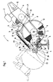
- the rail separation device 1 shown in FIGS. 1 and 2 essentially consists from a cut-off machine 2, which has a guide frame 3 connected to a clamping device 4 and for splitting a rail 5 is provided.
- the cut-off machine 2 has an axis 6 rotatably mounted cutting wheel 7, which in a known manner a drive chain or a drive belt 8 by means of a drive motor 9 is rotatable.
- the engine in the present case is a gasoline engine educated; the use of other types of engines is however also possible without restriction.
- the cut-off machine 2 is also with a rotatable about the axis 6 and in their respective position lockable spark protection hood 10 and with handles 11 and controls 12 equipped.
- the cut-off machine 2 is at one end 13 of the guide frame 3 attached, with its other end 14 on the - as a screw clamp 15 trained and fixable on the rail 5 - clamping device 4 stored is.
- the guide frame 3 consists of two hinged together connected arms 17 pivotable relative to one another about an axis 16 and 18, which are biased towards each other by means of a spring 19.
- the attachment the cut-off machine 2 on the guide frame 3 takes place via a Spindle 20, which rotates machine 2 relative to guide frame 3 allowed and can be fixed by means of a quick release device 21.
- the leadership framework 3 allows the cutting wheel 7 to move normally to the longitudinal direction of the rail 5, being in the operating position of the machine 2 axes 6 and 16 and spindle 20 parallel to the longitudinal direction of the rails run.
- a rotating device 22 is provided, by means of which the guide frame 3 together with the cut-off machine suspended from it 2 rotatable about a vertical axis of rotation 23 relative to the clamping device 4 is.
- the rotating device 22 consists essentially of a support plate 24, which rests on a horizontal surface 25 of the screw clamp 15 and has a bore 26.
- a vertical, on the clamp 15 attached clamping screw 27 with a Nut 28.
- the clamping screw 27 thus forms the vertical axis of rotation 23 around which the support plate 24 or the rotating device 22 by at least Can be rotated 180 ° and locked in its respective position by means of the nut 28 is.
- a horizontal slide rod 29 is arranged on the support plate 24 which the end 14 of the guide frame 3 is displaceable by means of a sliding bush 30 is stored.
- the slide rod 29 runs parallel to the axes 6 and 16 and forms a pivot axis 31 around which the guide frame 3 together the cut-off machine 2 can be tilted in the vertical plane while the guide frame 3 simultaneously in the direction of the pivot axis 31 the slide rod 29 is displaceable relative to the clamping device 4.
- the displacement route a corresponds to the sliding bush 30 on the slide rod 29 at least twice the horizontal measured in the longitudinal direction of the rail Distance b of the cutting wheel 7 from the vertical axis of rotation 23 (see Fig. 2).
- the rail separating device 1 is placed on the rail 5 and on the basis of the screw clamp 15 of the clamping device 4 fixed. Then the rail 5 is cut - as in FIGS. 1 and 2 shown in full lines - from one side of the rail.
- the leadership framework 3 is expediently on the slide rod 29 up to the stop shifted to the left (seen by the operator) and can be held in this position so easily. Is the cut-off wheel 7 still relatively new, the rail 5 can entirely from this one side be severed here. With advanced wear of the grinding wheel and the resulting smaller diameter does not succeed more.
Landscapes
- Engineering & Computer Science (AREA)
- Mechanical Engineering (AREA)
- Architecture (AREA)
- Civil Engineering (AREA)
- Structural Engineering (AREA)
- Finish Polishing, Edge Sharpening, And Grinding By Specific Grinding Devices (AREA)
- Processing Of Stones Or Stones Resemblance Materials (AREA)
- Branching, Merging, And Special Transfer Between Conveyors (AREA)
- Escalators And Moving Walkways (AREA)
- Seal Device For Vehicle (AREA)
- Sawing (AREA)
Abstract
Description
Claims (6)
- Schienentrenneinrichtung (1) zum Teilen einer Schiene (5), mit einer - einen Antriebsmotor (9) und eine von diesem in Rotation versetzbare Trennschleifscheibe (7) aufweisenden - Trennschleifmaschine (2), die auf einem Führungsrahmen (3) befestigt und normal zur Längsrichtung der Schiene (5) bewegbar ausgebildet ist, und mit einer auf der Schiene (5) fixierbaren Klemmvorrichtung (4), an der der Führungsrahmen (3) um eine in Schienenlängsrichtung verlaufende Schwenkachse (31) kippbar angelenkt ist, dadurch gekennzeichnet, daß der Führungsrahmen (3) anhand einer Drehvorrichtung (22) um eine vertikale Drehachse (23) verdrehbar mit der Klemmvorrichtung (4) verbunden ist, und daß die Trennschleifmaschine (2) in Richtung der Schwenkachse (31) relativ zur Klemmvorrichtung (4) verschiebbar ausgebildet ist.
- Schienentrenneinrichtung nach Anspruch 1, dadurch gekennzeichnet, daß die Drehvorrichtung (22) zur Verdrehung des Führungsrahmens (3) über die Drehachse (23) um 180° ausgebildet ist.
- Schienentrenneinrichtung nach Anspruch 1 oder 2, dadurch gekennzeichnet, daß die Drehvorrichtung (22) im wesentlichen aus einer mit dem Führungsrahmen (3) verbundenen Stützplatte (24) besteht, die auf einer horizontalen Oberfläche (25) einer die Klemmvorrichtung (4) bildenden Schraubzwinge (15) drehbar gelagert und auf dieser anhand einer Spannschraube (27) arretierbar ist.
- Schienentrenneinrichtung nach einem der Ansprüche 1 bis 3, dadurch gekennzeichnet, daß die Drehachse (23) durch die Spannschraube (27) gebildet ist.
- Schienentrenneinrichtung nach Anspruch 3 oder 4, dadurch gekennzeichnet, daß die Stützplatte (24) eine die Schwenkachse (31) bildende, horizontale Gleitstange (29) aufweist, auf der ein der Trennschleifmaschine (2) gegenüberliegendes Ende (14) des Führungsrahmens (3) mittels einer Gleitbuchse (30) verschiebbar gelagert ist.
- Schienentrenneinrichtung nach Anspruch 5, dadurch gekennzeichnet, daß die Länge der Gleitstange (29) bzw. der Verschiebeweg (a) der Gleitbuchse (30) mindestens dem doppelten, in Schienenlängsrichtung gemessenen Abstand (b) der Trennschleifscheibe (7) von der Drehachse (23) entspricht.
Applications Claiming Priority (2)
| Application Number | Priority Date | Filing Date | Title |
|---|---|---|---|
| DE29919225U | 1999-11-02 | ||
| DE29919225U DE29919225U1 (de) | 1999-11-02 | 1999-11-02 | Schienentrenneinrichtung |
Publications (3)
| Publication Number | Publication Date |
|---|---|
| EP1098037A2 true EP1098037A2 (de) | 2001-05-09 |
| EP1098037A3 EP1098037A3 (de) | 2001-07-04 |
| EP1098037B1 EP1098037B1 (de) | 2005-01-12 |
Family
ID=8081059
Family Applications (1)
| Application Number | Title | Priority Date | Filing Date |
|---|---|---|---|
| EP00120516A Expired - Lifetime EP1098037B1 (de) | 1999-11-02 | 2000-09-20 | Schienentrenneinrichtung |
Country Status (3)
| Country | Link |
|---|---|
| EP (1) | EP1098037B1 (de) |
| AT (1) | ATE287009T1 (de) |
| DE (2) | DE29919225U1 (de) |
Cited By (4)
| Publication number | Priority date | Publication date | Assignee | Title |
|---|---|---|---|---|
| WO2005113896A1 (en) | 2004-05-12 | 2005-12-01 | The Stanley Works | Portable rail cutting apparatus |
| EP1619306A1 (de) * | 2004-07-22 | 2006-01-25 | Thermit Italiana S.r.l. | Halterung für Schienensägen |
| RU2405880C2 (ru) * | 2005-10-05 | 2010-12-10 | Робел Банбаумашинен Гмбх | Зажимное устройство для фиксации станка для обработки пути |
| DE102019200303A1 (de) * | 2019-01-11 | 2020-07-16 | Robel Bahnbaumaschinen Gmbh | Trennschleifgerät und Verfahren zum Durchtrennen einer Schiene eines Gleises |
Citations (4)
| Publication number | Priority date | Publication date | Assignee | Title |
|---|---|---|---|---|
| AT334242B (de) | 1974-04-09 | 1976-01-10 | Geismar Ancien Ets L | Trennschleifmaschine |
| US4033074A (en) | 1975-10-28 | 1977-07-05 | Safetran Systems Corporation | Portable rail saw |
| FR2704791A1 (fr) | 1993-05-03 | 1994-11-10 | Electrolux Ab | Appareil formant une machine à découper ou une scie circulaire. |
| US5486136A (en) | 1992-06-15 | 1996-01-23 | Kabushiki Kaisha Yamazaki Haguruma Seisakusho | Cutting machine for railroad rail |
Family Cites Families (3)
| Publication number | Priority date | Publication date | Assignee | Title |
|---|---|---|---|---|
| US2214141A (en) * | 1937-10-27 | 1940-09-10 | Mall Arthur William | Rail slotter |
| US5842637A (en) * | 1995-07-13 | 1998-12-01 | Midwest Rail Inc. | Angled joint for railroad rails |
| JP3910673B2 (ja) * | 1996-12-25 | 2007-04-25 | 太平工業株式会社 | ワーク切断機における切断位置切換え装置 |
-
1999
- 1999-11-02 DE DE29919225U patent/DE29919225U1/de not_active Expired - Lifetime
-
2000
- 2000-09-20 AT AT00120516T patent/ATE287009T1/de active
- 2000-09-20 DE DE50009205T patent/DE50009205D1/de not_active Expired - Lifetime
- 2000-09-20 EP EP00120516A patent/EP1098037B1/de not_active Expired - Lifetime
Patent Citations (4)
| Publication number | Priority date | Publication date | Assignee | Title |
|---|---|---|---|---|
| AT334242B (de) | 1974-04-09 | 1976-01-10 | Geismar Ancien Ets L | Trennschleifmaschine |
| US4033074A (en) | 1975-10-28 | 1977-07-05 | Safetran Systems Corporation | Portable rail saw |
| US5486136A (en) | 1992-06-15 | 1996-01-23 | Kabushiki Kaisha Yamazaki Haguruma Seisakusho | Cutting machine for railroad rail |
| FR2704791A1 (fr) | 1993-05-03 | 1994-11-10 | Electrolux Ab | Appareil formant une machine à découper ou une scie circulaire. |
Cited By (9)
| Publication number | Priority date | Publication date | Assignee | Title |
|---|---|---|---|---|
| WO2005113896A1 (en) | 2004-05-12 | 2005-12-01 | The Stanley Works | Portable rail cutting apparatus |
| US7059947B2 (en) | 2004-05-12 | 2006-06-13 | The Stanley Works | Portable rail cutting apparatus |
| US7131897B2 (en) | 2004-05-12 | 2006-11-07 | The Stanley Works | Portable rail cutting apparatus |
| EP1795650A3 (de) * | 2004-05-12 | 2007-07-04 | The Stanley Works | Tragbare Schienenschneidvorrichtung |
| EP1619306A1 (de) * | 2004-07-22 | 2006-01-25 | Thermit Italiana S.r.l. | Halterung für Schienensägen |
| RU2405880C2 (ru) * | 2005-10-05 | 2010-12-10 | Робел Банбаумашинен Гмбх | Зажимное устройство для фиксации станка для обработки пути |
| DE102019200303A1 (de) * | 2019-01-11 | 2020-07-16 | Robel Bahnbaumaschinen Gmbh | Trennschleifgerät und Verfahren zum Durchtrennen einer Schiene eines Gleises |
| EP3740618B1 (de) | 2019-01-11 | 2021-03-03 | Robel Bahnbaumaschinen GmbH | Trennschleifgerät und verfahren zum durchtrennen einer schiene eines gleises |
| US12059736B2 (en) | 2019-01-11 | 2024-08-13 | Robel Bahnbaumaschinen Gmbh | Cutting grinder and method for cutting through a rail of a track |
Also Published As
| Publication number | Publication date |
|---|---|
| DE29919225U1 (de) | 2000-12-14 |
| DE50009205D1 (de) | 2005-02-17 |
| EP1098037A3 (de) | 2001-07-04 |
| EP1098037B1 (de) | 2005-01-12 |
| ATE287009T1 (de) | 2005-01-15 |
Similar Documents
| Publication | Publication Date | Title |
|---|---|---|
| DE69102087T2 (de) | Schnittiefeneinstellvorrichtung für tragbare Kreissägen. | |
| DE2405992C2 (de) | Sägemaschine | |
| DE602004008336T2 (de) | Vorrichtung zum schärfen von kettensägezähnen | |
| EP2366482B1 (de) | Mehrachsiger Vorritzer | |
| EP3740618B1 (de) | Trennschleifgerät und verfahren zum durchtrennen einer schiene eines gleises | |
| DE2915288A1 (de) | Kaltkreissaege | |
| EP0445406B1 (de) | Vorrichtung zum horizontalen Spannen des auf einem Maschinentisch einer Vertikalsäge aufliegenden Werkstückmaterials | |
| DE1552887A1 (de) | Bearbeitungsvorrichtung | |
| DE2750166A1 (de) | Therapeutisches geraet | |
| EP1136206A2 (de) | Schwenkfräsmaschine | |
| EP1098037B1 (de) | Schienentrenneinrichtung | |
| DE3026162A1 (de) | Vorrichtung zum festspannen eines holzklotzes zum exzentrischen oder stay-log-schaelen | |
| EP2282865A1 (de) | Werkzeugmaschine, insbesondere handgehaltene werkzeugmaschine | |
| DE9109071U1 (de) | Gartenschere mit einem Schneidblatt und einem hiermit zusammenwirkenden Amboß | |
| DE2647331A1 (de) | Geraet zum schneiden von fliesen aus fayence, steingut oder anderem keramischen material | |
| EP0299155B1 (de) | Kaltkreissäge mit einem quer zum Werkstückvorschub verstellbaren Schwenklager des Sägeblattarmes | |
| EP0400530A2 (de) | Vorrichtung zum Ablängen von Schnittgut | |
| DE102013004201B4 (de) | Tragbare Maschine zur Bearbeitung von Ecken | |
| DE1703446B2 (de) | Kappvorrichtung für Furnierkanten | |
| DE2756529C2 (de) | ||
| DE20106857U1 (de) | Schienentrennvorrichtung | |
| DE19917535A1 (de) | Parallelanschlagsvorrichtung für eine Formatsägemaschine | |
| DE20106856U1 (de) | Schienentrenneinrichtung | |
| EP0570605B1 (de) | Hobelschutzeinrichtung | |
| DE362586C (de) | Fraesmaschine zur Herstellung des Schlitzes in gewoehnlichen geschlitzten Kolbenringen |
Legal Events
| Date | Code | Title | Description |
|---|---|---|---|
| PUAI | Public reference made under article 153(3) epc to a published international application that has entered the european phase |
Free format text: ORIGINAL CODE: 0009012 |
|
| AK | Designated contracting states |
Kind code of ref document: A2 Designated state(s): AT CH DE FR GB IT LI |
|
| AX | Request for extension of the european patent |
Free format text: AL;LT;LV;MK;RO;SI |
|
| PUAL | Search report despatched |
Free format text: ORIGINAL CODE: 0009013 |
|
| AK | Designated contracting states |
Kind code of ref document: A3 Designated state(s): AT BE CH CY DE DK ES FI FR GB GR IE IT LI LU MC NL PT SE |
|
| AX | Request for extension of the european patent |
Free format text: AL;LT;LV;MK;RO;SI |
|
| 17P | Request for examination filed |
Effective date: 20011121 |
|
| AKX | Designation fees paid |
Free format text: AT CH DE FR GB IT LI |
|
| GRAP | Despatch of communication of intention to grant a patent |
Free format text: ORIGINAL CODE: EPIDOSNIGR1 |
|
| GRAS | Grant fee paid |
Free format text: ORIGINAL CODE: EPIDOSNIGR3 |
|
| GRAA | (expected) grant |
Free format text: ORIGINAL CODE: 0009210 |
|
| AK | Designated contracting states |
Kind code of ref document: B1 Designated state(s): AT CH DE FR GB IT LI |
|
| REG | Reference to a national code |
Ref country code: GB Ref legal event code: FG4D Free format text: NOT ENGLISH |
|
| REG | Reference to a national code |
Ref country code: CH Ref legal event code: EP |
|
| REF | Corresponds to: |
Ref document number: 50009205 Country of ref document: DE Date of ref document: 20050217 Kind code of ref document: P |
|
| GBT | Gb: translation of ep patent filed (gb section 77(6)(a)/1977) |
Effective date: 20050319 |
|
| PLBE | No opposition filed within time limit |
Free format text: ORIGINAL CODE: 0009261 |
|
| STAA | Information on the status of an ep patent application or granted ep patent |
Free format text: STATUS: NO OPPOSITION FILED WITHIN TIME LIMIT |
|
| ET | Fr: translation filed | ||
| 26N | No opposition filed |
Effective date: 20051013 |
|
| PGFP | Annual fee paid to national office [announced via postgrant information from national office to epo] |
Ref country code: CH Payment date: 20110926 Year of fee payment: 12 |
|
| PGFP | Annual fee paid to national office [announced via postgrant information from national office to epo] |
Ref country code: GB Payment date: 20120920 Year of fee payment: 13 |
|
| PGFP | Annual fee paid to national office [announced via postgrant information from national office to epo] |
Ref country code: DE Payment date: 20120914 Year of fee payment: 13 Ref country code: IT Payment date: 20120926 Year of fee payment: 13 |
|
| PGFP | Annual fee paid to national office [announced via postgrant information from national office to epo] |
Ref country code: FR Payment date: 20121008 Year of fee payment: 13 |
|
| PGFP | Annual fee paid to national office [announced via postgrant information from national office to epo] |
Ref country code: AT Payment date: 20120830 Year of fee payment: 13 |
|
| REG | Reference to a national code |
Ref country code: CH Ref legal event code: PL |
|
| REG | Reference to a national code |
Ref country code: AT Ref legal event code: MM01 Ref document number: 287009 Country of ref document: AT Kind code of ref document: T Effective date: 20130920 |
|
| GBPC | Gb: european patent ceased through non-payment of renewal fee |
Effective date: 20130920 |
|
| REG | Reference to a national code |
Ref country code: FR Ref legal event code: ST Effective date: 20140530 |
|
| REG | Reference to a national code |
Ref country code: DE Ref legal event code: R119 Ref document number: 50009205 Country of ref document: DE Effective date: 20140401 |
|
| PG25 | Lapsed in a contracting state [announced via postgrant information from national office to epo] |
Ref country code: CH Free format text: LAPSE BECAUSE OF NON-PAYMENT OF DUE FEES Effective date: 20130930 Ref country code: GB Free format text: LAPSE BECAUSE OF NON-PAYMENT OF DUE FEES Effective date: 20130920 Ref country code: LI Free format text: LAPSE BECAUSE OF NON-PAYMENT OF DUE FEES Effective date: 20130930 |
|
| PG25 | Lapsed in a contracting state [announced via postgrant information from national office to epo] |
Ref country code: AT Free format text: LAPSE BECAUSE OF NON-PAYMENT OF DUE FEES Effective date: 20130920 Ref country code: DE Free format text: LAPSE BECAUSE OF NON-PAYMENT OF DUE FEES Effective date: 20140401 Ref country code: IT Free format text: LAPSE BECAUSE OF NON-PAYMENT OF DUE FEES Effective date: 20130920 Ref country code: FR Free format text: LAPSE BECAUSE OF NON-PAYMENT OF DUE FEES Effective date: 20130930 |