EP1098100B1 - Outil portatif motorisé pour travaux agricoles ou de jardinage - Google Patents
Outil portatif motorisé pour travaux agricoles ou de jardinage Download PDFInfo
- Publication number
- EP1098100B1 EP1098100B1 EP99830688A EP99830688A EP1098100B1 EP 1098100 B1 EP1098100 B1 EP 1098100B1 EP 99830688 A EP99830688 A EP 99830688A EP 99830688 A EP99830688 A EP 99830688A EP 1098100 B1 EP1098100 B1 EP 1098100B1
- Authority
- EP
- European Patent Office
- Prior art keywords
- clutch
- motor
- power tool
- supporting member
- farming
- Prior art date
- Legal status (The legal status is an assumption and is not a legal conclusion. Google has not performed a legal analysis and makes no representation as to the accuracy of the status listed.)
- Expired - Lifetime
Links
- 238000009313 farming Methods 0.000 title claims description 6
- 238000010413 gardening Methods 0.000 title claims description 6
- 235000013399 edible fruits Nutrition 0.000 claims description 5
- 230000033001 locomotion Effects 0.000 description 3
- 239000004677 Nylon Substances 0.000 description 2
- 238000003306 harvesting Methods 0.000 description 2
- 230000004048 modification Effects 0.000 description 2
- 238000012986 modification Methods 0.000 description 2
- 229920001778 nylon Polymers 0.000 description 2
- 125000006850 spacer group Chemical group 0.000 description 2
- 229910000831 Steel Inorganic materials 0.000 description 1
- 230000005540 biological transmission Effects 0.000 description 1
- 230000006835 compression Effects 0.000 description 1
- 238000007906 compression Methods 0.000 description 1
- 230000008878 coupling Effects 0.000 description 1
- 238000010168 coupling process Methods 0.000 description 1
- 238000005859 coupling reaction Methods 0.000 description 1
- 230000001419 dependent effect Effects 0.000 description 1
- 230000000694 effects Effects 0.000 description 1
- 230000005484 gravity Effects 0.000 description 1
- 238000007790 scraping Methods 0.000 description 1
- 239000010959 steel Substances 0.000 description 1
Images

Classifications
-
- F—MECHANICAL ENGINEERING; LIGHTING; HEATING; WEAPONS; BLASTING
- F16—ENGINEERING ELEMENTS AND UNITS; GENERAL MEASURES FOR PRODUCING AND MAINTAINING EFFECTIVE FUNCTIONING OF MACHINES OR INSTALLATIONS; THERMAL INSULATION IN GENERAL
- F16D—COUPLINGS FOR TRANSMITTING ROTATION; CLUTCHES; BRAKES
- F16D43/00—Automatic clutches
- F16D43/02—Automatic clutches actuated entirely mechanically
- F16D43/04—Automatic clutches actuated entirely mechanically controlled by angular speed
- F16D43/14—Automatic clutches actuated entirely mechanically controlled by angular speed with centrifugal masses actuating the clutching members directly in a direction which has at least a radial component; with centrifugal masses themselves being the clutching members
- F16D43/18—Automatic clutches actuated entirely mechanically controlled by angular speed with centrifugal masses actuating the clutching members directly in a direction which has at least a radial component; with centrifugal masses themselves being the clutching members with friction clutching members
-
- F—MECHANICAL ENGINEERING; LIGHTING; HEATING; WEAPONS; BLASTING
- F16—ENGINEERING ELEMENTS AND UNITS; GENERAL MEASURES FOR PRODUCING AND MAINTAINING EFFECTIVE FUNCTIONING OF MACHINES OR INSTALLATIONS; THERMAL INSULATION IN GENERAL
- F16D—COUPLINGS FOR TRANSMITTING ROTATION; CLUTCHES; BRAKES
- F16D43/00—Automatic clutches
- F16D43/02—Automatic clutches actuated entirely mechanically
- F16D43/04—Automatic clutches actuated entirely mechanically controlled by angular speed
- F16D43/14—Automatic clutches actuated entirely mechanically controlled by angular speed with centrifugal masses actuating the clutching members directly in a direction which has at least a radial component; with centrifugal masses themselves being the clutching members
- F16D2043/145—Automatic clutches actuated entirely mechanically controlled by angular speed with centrifugal masses actuating the clutching members directly in a direction which has at least a radial component; with centrifugal masses themselves being the clutching members the centrifugal masses being pivoting
Definitions
- This invention relates to a centrifugal clutch and to a portable handheld power tool or implement for use in farming and gardening works, comprising a motor, a motor housing and a rod for carrying a tool driven by said motor, of the type in which said motor can be mechanically disengaged from the tool through an improved centrifugal clutch.
- Power tools or devices of this type are for instance the bush-cutters or rotary mowers, the tree shaking devices for harvesting fruit, the chain saws, the hedge-trimmers and so on.
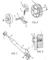
- a centrifugal clutch - as illustrated in Figures 2 and 3 - is inserted between the motor and a gear transmission (comprising shafts, gears, and so on), such clutch consisting of a clutch support body 1, generally acting also as ignition/fan flywheel, two or more clutch heavy friction shoes 2 connected to one another by a return spring 3, a screw 5 for fastening of parts together, a clearance compensating washer 4, and a clutch drum or bowl 6.
- the body 1 is connected with a shaft 10 of an endothermic or i.c. engine (not shown in Figure 2), while the clutch drum 6 is fastened to the tool drive shaft.
- this solution has the drawback of a severe wear caused by the rubbing of the compression washer 4.
- the rubbing between the seat of the friction shoe 2 and the fastening screw 5 can lead to a damage.
- wear is remarkably enlarged in a shaking device for collecting fruits, where large and frequent axial motions of the motor occur in the axial direction (up to 2,000 per minute). Therefore, a scraping axial effect is added to the rotational wear of the friction shoe pressing the drum during the transients.
- An object of the present invention is to overcome the above mentioned drawbacks of the known devices, and more particularly to provide an unhindered rotation of the clutch friction shoes, by avoiding a coupling that could negatively affect the machine operation and cause a wear-and-tear reducing its useful life.
- the invention eliminates the axial and radial plays between the friction shoes and the screw for rotatably securing the friction shoes to the clutch mounting bracket.
- the present invention generally applies to a plurality of portable handheld power tools or implements for use in farming and gardening works, such power tools comprising a motor, a motor housing and a rod carrying an end tool driven by the motor (usually of i.c. type), such motor being located outside the tool and being adapted to be selectively disengaged from the end tool.
- a motor usually of i.c. type
- the motor being located outside the tool and being adapted to be selectively disengaged from the end tool.
- a shaking device for harvesting fruit comprises a housing 12 provided with at least one handle 13, a rod 14 projecting from the housing and equipped with an end tool 11 driven by a motor or engine 15.
- the motor 15 is mounted outside of housing and is connected to an inner drive mechanism of the tool through a clutch 18 according to the invention.
- the centrifugal clutch 18 comprises a clutch support or body 21 connected to the motor shaft 10, to which body there are mounted two or more heavy friction shoes 22 connected to each other by a return spring 23 and rotatably secured to the body 1 by a screw 25.
- the clutch body 21 there are formed seats 29 (one for each friction shoe in the device), adapted to house as many supporting members 27, in particular bearings 27, preferably ball bearings. Besides, a spacing projection 24 is formed in the clutch body on the opposite side of the seat(s).
- a nut 28 is screwed onto the screw 25 and keeps the clutch friction shoes integral with the spacer 24 and the inner ring of bearing 27, thus preventing any rubbing motion between the friction shoes 22 and the fastening screw 25, while an unhindered rotation of the friction shoe 22 is nevertheless ensured by the presence of bearing 27 which is fastened by interference (i.e. forced) to bore 29.
- the spacer 24 can be either an integral part of the friction shoe 2 or a steel bushing separately provided for.
- an improved clutch according to the invention shall be inserted between the motor and the drive mechanism for rotating a shaft at the end of which a nylon cord head is fitted.
- the modifications of other power tools machines to which said device is applicable, such as for instance chain saws, hedge-trimmers and so on, are not illustrated in detail since they are evident to the skilled of the art.
Landscapes
- Engineering & Computer Science (AREA)
- General Engineering & Computer Science (AREA)
- Mechanical Engineering (AREA)
- Harvester Elements (AREA)
- One-Way And Automatic Clutches, And Combinations Of Different Clutches (AREA)
Claims (10)
- Embrayage centrifuge (18) destiné à un outil électrique portable à utiliser pour les travaux agricoles ou de jardinage, comprenant un corps d'embrayage (21) et au moins une semelle de friction (22) fixée à rotation sur ledit corps et adaptée pour engager un tambour d'embrayage (26) lorsqu'il est en rotation, caractérisé en ce que ladite (lesdites) semelle(s) de friction (22) est (sont) fixée(s) audit corps d'embrayage (21) par l'intermédiaire d'un élément de support rotatif (27) logé dans une embase (29) formée dans ledit corps (21).
- Embrayage selon la revendication 1, caractérisé en ce qu'il comprend deux semelles de friction d'embrayage (22) connectées l'une à l'autre par un ressort de rappel (23) et attachées audit corps (21) par une vis (25) passant à travers un alésage formé dans ledit corps d'embrayage (21).
- Embrayage selon les revendications 1 ou 2, caractérisé en ce que ledit au moins un élément de support (27) est un roulement à billes.
- Embrayage selon les revendications 1 à 3, caractérisé en ce qu'il comprend, de plus, une partie d'espacement en saillie (24) formée sur ledit corps d'embrayage (21), sur le côté opposé desdites embases (29).
- Outil électrique portable, tenu à la main, à utiliser dans des travaux d'agriculture ou de jardinage, comprenant un moteur (15), un logement de moteur (12) et une tige (14) portant un outil d'extrémité (11) entraíné par ledit moteur (15), dans lequel ledit moteur (15) peut être désengagé mécaniquement dudit outil d'extrémité (11) par l'intermédiaire d'un embrayage centrifuge (18) comprenant un corps d'embrayage (21) fixé audit moteur (15), corps auquel au moins une semelle de friction d'embrayage (22) est fixée à rotation afin d'engager un tambour d'embrayage (26) attaché à un mécanisme de commande de ladite tige (14), caractérisé en ce que chacune desdites semelles de friction d'embrayage (22) est fixée à rotation sur ledit corps d'embrayage (21) par un élément de support rotatif (27) logé dans une embase (29) formée dans ledit corps (21).
- Outil électrique selon la revendication 5, caractérisé en ce qu'il comprend deux semelles de friction d'embrayage (22) connectées l'une à l'autre par un ressort de rappel (23) et fixées audit corps (21) par une vis (25) passant à travers un alésage formé dans ledit corps d'embrayage (21).
- Outil électrique selon les revendications 5 ou 6, caractérisé en ce que ledit au moins un élément de support (27) est un roulement à billes.
- Outil électrique selon les revendications précédentes 5 à 7, caractérisé en ce qu'il comprend, de plus, une partie d'espacement en saillie (24) formée sur ledit corps d'embrayage, sur le côté opposé desdites embases (29).
- Outil électrique selon les revendications précédentes 5 à 8, caractérisé en ce que ledit élément de support (27) est ajusté à force dans l'embase (29) dudit support (21).
- Outil électrique selon les revendications précédentes 5 à 9, caractérisé en ce que ledit outil électrique est un dispositif de secouage des arbres destiné à la récolte des fruits.
Priority Applications (2)
| Application Number | Priority Date | Filing Date | Title |
|---|---|---|---|
| ES99830688T ES2237074T3 (es) | 1999-11-02 | 1999-11-02 | Herramienta portatil motorizada para trabajos de agricultura o de jardineria. |
| EP99830688A EP1098100B1 (fr) | 1999-11-02 | 1999-11-02 | Outil portatif motorisé pour travaux agricoles ou de jardinage |
Applications Claiming Priority (1)
| Application Number | Priority Date | Filing Date | Title |
|---|---|---|---|
| EP99830688A EP1098100B1 (fr) | 1999-11-02 | 1999-11-02 | Outil portatif motorisé pour travaux agricoles ou de jardinage |
Publications (2)
| Publication Number | Publication Date |
|---|---|
| EP1098100A1 EP1098100A1 (fr) | 2001-05-09 |
| EP1098100B1 true EP1098100B1 (fr) | 2005-03-09 |
Family
ID=8243654
Family Applications (1)
| Application Number | Title | Priority Date | Filing Date |
|---|---|---|---|
| EP99830688A Expired - Lifetime EP1098100B1 (fr) | 1999-11-02 | 1999-11-02 | Outil portatif motorisé pour travaux agricoles ou de jardinage |
Country Status (2)
| Country | Link |
|---|---|
| EP (1) | EP1098100B1 (fr) |
| ES (1) | ES2237074T3 (fr) |
Families Citing this family (1)
| Publication number | Priority date | Publication date | Assignee | Title |
|---|---|---|---|---|
| DE602004026832D1 (de) * | 2004-05-18 | 2010-06-10 | Cifarelli Spa | Tragbares Gerät zum Schütteln von Obstbäumen, insbesondere Olivenbäumen |
Family Cites Families (7)
| Publication number | Priority date | Publication date | Assignee | Title |
|---|---|---|---|---|
| US4006528A (en) * | 1974-11-22 | 1977-02-08 | Kaaz Machinery Co. Ltd. | Portable grass and brush cutter with brake and clutch |
| US4254854A (en) * | 1979-01-08 | 1981-03-10 | Dyneer Corporation | Centrifugal clutch shoe mounting arrangement |
| JPS6045938U (ja) * | 1983-09-06 | 1985-04-01 | 株式会社共立 | 遠心クラツチ |
| DE3738008A1 (de) * | 1987-11-09 | 1989-05-18 | Porsche Ag | Vorrichtung zum antrieb eines kraftfahrzeugs |
| FR2639175B1 (fr) * | 1988-12-06 | 1991-07-26 | Geiver Sa | Appareil vibrateur portatif pour la recolte des fruits |
| DE4300442A1 (de) * | 1993-01-09 | 1994-07-14 | Scheuffele Robert Gmbh Co Kg | Fliehkraftkupplung mit einem eine Nabe aufweisenden Antriebsflansch |
| DE19721747B4 (de) * | 1997-05-24 | 2014-06-05 | Andreas Stihl Ag & Co. | Fliehkörperkupplung |
-
1999
- 1999-11-02 EP EP99830688A patent/EP1098100B1/fr not_active Expired - Lifetime
- 1999-11-02 ES ES99830688T patent/ES2237074T3/es not_active Expired - Lifetime
Also Published As
| Publication number | Publication date |
|---|---|
| EP1098100A1 (fr) | 2001-05-09 |
| ES2237074T3 (es) | 2005-07-16 |
Similar Documents
| Publication | Publication Date | Title |
|---|---|---|
| US4466233A (en) | Mower drive assembly | |
| US4254550A (en) | Lawn trimmer | |
| JPH09155803A (ja) | 動力作業機 | |
| JP5764363B2 (ja) | 捩りダンパ付クラッチ | |
| US5581985A (en) | Safety clutches for self power operated lawn mowers | |
| EP2156067B1 (fr) | Dispositif de retardement pour machine coupante tenue à la main | |
| US3967438A (en) | Rotary mower spindle assembly | |
| KR100416183B1 (ko) | 예초기 | |
| US4333303A (en) | Clutch and brake mechanism | |
| US4048787A (en) | Combination clutch and brake for rotary power mower | |
| EP1098100A1 (fr) | Outil portatif motorisé pour travaux agricoles ou de jardinage | |
| JP3462352B2 (ja) | 遠心クラッチ | |
| US8973721B2 (en) | Braking apparatus | |
| CA2451480C (fr) | Frein d'arbre de prise de force | |
| US5577587A (en) | Centrifugal clutch | |
| EP1922912A1 (fr) | Assemblage de frein | |
| US3918534A (en) | Special clutch for vibration isolated chain saws | |
| US3414094A (en) | Fluid drive for rotary mowers | |
| JPH0233339B2 (fr) | ||
| JPH09262020A (ja) | 刈払機の刈刃装置 | |
| JPH0643549Y2 (ja) | 作業機械用伝動装置 | |
| JP2004150565A (ja) | ブレーキ付きクラッチ装置 | |
| US5014835A (en) | Power work-machine | |
| JPH0751867Y2 (ja) | 刈取用機械の緩衝装置 | |
| JPH0320590Y2 (fr) |
Legal Events
| Date | Code | Title | Description |
|---|---|---|---|
| PUAI | Public reference made under article 153(3) epc to a published international application that has entered the european phase |
Free format text: ORIGINAL CODE: 0009012 |
|
| AK | Designated contracting states |
Kind code of ref document: A1 Designated state(s): ES GR IT |
|
| AX | Request for extension of the european patent |
Free format text: AL;LT;LV;MK;RO;SI |
|
| 17P | Request for examination filed |
Effective date: 20010904 |
|
| AKX | Designation fees paid |
Free format text: ES GR IT |
|
| REG | Reference to a national code |
Ref country code: DE Ref legal event code: 8566 |
|
| GRAP | Despatch of communication of intention to grant a patent |
Free format text: ORIGINAL CODE: EPIDOSNIGR1 |
|
| GRAS | Grant fee paid |
Free format text: ORIGINAL CODE: EPIDOSNIGR3 |
|
| GRAA | (expected) grant |
Free format text: ORIGINAL CODE: 0009210 |
|
| AK | Designated contracting states |
Kind code of ref document: B1 Designated state(s): ES GR IT |
|
| REG | Reference to a national code |
Ref country code: GR Ref legal event code: EP Ref document number: 20050401069 Country of ref document: GR |
|
| REG | Reference to a national code |
Ref country code: ES Ref legal event code: FG2A Ref document number: 2237074 Country of ref document: ES Kind code of ref document: T3 |
|
| PLBE | No opposition filed within time limit |
Free format text: ORIGINAL CODE: 0009261 |
|
| STAA | Information on the status of an ep patent application or granted ep patent |
Free format text: STATUS: NO OPPOSITION FILED WITHIN TIME LIMIT |
|
| 26N | No opposition filed |
Effective date: 20051212 |
|
| PGFP | Annual fee paid to national office [announced via postgrant information from national office to epo] |
Ref country code: ES Payment date: 20091117 Year of fee payment: 11 |
|
| PGFP | Annual fee paid to national office [announced via postgrant information from national office to epo] |
Ref country code: GR Payment date: 20091116 Year of fee payment: 11 |
|
| PG25 | Lapsed in a contracting state [announced via postgrant information from national office to epo] |
Ref country code: IT Free format text: LAPSE BECAUSE OF NON-PAYMENT OF DUE FEES Effective date: 20091102 |
|
| PG25 | Lapsed in a contracting state [announced via postgrant information from national office to epo] |
Ref country code: GR Free format text: LAPSE BECAUSE OF NON-PAYMENT OF DUE FEES Effective date: 20110602 |
|
| PGFP | Annual fee paid to national office [announced via postgrant information from national office to epo] |
Ref country code: IT Payment date: 20091112 Year of fee payment: 11 |
|
| PGRI | Patent reinstated in contracting state [announced from national office to epo] |
Ref country code: IT Effective date: 20110616 |
|
| PGRI | Patent reinstated in contracting state [announced from national office to epo] |
Ref country code: IT Effective date: 20110616 |
|
| REG | Reference to a national code |
Ref country code: ES Ref legal event code: FD2A Effective date: 20131029 |
|
| PG25 | Lapsed in a contracting state [announced via postgrant information from national office to epo] |
Ref country code: ES Free format text: LAPSE BECAUSE OF NON-PAYMENT OF DUE FEES Effective date: 20101103 |