EP1098295A2 - Ultraschallwellenleiter - Google Patents
Ultraschallwellenleiter Download PDFInfo
- Publication number
- EP1098295A2 EP1098295A2 EP00123831A EP00123831A EP1098295A2 EP 1098295 A2 EP1098295 A2 EP 1098295A2 EP 00123831 A EP00123831 A EP 00123831A EP 00123831 A EP00123831 A EP 00123831A EP 1098295 A2 EP1098295 A2 EP 1098295A2
- Authority
- EP
- European Patent Office
- Prior art keywords
- ultrasonic
- ultrasonic waveguide
- ultrasound
- film
- waveguide
- Prior art date
- Legal status (The legal status is an assumption and is not a legal conclusion. Google has not performed a legal analysis and makes no representation as to the accuracy of the status listed.)
- Granted
Links
Images
Classifications
-
- G—PHYSICS
- G01—MEASURING; TESTING
- G01F—MEASURING VOLUME, VOLUME FLOW, MASS FLOW OR LIQUID LEVEL; METERING BY VOLUME
- G01F1/00—Measuring the volume flow or mass flow of fluid or fluent solid material wherein the fluid passes through a meter in a continuous flow
- G01F1/66—Measuring the volume flow or mass flow of fluid or fluent solid material wherein the fluid passes through a meter in a continuous flow by measuring frequency, phase shift or propagation time of electromagnetic or other waves, e.g. using ultrasonic flowmeters
- G01F1/662—Constructional details
-
- B—PERFORMING OPERATIONS; TRANSPORTING
- B06—GENERATING OR TRANSMITTING MECHANICAL VIBRATIONS IN GENERAL
- B06B—METHODS OR APPARATUS FOR GENERATING OR TRANSMITTING MECHANICAL VIBRATIONS OF INFRASONIC, SONIC, OR ULTRASONIC FREQUENCY, e.g. FOR PERFORMING MECHANICAL WORK IN GENERAL
- B06B3/00—Methods or apparatus specially adapted for transmitting mechanical vibrations of infrasonic, sonic, or ultrasonic frequency
-
- G—PHYSICS
- G10—MUSICAL INSTRUMENTS; ACOUSTICS
- G10K—SOUND-PRODUCING DEVICES; METHODS OR DEVICES FOR PROTECTING AGAINST, OR FOR DAMPING, NOISE OR OTHER ACOUSTIC WAVES IN GENERAL; ACOUSTICS NOT OTHERWISE PROVIDED FOR
- G10K11/00—Methods or devices for transmitting, conducting or directing sound in general; Methods or devices for protecting against, or for damping, noise or other acoustic waves in general
- G10K11/18—Methods or devices for transmitting, conducting or directing sound
- G10K11/22—Methods or devices for transmitting, conducting or directing sound for conducting sound through hollow pipes, e.g. speaking tubes
-
- G—PHYSICS
- G10—MUSICAL INSTRUMENTS; ACOUSTICS
- G10K—SOUND-PRODUCING DEVICES; METHODS OR DEVICES FOR PROTECTING AGAINST, OR FOR DAMPING, NOISE OR OTHER ACOUSTIC WAVES IN GENERAL; ACOUSTICS NOT OTHERWISE PROVIDED FOR
- G10K11/00—Methods or devices for transmitting, conducting or directing sound in general; Methods or devices for protecting against, or for damping, noise or other acoustic waves in general
- G10K11/18—Methods or devices for transmitting, conducting or directing sound
- G10K11/24—Methods or devices for transmitting, conducting or directing sound for conducting sound through solid bodies, e.g. wires
-
- G—PHYSICS
- G01—MEASURING; TESTING
- G01N—INVESTIGATING OR ANALYSING MATERIALS BY DETERMINING THEIR CHEMICAL OR PHYSICAL PROPERTIES
- G01N2291/00—Indexing codes associated with group G01N29/00
- G01N2291/02—Indexing codes associated with the analysed material
- G01N2291/028—Material parameters
- G01N2291/02836—Flow rate, liquid level
-
- G—PHYSICS
- G01—MEASURING; TESTING
- G01N—INVESTIGATING OR ANALYSING MATERIALS BY DETERMINING THEIR CHEMICAL OR PHYSICAL PROPERTIES
- G01N2291/00—Indexing codes associated with group G01N29/00
- G01N2291/02—Indexing codes associated with the analysed material
- G01N2291/028—Material parameters
- G01N2291/02881—Temperature
Definitions
- the invention relates to an ultrasonic waveguide for guiding one in a predetermined one Frequency range lying ultrasound signal.
- Such ultrasonic waveguide e.g. used in ultrasonic flowmeters.
- ultrasonic flow meters typically becomes a piezo crystal for an ultrasonic transducer used with which ultrasound signals are generated or ultrasound signals are detected become.
- Piezocrystals can no longer be used above a certain temperature, the so-called Curie temperature (T c ), since above T c there is no ferroelectric or ferromagnetic phase of the crystal, which is a prerequisite for its piezoelectric property.
- T c Curie temperature
- the flowing medium the flow of which is to be measured with the ultrasonic flow measuring device
- T c Curie temperature
- a certain thermal insulation of the ultrasonic transducer from the hot medium is required for reliable operation of the ultrasonic flow measuring device .
- Ultrasonic waveguides are used for such thermal insulation, which on the one hand are intended to ensure the best possible thermal insulation of the ultrasound transducer from the hot medium and on the other hand to ensure that the transmission of the ultrasound signal is as loss-free and undisturbed as possible.
- the ultrasound signal generated by an ultrasound transducer can then be coupled into the flowing medium with such an ultrasound waveguide, while the actual ultrasound transducer is spatially distant from the hot medium and is thermally insulated from it.
- ultrasonic waveguides are used e.g. B. constructions used as described in WO 96/41157.
- the individual rod diameters are each much smaller than the wavelength of the ultrasound signal to be guided.
- the rods fit snugly into a tube that fits the rods provides lateral support and thus provides a compact ultrasonic waveguide.
- conventional construction is problematic in that it is for guiding of ultrasonic signals with very high frequencies of over 1 MHz in diameter Rods of significantly less than 0.1 mm are required.
- the manufacture of such thin Bars are very complicated, time-consuming and costly.
- the task previously derived and shown is by an ultrasound waveguide solved, which is characterized in that the ultrasonic waveguide has a rolled-up film, the layer thickness of which is significantly less than the smallest wavelength of that in the predetermined frequency range Ultrasonic signal is in the film material.
- the damping and interference of an ultrasonic signal in one Ultrasonic waveguides are dependent on its dimensions. Damping and disturbances of the ultrasonic signal in the ultrasonic waveguide essentially stir on scattering and dispersion of the ultrasonic signal.
- the width and the height of the ultrasonic waveguide much less than that Wavelength of the ultrasonic signal in the material of the ultrasonic waveguide. No scatter and no dispersion of the ultrasonic signal are then also closed expect when the ultrasonic waveguide is practically infinitely extended.
- the relevant dimension is the Layer thickness of the film, which must therefore be chosen accordingly small.
- a rod-shaped ultrasonic waveguide is obtained, of the requirements for a practically scatter and dispersion-free ultrasonic line Fulfills.
- adjacent film layers lying directly on top of each other corresponds to the properties of the ultrasound cables such a rolled-up film not that of a corresponding rod from a solid material.
- the ultrasonic waveguide according to the invention When dimensioning the ultrasonic waveguide according to the invention with a rolled up film is therefore first to check what is the maximum frequency has to be guided by the ultrasonic waveguide ultrasonic signal, so that the Layer thickness of the film to be used can be chosen to be correspondingly small, so that scattering and dispersion of the ultrasonic signal in the ultrasonic waveguide be largely suppressed.
- the ultrasonic waveguide according to the invention can be used in all wavelength ranges from the audible spectrum to frequencies above 20 MHz. Preferably is provided, however, in the ultrasonic waveguide according to the invention use a frequency range from 15 kHz to 20 MHz, in which case the Layer thickness of the film is less than 0.1 mm.
- materials for the rolled-up film of the ultrasonic waveguide according to the invention a variety of materials can be used, preferably there is However, foil made of metal and / or ceramic and / or plastic.
- An ultrasonic waveguide according to the invention can already be used with a rolled-up foil alone can be achieved with the specified good line properties. However, it is preferably provided that the film - preferably with a snug fit - into one Tube is inserted.
- the tube stabilizes the ultrasound waveguide and makes it easier its installation in e.g. a device of an ultrasonic flow meter.
- a variety of materials can be used for the tube itself, preferably however, the tube is made of metal.
- An ultrasound transducer is typically at one end of the rolled-up film provided so that ultrasonic signals can be coupled into the ultrasonic waveguide are or ultrasonic signals can be received from the ultrasonic waveguide.
- the Ultrasonic transducers which generally have a piezo crystal, can do this directly be applied to an unprocessed end face of the film layers.
- the ends of the rolled-up film Ultrasonic waveguide are welded.
- Welding with a TIG process Tungsten Inert Gas
- tungsten inert gas welding i.e. by tungsten inert gas welding.
- the Layer thickness of the film changed from the inside out.
- the ultrasonic waveguide several rolled-up foils with different Has layers and / or different materials. With these Measures are achieved so that the emitted by the ultrasonic waveguide Ultrasonic signal shaped in a predetermined manner and thus z. B. certain Applications can be directed or focused accordingly. This possibility is based on the fact that the speed of propagation of the ultrasound signal in the ultrasonic waveguide on the respective impedance and thus, among other things depends on the layer thickness of the respective film layer in which the corresponding Share of the ultrasonic signal is performed. The same applies to the various Velocity of propagation of the ultrasonic signal in different materials.
- the ultrasonic waveguide according to the invention is versatile. Prefers However, the ultrasonic waveguide according to the invention is installed in an ultrasonic flow measuring device instead, with which the flow of a medium at high temperature should be determined.
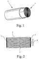
- FIG. 1 schematically shows an ultrasound waveguide according to a preferred embodiment of the invention, which has a rolled-up film 1, which is inserted into a tube 2 with a snug fit.
- both the film 1 as well as the tube 2 made of stainless steel.
- the representation of the ultrasonic waveguide in the 1 is not to scale.
- the layer thickness of film 1 is namely in the present case 0.1 mm, so that even ultrasonic signals with a frequency that is 1 MHz clearly exceeds, are still managed without serious scattering and dispersion effects can.
- the length of the ultrasonic waveguide according to the first preferred embodiment the invention is 0.6 m, and the tube 2 has a wall thickness of 1 mm with an inner diameter of 14 mm. With this ultrasonic waveguide can be damped with an ultrasonic signal with a frequency of 1 MHz of less than 5 dB / m.
- an ultrasonic waveguide according to a preferred embodiment the invention with welded and face-turned ends 3 and one at one these ends 3 coupled ultrasound transducer 4 can be seen.
- TIG welding and then facing the ends of the ultrasonic waveguide an extremely smooth surface is achieved, so that an optimal transfer of the im Ultrasonic transducer 4 generated ultrasonic signals in the ultrasonic waveguide or undisturbed reception of ultrasound signals from the ultrasound waveguide is possible with the ultrasonic transducer 4.
Landscapes
- Physics & Mathematics (AREA)
- Engineering & Computer Science (AREA)
- Acoustics & Sound (AREA)
- Multimedia (AREA)
- Electromagnetism (AREA)
- Fluid Mechanics (AREA)
- General Physics & Mathematics (AREA)
- Mechanical Engineering (AREA)
- Transducers For Ultrasonic Waves (AREA)
- Measuring Volume Flow (AREA)
- Surgical Instruments (AREA)
- Vessels And Coating Films For Discharge Lamps (AREA)
- Investigating Or Analyzing Materials By The Use Of Ultrasonic Waves (AREA)
- Length Measuring Devices Characterised By Use Of Acoustic Means (AREA)
- Superconductors And Manufacturing Methods Therefor (AREA)
- Carbon And Carbon Compounds (AREA)
- Catalysts (AREA)
Abstract
Description
- Fig. 1
- schematisch einen Ultraschallwellenleiter gemäß einem bevorzugten Ausführungsbeispiel der Erfindung und
- Fig. 2
- schematisch einen Ultraschallwellenleiter gemäß einem bevorzugten Ausführungsbeispiel der Erfindung mit angekoppeltem Ultraschalltransducer im Schnitt.
Claims (11)
- Ultraschallwellenleiter zum Führen eines in einem vorbestimmten Frequenzbereich liegenden Ultraschallsignals, dadurch gekennzeichnet, daß der Ultraschallwellenleiter eine zusammengerollte Folie (1) aufweist, deren Schichtdicke wesentlich geringer als die geringste Wellenlänge des in dem vorbestimmten Frequenzbereich liegenden Ultraschallsignals in dem Folienmaterial ist.
- Ultraschallwellenleiter nach Anspruch 1, dadurch gekennzeichnet, daß die Schichtdicke der Folie (1) derart gering gewählt ist, daß beim Führen des Ultraschallsignals in dem Ultraschallwellenleiter Streuung und Dispersion des Ultraschallsignals weitgehend unterdrückt werden.
- Ultraschallwellenleiter nach Anspruch 1 oder 2, dadurch gekennzeichnet, daß der Frequenzbereich 15 kHz bis 20 MHz beträgt.
- Ultraschallwellenleiter nach Anspruch 3, dadurch gekennzeichnet, daß die Schichtdicke der Folie (1) weniger als 0,1 mm beträgt.
- Ultraschallwellenleiter nach einem der Ansprüche 1 bis 4, dadurch gekennzeichnet, daß die Folie (1) aus Metall und/oder Keramik und/oder Kunststoff besteht.
- Ultraschallwellenleiter nach einem der Ansprüche 1 bis 5, dadurch gekennzeichnet, daß die Folie (1) - vorzugsweise mit Paßsitz - in eine - vorzugsweise metallische - Röhre (2) eingesteckt ist.
- Ultraschallwellenleiter nach Anspruch 6, dadurch gekennzeichnet, daß die Enden des Ultraschallwellenleiters verschweißt - vorzugsweise TIG-verschweißt - und plangedreht sind.
- Ultraschallwellenleiter nach einem der Ansprüche 1 bis 7, dadurch gekennzeichnet, daß sich die Schichtdicke der Folie (1) von innen nach außen ändert.
- Ultraschallwellenleiter nach einem der Ansprüche 1 bis 8, dadurch gekennzeichnet, daß der Ultraschallwellenleiter mehrere zusammengerollte Folien (1) mit unterschiedlichen Schichtdicken und/oder unterschiedlichen Materialien aufweist.
- Ultraschallwellenleiter nach einem der Ansprüche 1 bis 9, dadurch gekennzeichnet, daß an einem der beiden Enden der zusammgenrollten Folie (1) ein Ultraschalltransducer (4) derart vorgesehen ist, daß mit diesem Ultraschallsignale in den Ultraschallwellenleiter einkoppelbar und/oder aus dem Ultraschallwellenleiter empfangbar sind.
- Ultraschalldurchflußmeßgerät mit einem Ultraschallwellenleiter nach einem der Ansprüche 1 bis 10.
Applications Claiming Priority (5)
| Application Number | Priority Date | Filing Date | Title |
|---|---|---|---|
| DE19952510 | 1999-11-03 | ||
| DE19952510 | 1999-11-03 | ||
| DE19955165 | 1999-11-16 | ||
| DE19955165 | 1999-11-16 | ||
| US09/706,104 US6400648B1 (en) | 1999-11-03 | 2000-11-03 | Ultrasonic waveguide |
Publications (3)
| Publication Number | Publication Date |
|---|---|
| EP1098295A2 true EP1098295A2 (de) | 2001-05-09 |
| EP1098295A3 EP1098295A3 (de) | 2002-03-13 |
| EP1098295B1 EP1098295B1 (de) | 2004-03-31 |
Family
ID=27219330
Family Applications (1)
| Application Number | Title | Priority Date | Filing Date |
|---|---|---|---|
| EP00123831A Expired - Lifetime EP1098295B1 (de) | 1999-11-03 | 2000-11-02 | Ultraschallwellenleiter |
Country Status (8)
| Country | Link |
|---|---|
| US (1) | US6400648B1 (de) |
| EP (1) | EP1098295B1 (de) |
| JP (1) | JP3666798B2 (de) |
| AT (1) | ATE263411T1 (de) |
| BR (1) | BR0005235A (de) |
| DE (2) | DE10021187C1 (de) |
| DK (1) | DK1098295T3 (de) |
| NO (1) | NO327799B1 (de) |
Cited By (3)
| Publication number | Priority date | Publication date | Assignee | Title |
|---|---|---|---|---|
| DE10153297A1 (de) * | 2001-09-14 | 2003-04-03 | Krohne Ag Basel | Ultraschallwellensende- bzw. -empfangsvorrichtung |
| EP1293960A3 (de) * | 2001-09-14 | 2004-09-08 | Krohne AG | Ultraschallwellensende- bzw. -empfangsvorrichtung mit einem Ultraschallwandler und einem Ultraschallwellenleiter |
| DE10205545B4 (de) * | 2001-11-28 | 2005-09-15 | Krohne Ag | Durchflußmeßgerät |
Families Citing this family (16)
| Publication number | Priority date | Publication date | Assignee | Title |
|---|---|---|---|---|
| DE10021187C1 (de) * | 1999-11-03 | 2001-05-31 | Krohne Ag | Ultraschallwellenleiter |
| US20030212332A1 (en) * | 2002-05-13 | 2003-11-13 | Paul Fenton | Disposable ultrasonic soft tissue cutting and coagulation systems |
| US7156201B2 (en) * | 2004-11-04 | 2007-01-02 | Advanced Ultrasonic Solutions, Inc. | Ultrasonic rod waveguide-radiator |
| GB2431991A (en) | 2005-11-04 | 2007-05-09 | Imp College Innovations Ltd | Waveguide for ultrasonic non-destructive testing |
| US7894306B2 (en) | 2006-12-21 | 2011-02-22 | Bae Systems Plc | Apparatus and method for data transfer through a substrate |
| DE102007027392B3 (de) | 2007-06-11 | 2009-01-15 | Forschungszentrum Dresden - Rossendorf E.V. | Verfahren zur Messung von lokalen Strömungsgeschwindigkeiten in flüssigen Schmelzen |
| DE102007027391B3 (de) * | 2007-06-11 | 2009-01-08 | Forschungszentrum Dresden - Rossendorf E.V. | Ultraschallsensor zur Messung von lokalen Strömungsgeschwindigkeiten in flüssigen Schmelzen |
| US8090131B2 (en) * | 2007-07-11 | 2012-01-03 | Elster NV/SA | Steerable acoustic waveguide |
| DE102007042663A1 (de) | 2007-09-10 | 2009-03-12 | Krohne Ag | Ultraschallsonde |
| US8623040B2 (en) | 2009-07-01 | 2014-01-07 | Alcon Research, Ltd. | Phacoemulsification hook tip |
| WO2011027168A1 (en) * | 2009-09-04 | 2011-03-10 | Bae Systems Plc | Acoustic transmission |
| DE202009014773U1 (de) * | 2009-11-02 | 2011-03-24 | Seuthe, Ulrich | Kopplungselement zur akustischen Ankopplung eines Körpers an einen Schallwandler, Vorrichtung zur Erfassung von Schall |
| DE102009046862A1 (de) | 2009-11-19 | 2011-05-26 | Endress + Hauser Flowtec Ag | Koppelelement eines Sensors eines Ultraschall-Durchflussmessgeräts |
| US10258505B2 (en) | 2010-09-17 | 2019-04-16 | Alcon Research, Ltd. | Balanced phacoemulsification tip |
| GB2495735A (en) * | 2011-10-18 | 2013-04-24 | Bae Systems Plc | Transducer for acoustic communications |
| CA2983655C (en) * | 2015-04-24 | 2022-01-25 | Les Solutions Medicales Soundbite Inc. | Method and system for generating mechanical pulses |
Family Cites Families (6)
| Publication number | Priority date | Publication date | Assignee | Title |
|---|---|---|---|---|
| FR1411069A (fr) * | 1964-07-02 | 1965-09-17 | Realisations Ultrasoniques Sa | Structure permettant la propagation des impulsions élastiques sans échos de falaise |
| JPS54162280A (en) * | 1978-06-13 | 1979-12-22 | Nippon Denshi Kogyo Kk | Transmission cable of ultrasoniccwave device |
| US4337843A (en) * | 1980-07-22 | 1982-07-06 | Electric Power Research Institute, Inc. | Sonic waveguide arrangement using different waveguides and technique for coupling the waveguides together |
| US4392380A (en) * | 1981-02-11 | 1983-07-12 | The United States Of America As Represented By The United States Department Of Energy | High temperature pressure coupled ultrasonic waveguide |
| WO1996041157A1 (en) * | 1995-06-07 | 1996-12-19 | Panametrics, Inc. | Ultrasonic path bundle and systems |
| DE10021187C1 (de) * | 1999-11-03 | 2001-05-31 | Krohne Ag | Ultraschallwellenleiter |
-
2000
- 2000-05-03 DE DE10021187A patent/DE10021187C1/de not_active Expired - Fee Related
- 2000-11-01 JP JP2000334567A patent/JP3666798B2/ja not_active Expired - Fee Related
- 2000-11-01 NO NO20005509A patent/NO327799B1/no not_active IP Right Cessation
- 2000-11-02 AT AT00123831T patent/ATE263411T1/de not_active IP Right Cessation
- 2000-11-02 DE DE50005881T patent/DE50005881D1/de not_active Expired - Lifetime
- 2000-11-02 EP EP00123831A patent/EP1098295B1/de not_active Expired - Lifetime
- 2000-11-02 DK DK00123831T patent/DK1098295T3/da active
- 2000-11-03 US US09/706,104 patent/US6400648B1/en not_active Expired - Lifetime
- 2000-11-06 BR BR0005235-3A patent/BR0005235A/pt not_active IP Right Cessation
Cited By (4)
| Publication number | Priority date | Publication date | Assignee | Title |
|---|---|---|---|---|
| DE10153297A1 (de) * | 2001-09-14 | 2003-04-03 | Krohne Ag Basel | Ultraschallwellensende- bzw. -empfangsvorrichtung |
| DE10153297C2 (de) * | 2001-09-14 | 2003-09-25 | Krohne Ag Basel | Meßgerät |
| EP1293960A3 (de) * | 2001-09-14 | 2004-09-08 | Krohne AG | Ultraschallwellensende- bzw. -empfangsvorrichtung mit einem Ultraschallwandler und einem Ultraschallwellenleiter |
| DE10205545B4 (de) * | 2001-11-28 | 2005-09-15 | Krohne Ag | Durchflußmeßgerät |
Also Published As
| Publication number | Publication date |
|---|---|
| EP1098295A3 (de) | 2002-03-13 |
| BR0005235A (pt) | 2001-08-07 |
| DE50005881D1 (de) | 2004-05-06 |
| NO20005509L (no) | 2001-05-04 |
| JP2001147143A (ja) | 2001-05-29 |
| EP1098295B1 (de) | 2004-03-31 |
| DE10021187C1 (de) | 2001-05-31 |
| ATE263411T1 (de) | 2004-04-15 |
| JP3666798B2 (ja) | 2005-06-29 |
| NO327799B1 (no) | 2009-09-28 |
| NO20005509D0 (no) | 2000-11-01 |
| US6400648B1 (en) | 2002-06-04 |
| DK1098295T3 (da) | 2004-07-26 |
Similar Documents
| Publication | Publication Date | Title |
|---|---|---|
| EP1098295B1 (de) | Ultraschallwellenleiter | |
| DE102019110514B4 (de) | Fluidmesseinrichtung | |
| EP3435041B1 (de) | Messmodul, messeinrichtung und verfahren zur ermittlung einer fluidgrösse | |
| EP2158456B1 (de) | Ultraschallsensor zur messung von strömungsgeschwindigkeiten in flüssigen schmelzen | |
| EP2656017B1 (de) | Koppelelement eines ultraschallwandlers für ein ultraschall-durchflussmessgerät | |
| EP3470799B1 (de) | Messeinrichtung zur ermittlung einer fluidgrösse | |
| EP3521774B1 (de) | Ultraschall-durchflussmessvorrichtung und verfahren zum bestimmen der strömungsgeschwindigkeit | |
| EP3855134B1 (de) | Vorrichtung zur messung der flussgeschwindigkeit eines fluids | |
| DE4415889A1 (de) | Meßwertgeber zur Messung von Flüssigkeitsströmungen mit Ultraschall | |
| EP4182703B1 (de) | Durchflussmessgerät und verfahren zur messung des durchflusses eines fluids | |
| DE10153297A1 (de) | Ultraschallwellensende- bzw. -empfangsvorrichtung | |
| EP1293960A2 (de) | Ultraschallwellensende- bzw. -empfangsvorrichtung mit einem Ultraschallwandler und einem Ultraschallwellenleiter | |
| WO2012084392A1 (de) | Ultraschall-durchflussmessgerät | |
| DE202020104105U1 (de) | Durchflussmessgerät zur Messung des Durchflusses eines Fluids | |
| DE202013105800U1 (de) | Ultraschallmessvorrichtung zum Bestimmen der Strömungsgeschwindigkeit | |
| EP2324933B1 (de) | Koppelelement eines Sensors eines Ultraschall-Durchflussmessgeräts | |
| EP3663728B1 (de) | Messeinrichtung zur ermittlung einer fluidgrösse und verfahren zur herstellung von messeinrichtungen | |
| DE102020126021A1 (de) | Fluidmesseinrichtung | |
| EP2762842A1 (de) | Ultraschallwandler für ein Ultraschalldurchflussmessgerät | |
| EP4242599B1 (de) | Messeinrichtung und verfahren zur ermittlung einer messgrösse | |
| EP3910295B1 (de) | Messeinrichtung zur ermittlung einer fluidgrösse | |
| DE202015106040U1 (de) | System zur Durchflussmessung | |
| EP1046886B1 (de) | Sende- und/oder Empfangskopf eines Ultraschall-Durchflussmessgeräts | |
| EP3889552B1 (de) | Durchflussmessgerät | |
| DE102017009569B4 (de) | Messeinrichtung und Verfahren zur Ermittlung einer Fluidgröße |
Legal Events
| Date | Code | Title | Description |
|---|---|---|---|
| PUAI | Public reference made under article 153(3) epc to a published international application that has entered the european phase |
Free format text: ORIGINAL CODE: 0009012 |
|
| AK | Designated contracting states |
Kind code of ref document: A2 Designated state(s): AT BE CH CY DE DK ES FI FR GB GR IE IT LI LU MC NL PT SE TR |
|
| AX | Request for extension of the european patent |
Free format text: AL;LT;LV;MK;RO;SI |
|
| PUAL | Search report despatched |
Free format text: ORIGINAL CODE: 0009013 |
|
| AK | Designated contracting states |
Kind code of ref document: A3 Designated state(s): AT BE CH CY DE DK ES FI FR GB GR IE IT LI LU MC NL PT SE TR |
|
| AX | Request for extension of the european patent |
Free format text: AL;LT;LV;MK;RO;SI |
|
| RIC1 | Information provided on ipc code assigned before grant |
Free format text: 7G 10K 11/24 A |
|
| 17P | Request for examination filed |
Effective date: 20020912 |
|
| AKX | Designation fees paid |
Free format text: AT BE CH CY DE DK ES FI FR GB GR IE IT LI LU MC NL PT SE TR |
|
| GRAP | Despatch of communication of intention to grant a patent |
Free format text: ORIGINAL CODE: EPIDOSNIGR1 |
|
| GRAS | Grant fee paid |
Free format text: ORIGINAL CODE: EPIDOSNIGR3 |
|
| GRAA | (expected) grant |
Free format text: ORIGINAL CODE: 0009210 |
|
| AK | Designated contracting states |
Kind code of ref document: B1 Designated state(s): AT BE CH CY DE DK ES FI FR GB GR IE IT LI LU MC NL PT SE TR |
|
| PG25 | Lapsed in a contracting state [announced via postgrant information from national office to epo] |
Ref country code: IT Free format text: LAPSE BECAUSE OF FAILURE TO SUBMIT A TRANSLATION OF THE DESCRIPTION OR TO PAY THE FEE WITHIN THE PRESCRIBED TIME-LIMIT;WARNING: LAPSES OF ITALIAN PATENTS WITH EFFECTIVE DATE BEFORE 2007 MAY HAVE OCCURRED AT ANY TIME BEFORE 2007. THE CORRECT EFFECTIVE DATE MAY BE DIFFERENT FROM THE ONE RECORDED. Effective date: 20040331 Ref country code: TR Free format text: LAPSE BECAUSE OF FAILURE TO SUBMIT A TRANSLATION OF THE DESCRIPTION OR TO PAY THE FEE WITHIN THE PRESCRIBED TIME-LIMIT Effective date: 20040331 Ref country code: FI Free format text: LAPSE BECAUSE OF FAILURE TO SUBMIT A TRANSLATION OF THE DESCRIPTION OR TO PAY THE FEE WITHIN THE PRESCRIBED TIME-LIMIT Effective date: 20040331 Ref country code: CY Free format text: LAPSE BECAUSE OF FAILURE TO SUBMIT A TRANSLATION OF THE DESCRIPTION OR TO PAY THE FEE WITHIN THE PRESCRIBED TIME-LIMIT Effective date: 20040331 |
|
| REG | Reference to a national code |
Ref country code: GB Ref legal event code: FG4D Free format text: NOT ENGLISH Ref country code: CH Ref legal event code: EP |
|
| REG | Reference to a national code |
Ref country code: IE Ref legal event code: FG4D Free format text: GERMAN |
|
| REF | Corresponds to: |
Ref document number: 50005881 Country of ref document: DE Date of ref document: 20040506 Kind code of ref document: P |
|
| REG | Reference to a national code |
Ref country code: CH Ref legal event code: NV Representative=s name: KELLER & PARTNER PATENTANWAELTE AG |
|
| GBT | Gb: translation of ep patent filed (gb section 77(6)(a)/1977) |
Effective date: 20040526 |
|
| PG25 | Lapsed in a contracting state [announced via postgrant information from national office to epo] |
Ref country code: GR Free format text: LAPSE BECAUSE OF FAILURE TO SUBMIT A TRANSLATION OF THE DESCRIPTION OR TO PAY THE FEE WITHIN THE PRESCRIBED TIME-LIMIT Effective date: 20040630 Ref country code: SE Free format text: LAPSE BECAUSE OF FAILURE TO SUBMIT A TRANSLATION OF THE DESCRIPTION OR TO PAY THE FEE WITHIN THE PRESCRIBED TIME-LIMIT Effective date: 20040630 |
|
| PG25 | Lapsed in a contracting state [announced via postgrant information from national office to epo] |
Ref country code: ES Free format text: LAPSE BECAUSE OF FAILURE TO SUBMIT A TRANSLATION OF THE DESCRIPTION OR TO PAY THE FEE WITHIN THE PRESCRIBED TIME-LIMIT Effective date: 20040712 |
|
| REG | Reference to a national code |
Ref country code: DK Ref legal event code: T3 |
|
| PG25 | Lapsed in a contracting state [announced via postgrant information from national office to epo] |
Ref country code: LU Free format text: LAPSE BECAUSE OF NON-PAYMENT OF DUE FEES Effective date: 20041102 Ref country code: AT Free format text: LAPSE BECAUSE OF NON-PAYMENT OF DUE FEES Effective date: 20041102 |
|
| ET | Fr: translation filed | ||
| PG25 | Lapsed in a contracting state [announced via postgrant information from national office to epo] |
Ref country code: BE Free format text: LAPSE BECAUSE OF NON-PAYMENT OF DUE FEES Effective date: 20041130 Ref country code: MC Free format text: LAPSE BECAUSE OF NON-PAYMENT OF DUE FEES Effective date: 20041130 |
|
| PLBE | No opposition filed within time limit |
Free format text: ORIGINAL CODE: 0009261 |
|
| STAA | Information on the status of an ep patent application or granted ep patent |
Free format text: STATUS: NO OPPOSITION FILED WITHIN TIME LIMIT |
|
| 26N | No opposition filed |
Effective date: 20050104 |
|
| BERE | Be: lapsed |
Owner name: *KROHNE A.G. Effective date: 20041130 |
|
| BERE | Be: lapsed |
Owner name: *KROHNE A.G. Effective date: 20041130 |
|
| PG25 | Lapsed in a contracting state [announced via postgrant information from national office to epo] |
Ref country code: PT Free format text: LAPSE BECAUSE OF NON-PAYMENT OF DUE FEES Effective date: 20040831 |
|
| PGFP | Annual fee paid to national office [announced via postgrant information from national office to epo] |
Ref country code: NL Payment date: 20111124 Year of fee payment: 12 |
|
| REG | Reference to a national code |
Ref country code: NL Ref legal event code: V1 Effective date: 20130601 |
|
| PG25 | Lapsed in a contracting state [announced via postgrant information from national office to epo] |
Ref country code: NL Free format text: LAPSE BECAUSE OF NON-PAYMENT OF DUE FEES Effective date: 20130601 |
|
| REG | Reference to a national code |
Ref country code: CH Ref legal event code: PCAR Free format text: NEW ADDRESS: EIGERSTRASSE 2 POSTFACH, 3000 BERN 14 (CH) |
|
| REG | Reference to a national code |
Ref country code: FR Ref legal event code: PLFP Year of fee payment: 16 |
|
| REG | Reference to a national code |
Ref country code: FR Ref legal event code: PLFP Year of fee payment: 17 |
|
| REG | Reference to a national code |
Ref country code: FR Ref legal event code: PLFP Year of fee payment: 18 |
|
| PGFP | Annual fee paid to national office [announced via postgrant information from national office to epo] |
Ref country code: IE Payment date: 20191121 Year of fee payment: 20 |
|
| PGFP | Annual fee paid to national office [announced via postgrant information from national office to epo] |
Ref country code: FR Payment date: 20191120 Year of fee payment: 20 Ref country code: DK Payment date: 20191122 Year of fee payment: 20 |
|
| PGFP | Annual fee paid to national office [announced via postgrant information from national office to epo] |
Ref country code: CH Payment date: 20191121 Year of fee payment: 20 |
|
| PGFP | Annual fee paid to national office [announced via postgrant information from national office to epo] |
Ref country code: DE Payment date: 20200120 Year of fee payment: 20 Ref country code: GB Payment date: 20191120 Year of fee payment: 20 |
|
| REG | Reference to a national code |
Ref country code: CH Ref legal event code: PFA Owner name: KROHNE AG, CH Free format text: FORMER OWNER: KROHNE AG, CH |
|
| REG | Reference to a national code |
Ref country code: DE Ref legal event code: R071 Ref document number: 50005881 Country of ref document: DE |
|
| REG | Reference to a national code |
Ref country code: DK Ref legal event code: EUP Expiry date: 20201102 |
|
| REG | Reference to a national code |
Ref country code: CH Ref legal event code: PL |
|
| REG | Reference to a national code |
Ref country code: GB Ref legal event code: PE20 Expiry date: 20201101 |
|
| REG | Reference to a national code |
Ref country code: IE Ref legal event code: MK9A |
|
| PG25 | Lapsed in a contracting state [announced via postgrant information from national office to epo] |
Ref country code: IE Free format text: LAPSE BECAUSE OF EXPIRATION OF PROTECTION Effective date: 20201102 Ref country code: GB Free format text: LAPSE BECAUSE OF EXPIRATION OF PROTECTION Effective date: 20201101 |