EP1098332A2 - Interrupteur limiteur de courant rapide - Google Patents
Interrupteur limiteur de courant rapide Download PDFInfo
- Publication number
- EP1098332A2 EP1098332A2 EP00810942A EP00810942A EP1098332A2 EP 1098332 A2 EP1098332 A2 EP 1098332A2 EP 00810942 A EP00810942 A EP 00810942A EP 00810942 A EP00810942 A EP 00810942A EP 1098332 A2 EP1098332 A2 EP 1098332A2
- Authority
- EP
- European Patent Office
- Prior art keywords
- contact
- switching
- switching point
- current
- switch according
- Prior art date
- Legal status (The legal status is an assumption and is not a legal conclusion. Google has not performed a legal analysis and makes no representation as to the accuracy of the status listed.)
- Granted
Links
Images

Classifications
-
- H—ELECTRICITY
- H01—ELECTRIC ELEMENTS
- H01H—ELECTRIC SWITCHES; RELAYS; SELECTORS; EMERGENCY PROTECTIVE DEVICES
- H01H3/00—Mechanisms for operating contacts
- H01H3/22—Power arrangements internal to the switch for operating the driving mechanism
- H01H3/222—Power arrangements internal to the switch for operating the driving mechanism using electrodynamic repulsion
-
- H—ELECTRICITY
- H01—ELECTRIC ELEMENTS
- H01H—ELECTRIC SWITCHES; RELAYS; SELECTORS; EMERGENCY PROTECTIVE DEVICES
- H01H9/00—Details of switching devices, not covered by groups H01H1/00 - H01H7/00
- H01H9/54—Circuit arrangements not adapted to a particular application of the switching device and for which no provision exists elsewhere
- H01H9/541—Contacts shunted by semiconductor devices
- H01H9/542—Contacts shunted by static switch means
-
- H—ELECTRICITY
- H01—ELECTRIC ELEMENTS
- H01H—ELECTRIC SWITCHES; RELAYS; SELECTORS; EMERGENCY PROTECTIVE DEVICES
- H01H3/00—Mechanisms for operating contacts
- H01H3/22—Power arrangements internal to the switch for operating the driving mechanism
- H01H3/222—Power arrangements internal to the switch for operating the driving mechanism using electrodynamic repulsion
- H01H2003/225—Power arrangements internal to the switch for operating the driving mechanism using electrodynamic repulsion with coil contact, i.e. the movable contact itself forms a secondary coil in which the repulsing current is induced by an operating current in a stationary coil
-
- H—ELECTRICITY
- H01—ELECTRIC ELEMENTS
- H01H—ELECTRIC SWITCHES; RELAYS; SELECTORS; EMERGENCY PROTECTIVE DEVICES
- H01H9/00—Details of switching devices, not covered by groups H01H1/00 - H01H7/00
- H01H9/54—Circuit arrangements not adapted to a particular application of the switching device and for which no provision exists elsewhere
- H01H9/541—Contacts shunted by semiconductor devices
- H01H9/542—Contacts shunted by static switch means
- H01H2009/543—Contacts shunted by static switch means third parallel branch comprising an energy absorber, e.g. MOV, PTC, Zener
-
- H—ELECTRICITY
- H01—ELECTRIC ELEMENTS
- H01H—ELECTRIC SWITCHES; RELAYS; SELECTORS; EMERGENCY PROTECTIVE DEVICES
- H01H33/00—High-tension or heavy-current switches with arc-extinguishing or arc-preventing means
- H01H33/02—Details
- H01H33/04—Means for extinguishing or preventing arc between current-carrying parts
- H01H33/16—Impedances connected with contacts
- H01H33/161—Variable impedances
- H01H2033/163—Variable impedances using PTC elements
Definitions
- the invention is based on a current-limiting switch the preamble of claim 1.
- Such current-limiting switches can be in the high or medium voltage range as a generator switch, as a tie switch between busbar sections in Switchgear, as a DC switch or in meshed networks for reduction of operating losses are used.
- the invention takes on a prior art of current limiting switches reference, as in the as yet unpublished European application EP Registration no. 98811251.2.
- This switch has a quick mechanical switching point with galvanic contacts and two in parallel switched commutation paths.
- the first commutation path are in series a first switching device and an isolating switching point arranged in the second Commutation path are a current limiter and a second switching device in Series switched.
- the current limiter is designed such that it is guided Current, which when opening the first switching device from the first to the second Commutation path is commutated, is limited with a time delay. During this There can be no time delay over the two commutation paths Build up overvoltage and can also be in the first commutation path overvoltage-proof isolating path are formed.
- the object of the invention is as set out in the claims based on a current-limiting switch of the type mentioned create, which thanks to its special, space-saving structure and the small moving mass because of a quick switching on and off in the up and Medium voltage range enabled.
- the current-limiting switch according to the invention has three in parallel to each other arranged paths, two of which contain a mechanical switching point.
- One of these mechanical switching points is for guiding and switching Rated current, while the other is only briefly and when switching through which a commutated current flows.
- the Contact arrangements of the mechanical switching points are axially symmetrical trained and arranged coaxially. Thanks to short, coaxial copper connections there are very small leakage inductances, which results in a very fast Commutation of the currents is made possible.
- the third path of the switch according to the invention also contains a mechanical one Switching point with a coaxially arranged contact arrangement, is unnecessary conventional current-limiting switches in series-connected series isolators.
- This can reduce the dimensions of a housing, in which the contact arrangements are arranged, for example against dust or to be protected from other disruptive influences.
- The is particularly advantageous Arrangement of the contact arrangements in a pressure-resistant housing, which for example with an insulating gas under atmospheric or higher pressure is filled, which is beneficial to the dielectric property of the contact arrangement affects. If the housing contains two electrically conductive, isolated parts, the nominal current can be connected directly to the connections of the Lead nominal current switching point. Elaborate nominal current feedthroughs through the Housing is thus eliminated.
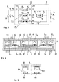
- the circuit shown in Fig. 1 is a single-phase basic circuit of a test device emulating a medium-voltage network with a first embodiment of a current-limiting switch S according to the invention.
- the test device contains a generator Q simulating a mains voltage U N of a few 10 kV, the switch S and a load L simulated from an ohmic resistor R L and an inductor L L.
- a short-circuit current detection unit E is connected between the generator Q and the switch S, which contains a measuring and evaluation part for the very rapid detection of short-circuit currents of up to some 10 kA.
- the switch S has a nominal current switching point S 1 located in the current path from the generator Q to the load L. Two commutation paths P 1 and P 2 are connected in parallel with the nominal current switching point S 1 .
- the first commutation path P 1 contains an isolating switching point S T and a power electronic switching device T with a diode bridge D 1 , D 2 , power semiconductors H that can be switched off, for example GTO, and a surge arrester M.
- the diode bridge allows switching of alternating currents both with positive and with negative Polarity without power semiconductors connected in anti-parallel.
- the second commutation path P 2 connected in series, contains a switch-off switching point S A and a current limiter R B , which responds to a current with a time delay and is designed, for example, as a PTC resistor.
- the switch-off switching point can be designed as a semiconductor switch H A with antiparallel switched, switchable power semiconductors, for example GTOs, or comprise a galvanically isolating mechanical contact arrangement K A , preferably a vacuum switch.
- the switching points S 1 and S T of the switch according to FIG. 1 each have a contact arrangement K 1 and K T that opens very quickly, within a few 100 ⁇ s.
- the contact arrangement K 1 of the nominal current switching point S 1 is arc-proof.
- the two contact arrangements K 1 and K T of the switching points S 1 and S T are arranged in a housing G.
- the two contact arrangements K 1 and K T of the switching points S 1 and S T are connected via a connection 1, a first housing part 10 and primary leads 11 and 12.
- the nominal current switching point S 1 is connected to the connection 2 via a secondary feed line 21 and a second housing part 20.
- the isolating switching point ST of the first commutation path P 1 is connected to the power electronic switching device T via a secondary feed line 31 which is guided through the housing G with a bushing 5 and via a connection 3.
- the contact arrangements K 1 and K T of the two switching points S 1 and S T and the switch-off switching point S A are closed or conductive. If a short-circuit current occurs, the detection unit E triggers a switch-off process at the current-limiting switch S within approximately 100 ⁇ s. The semiconductor elements H lying in the first commutation path P 1 are immediately made conductive. At the same time, the contact arrangement K 1 of the nominal current switching point S 1 is opened. Due to two arcs formed in series, the short-circuit current that is still rising commutates into the first commutation path P 1 within approximately 150 microseconds.
- Fig. 2 shows a possible arrangement of the first embodiment of the switch according to the invention.
- the two switching points S 1 and S T are mostly arranged coaxially symmetrically in a cylindrical housing G.
- the housing G is composed of two plate-shaped, electrically conductive housing parts 10 and 20, a tubular, electrically insulating housing part 7 and two electrically insulating, gas-tight bushings 5 and 6.
- the housing G is designed to be pressure-resistant and filled with a gaseous medium, for example air or SF 6 under atmospheric or higher pressure.
- the two contact arrangements K 1 and K T are arranged one inside the other, the contact arrangement K 1 of the nominal current switching point S 1 , since it requires a corresponding cross section for carrying nominal current, has the largest diameter and is arranged on the outside.
- the contact arrangement K T of the isolating switching point S T through which a commutating current flows only briefly and in a pulse-like manner only when switching, has a correspondingly smaller diameter and is arranged coaxially within the contact arrangement K 1 of the nominal current switching point S 1 . 2, the leads to the contact points are as short and axially symmetrical as possible.
- the arrangement of the second embodiment of the switch according to the invention shown in FIG. 4 largely corresponds to the arrangement of FIG. 2.
- the switch-off switching point S A is arranged coaxially symmetrically in the housing G.
- An advantageous embodiment of the drive of a switching point looks next to one movable bridge contact piece, which is part of the contact arrangement of the switching point is essentially two coils and a power electronic control unit.
- the contact arrangement and the coils are axially symmetrical and arranged coaxially to each other.
- the exact structure of the three switching points will with reference to a section of the arrangement shown in FIG. 2 shown in FIG explained.
- the Contact ring is acted upon by electrodynamic force from the Power electronic control unit fed into the corresponding coil of energy becomes.
- the contact ring can be in the axial direction between the two coils 81 and 82 are moved back and forth while opening the contact arrangement and again conclude.
- the contact ring 85 fitted between the two fixed switching pieces 84 and closes them short.
- the contact ring 85 In the open position of the contact arrangement, the contact ring 85 of held a holding part 83.
Landscapes
- Driving Mechanisms And Operating Circuits Of Arc-Extinguishing High-Tension Switches (AREA)
- Keying Circuit Devices (AREA)
- Control Of Stepping Motors (AREA)
- Relay Circuits (AREA)
- Breakers (AREA)
Applications Claiming Priority (2)
| Application Number | Priority Date | Filing Date | Title |
|---|---|---|---|
| DE19953551A DE19953551C1 (de) | 1999-11-08 | 1999-11-08 | Schneller strombegrenzender Schalter |
| DE19953551 | 1999-11-08 |
Publications (3)
| Publication Number | Publication Date |
|---|---|
| EP1098332A2 true EP1098332A2 (fr) | 2001-05-09 |
| EP1098332A3 EP1098332A3 (fr) | 2003-01-02 |
| EP1098332B1 EP1098332B1 (fr) | 2006-03-22 |
Family
ID=7928211
Family Applications (1)
| Application Number | Title | Priority Date | Filing Date |
|---|---|---|---|
| EP00810942A Expired - Lifetime EP1098332B1 (fr) | 1999-11-08 | 2000-10-12 | Interrupteur rapide limiteur de courant |
Country Status (10)
| Country | Link |
|---|---|
| US (1) | US6535366B1 (fr) |
| EP (1) | EP1098332B1 (fr) |
| JP (1) | JP2001185007A (fr) |
| CN (1) | CN1167093C (fr) |
| AT (1) | ATE321350T1 (fr) |
| AU (1) | AU767295B2 (fr) |
| CA (1) | CA2325008A1 (fr) |
| CZ (1) | CZ299827B6 (fr) |
| DE (2) | DE19953551C1 (fr) |
| ES (1) | ES2261174T3 (fr) |
Cited By (3)
| Publication number | Priority date | Publication date | Assignee | Title |
|---|---|---|---|---|
| EP2189998A1 (fr) | 2008-11-24 | 2010-05-26 | ABB Technology AG | Agencement de commutation de générateur |
| EP2339599A1 (fr) | 2009-12-22 | 2011-06-29 | ABB Research Ltd. | Commutateur et utilisation associée |
| CN103646805A (zh) * | 2013-12-04 | 2014-03-19 | 中国科学院电工研究所 | 一种直流断路器拓扑 |
Families Citing this family (11)
| Publication number | Priority date | Publication date | Assignee | Title |
|---|---|---|---|---|
| DE102005040432A1 (de) * | 2005-08-25 | 2007-03-01 | Rwth Aachen | Strombegrenzender Schalter |
| US10910816B2 (en) * | 2007-06-20 | 2021-02-02 | S&C Electric Company | Fault protection device with group trip delay and method |
| CN104620345B (zh) | 2012-08-27 | 2016-10-26 | Abb瑞士股份有限公司 | 布置用于断开电流的装置 |
| CN104685597B (zh) | 2012-10-05 | 2017-02-15 | Abb 技术有限公司 | 具有堆叠中断器模块的断路器 |
| CN103280763B (zh) * | 2013-02-27 | 2016-12-28 | 国网智能电网研究院 | 一种直流断路器及其实现方法 |
| EP2790285B1 (fr) * | 2013-04-12 | 2020-07-08 | General Electric Technology GmbH | Limiteur de courant |
| US10128625B2 (en) | 2014-11-18 | 2018-11-13 | General Electric Company | Bus bar and power electronic device with current shaping terminal connector and method of making a terminal connector |
| US11424093B2 (en) | 2018-10-24 | 2022-08-23 | The Florida State University Research Foundation, Inc. | Direct current hybrid circuit breaker with reverse biased voltage source |
| US11646575B2 (en) | 2018-10-24 | 2023-05-09 | The Florida State University Research Foundation, Inc. | Direct current hybrid circuit breaker with reverse biased voltage source |
| DE102020110935B3 (de) | 2020-04-22 | 2021-07-01 | Maschinenfabrik Reinhausen Gmbh | Vorrichtung und verfahren zur begrenzung eines kurzschlussstromes in einem laststufenschalter sowie laststufenschalter mit dieser vorrichtung |
| CN116388132B (zh) * | 2023-06-05 | 2023-08-08 | 广东电网有限责任公司广州供电局 | 直流限流器、直流断路器、直流故障限流方法及相关设备 |
Family Cites Families (7)
| Publication number | Priority date | Publication date | Assignee | Title |
|---|---|---|---|---|
| AT374618B (de) * | 1981-11-03 | 1984-05-10 | Naimer H L | Schalteinrichtung |
| JPH08315666A (ja) * | 1995-05-12 | 1996-11-29 | Mitsubishi Electric Corp | 遮断器および遮断装置 |
| US5867356A (en) * | 1997-11-05 | 1999-02-02 | General Electric Company | Current limiting system and method |
| US6051893A (en) * | 1998-10-29 | 2000-04-18 | Mitsubishi Denki Kabushiki Kaisha | Electric power supply system for load |
| EP1014403A1 (fr) * | 1998-12-21 | 2000-06-28 | Asea Brown Boveri AG | Interrupteur limiteur de courant |
| EP1022755B1 (fr) | 1998-12-21 | 2007-01-24 | ABB Schweiz AG | Interrupteur limiteur de courant |
| JP3676638B2 (ja) * | 2000-01-07 | 2005-07-27 | 東芝三菱電機産業システム株式会社 | 電源系統切り替え装置および切り替え方法 |
-
1999
- 1999-11-08 DE DE19953551A patent/DE19953551C1/de not_active Expired - Fee Related
-
2000
- 2000-10-12 AT AT00810942T patent/ATE321350T1/de not_active IP Right Cessation
- 2000-10-12 DE DE50012441T patent/DE50012441D1/de not_active Expired - Lifetime
- 2000-10-12 EP EP00810942A patent/EP1098332B1/fr not_active Expired - Lifetime
- 2000-10-12 ES ES00810942T patent/ES2261174T3/es not_active Expired - Lifetime
- 2000-11-01 CZ CZ20004059A patent/CZ299827B6/cs not_active IP Right Cessation
- 2000-11-01 AU AU69659/00A patent/AU767295B2/en not_active Ceased
- 2000-11-02 JP JP2000336051A patent/JP2001185007A/ja not_active Withdrawn
- 2000-11-02 CA CA002325008A patent/CA2325008A1/fr not_active Abandoned
- 2000-11-08 US US09/708,070 patent/US6535366B1/en not_active Expired - Fee Related
- 2000-11-08 CN CNB001339958A patent/CN1167093C/zh not_active Expired - Fee Related
Cited By (4)
| Publication number | Priority date | Publication date | Assignee | Title |
|---|---|---|---|---|
| EP2189998A1 (fr) | 2008-11-24 | 2010-05-26 | ABB Technology AG | Agencement de commutation de générateur |
| EP2339599A1 (fr) | 2009-12-22 | 2011-06-29 | ABB Research Ltd. | Commutateur et utilisation associée |
| CN103646805A (zh) * | 2013-12-04 | 2014-03-19 | 中国科学院电工研究所 | 一种直流断路器拓扑 |
| CN103646805B (zh) * | 2013-12-04 | 2016-03-02 | 中国科学院电工研究所 | 一种直流断路器拓扑 |
Also Published As
| Publication number | Publication date |
|---|---|
| CA2325008A1 (fr) | 2001-05-08 |
| AU767295B2 (en) | 2003-11-06 |
| EP1098332A3 (fr) | 2003-01-02 |
| ES2261174T3 (es) | 2006-11-16 |
| CN1167093C (zh) | 2004-09-15 |
| AU6965900A (en) | 2001-06-07 |
| US6535366B1 (en) | 2003-03-18 |
| JP2001185007A (ja) | 2001-07-06 |
| CZ20004059A3 (cs) | 2001-10-17 |
| DE19953551C1 (de) | 2001-08-16 |
| ATE321350T1 (de) | 2006-04-15 |
| CZ299827B6 (cs) | 2008-12-10 |
| DE50012441D1 (de) | 2006-05-11 |
| CN1300091A (zh) | 2001-06-20 |
| EP1098332B1 (fr) | 2006-03-22 |
Similar Documents
| Publication | Publication Date | Title |
|---|---|---|
| EP3084960B1 (fr) | Dispositif de commutation pour le passage et la coupure de courants électriques | |
| DE69405339T2 (de) | Elektrische Umschaltung | |
| DE3611270C2 (de) | Elektrische Schalteinrichtung für hohe Schaltspannungen | |
| DE19953551C1 (de) | Schneller strombegrenzender Schalter | |
| DE102016120070A1 (de) | Niederspannungs-Schutzschaltgerät | |
| EP1014403A1 (fr) | Interrupteur limiteur de courant | |
| WO2018046708A1 (fr) | Disjoncteur | |
| DE102017122218A1 (de) | Niederspannungs-Schutzschaltgerät | |
| DE2242696B2 (de) | Schalteinrichtung zum Unterbrechen einer Hochspannungs-Gleichstromleitung | |
| DE4405206A1 (de) | Schaltvorrichtung | |
| DE10016950A1 (de) | Verfahren zum Abschalten eines Kurzschlussstroms im generatornahen Bereich | |
| DE2208432A1 (de) | Leistungsschalter für Hochspannungssysteme | |
| EP3044799B1 (fr) | Unité de séparateur avec entraînement électromagnétique | |
| WO1999017415A1 (fr) | Disjoncteur permettant de fournir et de distribuer de l'energie | |
| DE102011078034A1 (de) | Schaltvorrichtung | |
| DE2026685C3 (de) | Verfahren und Schalteinrichtung zum Unterbrechen von Gleichstrom-Energieübertragungs netzen | |
| DE3705719C2 (fr) | ||
| DE10002870A1 (de) | Vorrichtung zum Begrenzen eines Stromes | |
| EP3050069B1 (fr) | Un dispositif de commutation et procédé de coupure de fonctionnement d'un dispositif de commutation | |
| EP1050058A1 (fr) | Chambre d'interrupteur a vide a isolateur annulaire | |
| EP1022753B1 (fr) | Dispositif de contact pour interupteur limiteur de courant | |
| EP3561972B1 (fr) | Installation d'influence de réseau | |
| DE1017248B (de) | Wechselstromschalteinrichtung | |
| DE102024128671B3 (de) | Hybridschalter und Verfahren zum Steuern eines Hybridschalters | |
| DE102022118372B4 (de) | Anordnung zum Unterbrechen von Strom in einer Hochspannungsleitung und Verfahren zum Betreiben einer solchen Anordnung |
Legal Events
| Date | Code | Title | Description |
|---|---|---|---|
| PUAI | Public reference made under article 153(3) epc to a published international application that has entered the european phase |
Free format text: ORIGINAL CODE: 0009012 |
|
| AK | Designated contracting states |
Kind code of ref document: A2 Designated state(s): AT BE CH CY DE DK ES FI FR GB GR IE IT LI LU MC NL PT SE |
|
| AX | Request for extension of the european patent |
Free format text: AL;LT;LV;MK;RO;SI |
|
| RAP1 | Party data changed (applicant data changed or rights of an application transferred) |
Owner name: ABB SCHWEIZ AG |
|
| PUAL | Search report despatched |
Free format text: ORIGINAL CODE: 0009013 |
|
| AK | Designated contracting states |
Kind code of ref document: A3 Designated state(s): AT BE CH CY DE DK ES FI FR GB GR IE IT LI LU MC NL PT SE |
|
| AX | Request for extension of the european patent |
Free format text: AL;LT;LV;MK;RO;SI |
|
| RIC1 | Information provided on ipc code assigned before grant |
Free format text: 7H 01H 9/54 A |
|
| 17P | Request for examination filed |
Effective date: 20030613 |
|
| AKX | Designation fees paid |
Designated state(s): AT BE CH CY DE DK ES FI FR GB GR IE IT LI LU MC NL PT SE |
|
| GRAP | Despatch of communication of intention to grant a patent |
Free format text: ORIGINAL CODE: EPIDOSNIGR1 |
|
| GRAS | Grant fee paid |
Free format text: ORIGINAL CODE: EPIDOSNIGR3 |
|
| GRAA | (expected) grant |
Free format text: ORIGINAL CODE: 0009210 |
|
| AK | Designated contracting states |
Kind code of ref document: B1 Designated state(s): AT BE CH CY DE DK ES FI FR GB GR IE IT LI LU MC NL PT SE |
|
| PG25 | Lapsed in a contracting state [announced via postgrant information from national office to epo] |
Ref country code: IT Free format text: LAPSE BECAUSE OF FAILURE TO SUBMIT A TRANSLATION OF THE DESCRIPTION OR TO PAY THE FEE WITHIN THE PRESCRIBED TIME-LIMIT;WARNING: LAPSES OF ITALIAN PATENTS WITH EFFECTIVE DATE BEFORE 2007 MAY HAVE OCCURRED AT ANY TIME BEFORE 2007. THE CORRECT EFFECTIVE DATE MAY BE DIFFERENT FROM THE ONE RECORDED. Effective date: 20060322 Ref country code: IE Free format text: LAPSE BECAUSE OF FAILURE TO SUBMIT A TRANSLATION OF THE DESCRIPTION OR TO PAY THE FEE WITHIN THE PRESCRIBED TIME-LIMIT Effective date: 20060322 Ref country code: NL Free format text: LAPSE BECAUSE OF FAILURE TO SUBMIT A TRANSLATION OF THE DESCRIPTION OR TO PAY THE FEE WITHIN THE PRESCRIBED TIME-LIMIT Effective date: 20060322 |
|
| REG | Reference to a national code |
Ref country code: GB Ref legal event code: FG4D Free format text: NOT ENGLISH |
|
| REG | Reference to a national code |
Ref country code: CH Ref legal event code: EP |
|
| REG | Reference to a national code |
Ref country code: IE Ref legal event code: FG4D Free format text: LANGUAGE OF EP DOCUMENT: GERMAN |
|
| REF | Corresponds to: |
Ref document number: 50012441 Country of ref document: DE Date of ref document: 20060511 Kind code of ref document: P |
|
| PG25 | Lapsed in a contracting state [announced via postgrant information from national office to epo] |
Ref country code: DK Free format text: LAPSE BECAUSE OF FAILURE TO SUBMIT A TRANSLATION OF THE DESCRIPTION OR TO PAY THE FEE WITHIN THE PRESCRIBED TIME-LIMIT Effective date: 20060622 Ref country code: SE Free format text: LAPSE BECAUSE OF FAILURE TO SUBMIT A TRANSLATION OF THE DESCRIPTION OR TO PAY THE FEE WITHIN THE PRESCRIBED TIME-LIMIT Effective date: 20060622 |
|
| GBT | Gb: translation of ep patent filed (gb section 77(6)(a)/1977) |
Effective date: 20060612 |
|
| PG25 | Lapsed in a contracting state [announced via postgrant information from national office to epo] |
Ref country code: PT Free format text: LAPSE BECAUSE OF FAILURE TO SUBMIT A TRANSLATION OF THE DESCRIPTION OR TO PAY THE FEE WITHIN THE PRESCRIBED TIME-LIMIT Effective date: 20060822 |
|
| NLV1 | Nl: lapsed or annulled due to failure to fulfill the requirements of art. 29p and 29m of the patents act | ||
| PG25 | Lapsed in a contracting state [announced via postgrant information from national office to epo] |
Ref country code: MC Free format text: LAPSE BECAUSE OF NON-PAYMENT OF DUE FEES Effective date: 20061031 Ref country code: LI Free format text: LAPSE BECAUSE OF NON-PAYMENT OF DUE FEES Effective date: 20061031 Ref country code: CH Free format text: LAPSE BECAUSE OF NON-PAYMENT OF DUE FEES Effective date: 20061031 |
|
| ET | Fr: translation filed | ||
| REG | Reference to a national code |
Ref country code: IE Ref legal event code: FD4D |
|
| REG | Reference to a national code |
Ref country code: ES Ref legal event code: FG2A Ref document number: 2261174 Country of ref document: ES Kind code of ref document: T3 |
|
| PLBE | No opposition filed within time limit |
Free format text: ORIGINAL CODE: 0009261 |
|
| STAA | Information on the status of an ep patent application or granted ep patent |
Free format text: STATUS: NO OPPOSITION FILED WITHIN TIME LIMIT |
|
| 26N | No opposition filed |
Effective date: 20061227 |
|
| REG | Reference to a national code |
Ref country code: CH Ref legal event code: PL |
|
| BERE | Be: lapsed |
Owner name: ABB SCHWEIZ A.G. Effective date: 20061031 |
|
| PG25 | Lapsed in a contracting state [announced via postgrant information from national office to epo] |
Ref country code: AT Free format text: LAPSE BECAUSE OF NON-PAYMENT OF DUE FEES Effective date: 20061012 |
|
| PG25 | Lapsed in a contracting state [announced via postgrant information from national office to epo] |
Ref country code: GR Free format text: LAPSE BECAUSE OF FAILURE TO SUBMIT A TRANSLATION OF THE DESCRIPTION OR TO PAY THE FEE WITHIN THE PRESCRIBED TIME-LIMIT Effective date: 20060623 |
|
| PG25 | Lapsed in a contracting state [announced via postgrant information from national office to epo] |
Ref country code: FI Free format text: LAPSE BECAUSE OF FAILURE TO SUBMIT A TRANSLATION OF THE DESCRIPTION OR TO PAY THE FEE WITHIN THE PRESCRIBED TIME-LIMIT Effective date: 20060322 |
|
| PG25 | Lapsed in a contracting state [announced via postgrant information from national office to epo] |
Ref country code: LU Free format text: LAPSE BECAUSE OF NON-PAYMENT OF DUE FEES Effective date: 20061012 |
|
| PG25 | Lapsed in a contracting state [announced via postgrant information from national office to epo] |
Ref country code: CY Free format text: LAPSE BECAUSE OF FAILURE TO SUBMIT A TRANSLATION OF THE DESCRIPTION OR TO PAY THE FEE WITHIN THE PRESCRIBED TIME-LIMIT Effective date: 20060322 |
|
| PG25 | Lapsed in a contracting state [announced via postgrant information from national office to epo] |
Ref country code: BE Free format text: LAPSE BECAUSE OF FAILURE TO SUBMIT A TRANSLATION OF THE DESCRIPTION OR TO PAY THE FEE WITHIN THE PRESCRIBED TIME-LIMIT Effective date: 20061031 |
|
| PGFP | Annual fee paid to national office [announced via postgrant information from national office to epo] |
Ref country code: DE Payment date: 20101022 Year of fee payment: 11 |
|
| PGFP | Annual fee paid to national office [announced via postgrant information from national office to epo] |
Ref country code: IT Payment date: 20101025 Year of fee payment: 11 Ref country code: GB Payment date: 20101021 Year of fee payment: 11 |
|
| PGFP | Annual fee paid to national office [announced via postgrant information from national office to epo] |
Ref country code: FR Payment date: 20111103 Year of fee payment: 12 Ref country code: ES Payment date: 20111026 Year of fee payment: 12 |
|
| GBPC | Gb: european patent ceased through non-payment of renewal fee |
Effective date: 20121012 |
|
| REG | Reference to a national code |
Ref country code: FR Ref legal event code: ST Effective date: 20130628 |
|
| PG25 | Lapsed in a contracting state [announced via postgrant information from national office to epo] |
Ref country code: GB Free format text: LAPSE BECAUSE OF NON-PAYMENT OF DUE FEES Effective date: 20121012 Ref country code: DE Free format text: LAPSE BECAUSE OF NON-PAYMENT OF DUE FEES Effective date: 20130501 |
|
| REG | Reference to a national code |
Ref country code: DE Ref legal event code: R119 Ref document number: 50012441 Country of ref document: DE Effective date: 20130501 |
|
| PG25 | Lapsed in a contracting state [announced via postgrant information from national office to epo] |
Ref country code: FR Free format text: LAPSE BECAUSE OF NON-PAYMENT OF DUE FEES Effective date: 20121031 Ref country code: IT Free format text: LAPSE BECAUSE OF NON-PAYMENT OF DUE FEES Effective date: 20121012 |
|
| REG | Reference to a national code |
Ref country code: ES Ref legal event code: FD2A Effective date: 20140519 |
|
| PG25 | Lapsed in a contracting state [announced via postgrant information from national office to epo] |
Ref country code: ES Free format text: LAPSE BECAUSE OF NON-PAYMENT OF DUE FEES Effective date: 20121013 |