EP1098335A1 - Capteur pour un couplage par friction utilisant un détecteur de seuil - Google Patents
Capteur pour un couplage par friction utilisant un détecteur de seuil Download PDFInfo
- Publication number
- EP1098335A1 EP1098335A1 EP99121709A EP99121709A EP1098335A1 EP 1098335 A1 EP1098335 A1 EP 1098335A1 EP 99121709 A EP99121709 A EP 99121709A EP 99121709 A EP99121709 A EP 99121709A EP 1098335 A1 EP1098335 A1 EP 1098335A1
- Authority
- EP
- European Patent Office
- Prior art keywords
- sensor
- bearing surfaces
- magnets
- plates
- plate
- Prior art date
- Legal status (The legal status is an assumption and is not a legal conclusion. Google has not performed a legal analysis and makes no representation as to the accuracy of the status listed.)
- Granted
Links
- 230000001960 triggered effect Effects 0.000 claims description 8
- 238000001514 detection method Methods 0.000 claims description 4
- 239000006187 pill Substances 0.000 claims description 4
- 239000003990 capacitor Substances 0.000 claims 1
- 238000005259 measurement Methods 0.000 abstract description 6
- 239000004020 conductor Substances 0.000 abstract description 5
- 238000003860 storage Methods 0.000 description 14
- 238000005299 abrasion Methods 0.000 description 5
- 238000009429 electrical wiring Methods 0.000 description 3
- 239000000463 material Substances 0.000 description 3
- XEEYBQQBJWHFJM-UHFFFAOYSA-N Iron Chemical compound [Fe] XEEYBQQBJWHFJM-UHFFFAOYSA-N 0.000 description 2
- 238000006243 chemical reaction Methods 0.000 description 2
- 238000010586 diagram Methods 0.000 description 2
- 239000011810 insulating material Substances 0.000 description 2
- 238000004519 manufacturing process Methods 0.000 description 2
- BGPVFRJUHWVFKM-UHFFFAOYSA-N N1=C2C=CC=CC2=[N+]([O-])C1(CC1)CCC21N=C1C=CC=CC1=[N+]2[O-] Chemical compound N1=C2C=CC=CC2=[N+]([O-])C1(CC1)CCC21N=C1C=CC=CC1=[N+]2[O-] BGPVFRJUHWVFKM-UHFFFAOYSA-N 0.000 description 1
- 230000002411 adverse Effects 0.000 description 1
- 230000003679 aging effect Effects 0.000 description 1
- 235000013351 cheese Nutrition 0.000 description 1
- 238000010276 construction Methods 0.000 description 1
- 238000013016 damping Methods 0.000 description 1
- 238000006073 displacement reaction Methods 0.000 description 1
- 238000005553 drilling Methods 0.000 description 1
- 230000000694 effects Effects 0.000 description 1
- 230000002996 emotional effect Effects 0.000 description 1
- 238000005516 engineering process Methods 0.000 description 1
- PCHJSUWPFVWCPO-UHFFFAOYSA-N gold Chemical compound [Au] PCHJSUWPFVWCPO-UHFFFAOYSA-N 0.000 description 1
- 239000010931 gold Substances 0.000 description 1
- 229910052737 gold Inorganic materials 0.000 description 1
- 229910052742 iron Inorganic materials 0.000 description 1
- 230000007774 longterm Effects 0.000 description 1
- 239000000314 lubricant Substances 0.000 description 1
- 238000005461 lubrication Methods 0.000 description 1
- 230000010355 oscillation Effects 0.000 description 1
- 239000002245 particle Substances 0.000 description 1
- 230000035515 penetration Effects 0.000 description 1
- 230000000284 resting effect Effects 0.000 description 1
- 238000005096 rolling process Methods 0.000 description 1
- 239000000523 sample Substances 0.000 description 1
- 238000007493 shaping process Methods 0.000 description 1
- 239000011359 shock absorbing material Substances 0.000 description 1
- 239000007779 soft material Substances 0.000 description 1
- 125000006850 spacer group Chemical group 0.000 description 1
- 230000035882 stress Effects 0.000 description 1
Images


Classifications
-
- H—ELECTRICITY
- H01—ELECTRIC ELEMENTS
- H01H—ELECTRIC SWITCHES; RELAYS; SELECTORS; EMERGENCY PROTECTIVE DEVICES
- H01H35/00—Switches operated by change of a physical condition
- H01H35/006—Switches operated by mechanical overload condition, e.g. transmitted force or torque becoming too high
-
- G—PHYSICS
- G01—MEASURING; TESTING
- G01B—MEASURING LENGTH, THICKNESS OR SIMILAR LINEAR DIMENSIONS; MEASURING ANGLES; MEASURING AREAS; MEASURING IRREGULARITIES OF SURFACES OR CONTOURS
- G01B7/00—Measuring arrangements characterised by the use of electric or magnetic techniques
- G01B7/02—Measuring arrangements characterised by the use of electric or magnetic techniques for measuring length, width or thickness
Definitions
- the invention relates to an electrical sensor for detecting a mechanical adhesion to convert it into a electrical switching signal according to the preamble of claim 1 and an apparatus equipped with such a sensor according to the Preamble of claim 12.
- the invention has for its object a wear, Fatigue and aging effects very little, largely maintenance-free and completely lubricant-free electrical sensor to provide detection of mechanical adhesion, touch, being a deflection from the rest position at the interruption at least one current bridge can be recognized.
- an electrical sensor to detect a mechanical frictional connection for conversion the same into an electrical switching signal, comprising two in parallel plates arranged one above the other, with at least one of the plates a plurality of magnets with electrically conductive first bearing surfaces and facing the first race bearing surfaces on the other plate and also attracted electrically by the magnetic fields conductive second bearing surfaces are arranged and between the first and second barrel bearing surfaces are freely movable electrically and magnetically conductive balls are located by the respective magnetic field of the magnet, which strives to insert the balls into the Roll the center of the magnetic lines of force coming from the barrel bearing surfaces exit or enter the same and the magnetic fields with the a self-centering magnetic bearing between the bearing surfaces form, and the two plates parallel and perpendicular to each other are displaceable, the balls with the respectively assigned first and second running bearing surfaces by means of the mechanical frictional connection each form a current bridge, and if there is a vertical one Force component on one of the plates and thus lifting the one plate relative to the other plate due to the lifting of the
- a special embodiment of the invention consists in that both plates are surrounded by a housing, the lower plate arranged stationary in the housing or part of the housing and a centric bore and three electrically conductive against each other on their top and electrically insulated electrically conductive against the lower plate lower barrel-bearing surfaces and three on the lower plate below the lower running bearing surfaces arranged lower magnets, the upper plate is movable, which has three lower bearing surfaces on its underside opposite electrically connected to each other and against the top plate electrically insulated downward facing top Barrel storage areas and three arranged above the upper barrel storage areas has upper magnets, each of the upper magnets so aligned is that it is the opposite magnet of the lower one Magnets attract that on the top plate further a right angle central cylindrical shaft protruding below is attached, which protrudes through the hole in the lower plate and touches the bottom of the lower plate protrudes from the housing, the Movement of the movable plate parallel and perpendicular to the stationary lower plate is b
- the present invention enables a compact, almost wear-free sensor for the detection of mechanical adhesion with low manufacturing effort and to provide from a few components, a triggering of the sensor based on the interruption of a Current bridge can be recognized.
- the invention has a self-centering and smooth probe mechanism for the detection of mechanical adhesion, namely contact which e.g. for the automatic measurement of the thickness and height of test specimens advantageous can be used.
- the moving parts of the sensor do not need any mechanical guidance as well as the moving parts and their storage neither during the movement associated with a lateral deflection nor are subject to sliding friction when the sensor is triggered and after the deflection or release automatically in their rest position return and in this rest position of itself stable, precise and Center free of sliding friction.
- the sensing mechanism of the sensor can be used during the test specimen follow the scanning along a certain path so that the movement of the test specimen need not be interrupted.
- the holding force to be overcome to trigger the sensor is very high good long-term stability, since the sensor according to the invention has no parts contains the sufficiently large compressive, tensile or shear stresses exposed to significant material fatigue can. This is a significant advantage e.g. versus sensors with spring-induced restoring force. Readjustments of the sensor or The force necessary to trigger it can therefore largely be dispensed with.
- the magnets and bodies that are attracted by a magnetic field can with suitable electrical wiring and with suitable shaping their surfaces themselves act as barrel-bearing surfaces, so that the barrel-bearing surfaces with the surfaces of the magnets or the body that through a magnetic field are attracted to collapse.
- Separate running storage areas can be omitted in this case, which is the construction of a simplified sensor according to the invention.
- the magnets are or bodies that are attracted by a magnetic field, immediately even affected by a certain amount of abrasion.
- the balls can be used if necessary, e.g. after reaching one certain degree of wear, very easily and quickly replaced become. Apart from that with the rolling of the balls on the barrel bearing surfaces associated wear, which is a very low abrasion causes, the sensor works completely wear-free.
- FIGS. 1 to 3 The structure of a preferred embodiment of an inventive Sensors with three electrically conductive balls, three pairs of bearing surfaces and three pairs of magnets is shown in FIGS. 1 to 3.
- a disc-shaped upper plate 3 which is triggered or lateral deflection of the sensor is moved, there are three upper magnets 4a, 5a, 6a, which preferably form an equilateral triangle.
- the underside in the area of Magnets 4a, 5a, 6a with three electrically conductive upper bearing surfaces 4, 5, 6 is provided, which are electrically interconnected by means of a conductor track 17 are connected and also form an equilateral triangle (Fig. 2).
- the disc-shaped lower Plate 2 which is triggered or lateral deflection of the sensor remains stationary, three lower magnets 7a, 8a, 9a so that their Positions with those of the upper ones embedded in the upper plate 2 Magnets 4a, 5a, 6a are congruent and therefore also one form an equilateral triangle.
- At the top of the lower plate 2 is one made of insulating material board 16 attached to their Top in the area of the lower magnets 7a, 8a, 9a with three electrical conductive lower barrel bearing surfaces 7, 8, 9 is provided.
- the lower barrel storage areas 7, 8, 9 are preferably against the lower plate 2 and electrically isolated from each other.
- top and bottom magnets are 4a, 5a, 6a, 7a, 8a, 9a not in the upper plate 3 or in the lower plate 2 embedded, but attached to their surface.
- a magnetic field e.g. Iron disks.
- the upper plate 3 is made of one made of electrically conductive material and with the bearing surfaces 4, 5, 6 electrically connected so that the upper plate 3 for electrical Connection of the race-bearing surfaces 4, 5, 6 serves with each other.
- the orientation of the magnets is chosen so that they face each other Tighten opposite magnets in pairs.
- the Orientation of the upper and lower barrel bearing surfaces is chosen so that each of the upper barrel bearing surfaces 4, 5, 6 to the opposite one lower barrel bearing surface 7, 8, 9 and vice versa.
- a right angle to Plate level protruding shaft 13 attached together with the upper Plate 3 forms the sensing mechanism of the sensor and serves to trigger and Deflection forces that act on the tip of the shaft 13 on the to transfer top plate 3.
- the latter has a bore 14.
- the bore 14 does not have the task of serving as a mechanical guide for the shaft 13, and therefore preferably has a diameter that is significantly larger than the diameter of the shaft 13 to be a non-contact and therefore to ensure smooth implementation of the shaft 13.
- an electrically conductive ball 10, 11, 12 made of one material exists, which is attracted by a magnetic field, so that a self-centering magnetic 3-point bearing is present. Because of the electrical The conductivity of the balls 10, 11, 12 are the opposite pairs Bearing surfaces 4 and 7, 5 and 8 as well as 6 and 9 with frictional engagement, i.e.
- each electrically according to the invention connected so that through the bearing surface 4, the ball 10 and the race bearing surface 7 a first current bridge 20, through the race bearing surface 5, the ball 11 and the race bearing surface 8, a second current bridge 21 and through the race bearing surface 6, the ball 12 and the race bearing surface 9 a third current bridge 22 is formed (FIG. 5, FIG. 6).
- the magnets are in 5 and 6 are not shown for reasons of clarity.
- the running bearing surfaces 4, 5, 6, 7, 8, 9 and the balls 10, 11, 12 to improve the electrical contact coated with gold.
- additional treads are between the Balls and the bearing surfaces adjacent to them additional electrically conductive treads arranged.
- An advantage in use of additional treads is that by appropriate choice of Material and the thickness of the additional treads which are used for triggering required force can be changed very easily without the magnets exchange or make other changes.
- Another The advantage of such an arrangement is that through the use of additional treads made of soft or shock-absorbing Material reduces the stiffness of the magnetic bearing or its damping can be improved, e.g. the reaction of the sensor to impacts, To improve oscillations or vibrations.
- the running storage areas remain completely free of abrasion, which is another advantage in use of additional treads, as they are lighter and less worn can be replaced more cheaply than the barrel storage areas.
- the sensor When exposed to a force that exceeds the holding force of the magnets, the Attraction of the magnets opposing force on the tip of the Shaft 13, the sensor is triggered.
- the adhesion is on one or several of the balls 10, 11, 12 canceled.
- the direction of the force on the feeler mechanism is not runs parallel to the axis of the shaft 13, by lifting one or more balls against a tilt of the feeler mechanism the lower plate 2 occur.
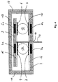
- Fig. 4 shows a cross section through a preferred embodiment of a sensor according to the invention along the one shown in FIGS. 2 and 3 Section A-A.
- the sensor is attached to the lower plate 2 lateral cylindrical wall 18 and a cover 19 provided so that the horizontal and vertical latitude of the top plate 3 and also the angle of the tilt is limited.
- a such an arrangement formed a housing for the magnetic bearing which e.g. the Penetration of dirt is reduced.
- the diameter of the top Plate 3 is expediently smaller in this embodiment. chosen as that of the lower plate 2 to have a certain lateral deflection allow.
- the diameter of the bore 14 is in this Embodiment chosen so large that even with maximum tilt there is no contact between the shaft 13 and the lower plate 2 can to avoid wear due to friction.
- the lid 19 is at least one perpendicular through the interior of the Bracing (not shown) running housing, e.g. a Cylinder screw for applying a tensile force can include lower plate 2 connected to hold the housing together.
- the upper Plate 3 has a corresponding recess in this embodiment 3a (Fig.l) through which the strut runs.
- the through the inside of the Bracing extending along the housing also serves as a lock against one Rotating the upper plate 3 about its axis relative to the lower plate 2 by more than a given angle.
- the balls 10, 11, 12 are either those at the top Plate 3 attached upper barrel bearing surfaces 4, 5, 6 of the deflection follow and lifted along with these, or they stay on the at the lower plate 2 attached lower bearing surfaces 7, 8, 9, each according to whether the holding force of the upper or lower magnet prevails. Because in each case the adhesion and thus the one in question Current bridge is interrupted, it is for the function of the sensor irrelevant which of the two options occurs.
- FIG. 5 is a circuit diagram for a shows preferred embodiment of the invention.
- the upper barrel storage areas are 4, 5, 6 together by an electrical conductor 17 connected.
- the lower barrel bearing surfaces 7, 8 are each one electrical resistance 23, 24, which preferably have different ohmic values have, connected in parallel and to the one pole Voltage source 26 laid.
- the other pole of the voltage source is over one Ammeter 25 connected to the lower barrel bearing surface 9.
- the currents I 1 and I 2 are of different sizes. This means that when the sensor is deflected, a current measurement can be used to clearly determine which of the current bridges 20, 21, 22 is interrupted. This ability of the sensor to differentiate can be advantageous, for example, when scanning test specimens such as pills or tablets with an inclined surface, for example when the orientation of the surface inclination is of interest.
- Fig. 6 shows a circuit diagram for another embodiment of the Invention in which the current bridges 20, 21, 22 are connected in series. As long as there is no triggering of the sensor, all current bridges 20, 21, 22 closed and thus that shown in Fig. 5, by a power source 26 powered circuit closed. In this case, one in the Circuit interposed electrical measuring instrument 25 a Show current flow. As already mentioned above, the frictional connection with the action of a compressive force on the tip of the shaft 13 initially only picked up on one of the balls 10, 11, 12 while being at the others Bullets persists. This means that initially only one of the Current bridges 20, 21, 22 is interrupted. Through this comes the Current flow to a halt, causing the release of the adhesion with Help of the measuring instrument 25 can be recognized. In this embodiment the invention does not matter which of the current bridges 20, 21, 22 is interrupted, and it is also immaterial whether one or several of the current bridges 20, 21, 22 are interrupted.
- FIG. 7 shows an example of an application of a sensor in a Apparatus for measuring the thickness or height of test specimens in cross section.
- a measuring table 35 resting on supports 27, 28 is by means of Spacer sleeves 30, 31, cheese head screws 32, 33 and a mounting plate 34 a stepper motor 29 with threaded spindle (not shown) attached.
- a lifting and lowering mechanism 36, 37 one on this by means of a clamping device 39 attached traverse 40.
- sensor 1 At the Traverse 40 is sensor 1 by means of a further clamping device 41 attached.
- the free end of the shaft 13 is by means of a (not shown) clampable spherical plain bearing with a horizontal stop with a measuring foot 42 provided so that it is pivotable and in particular plane-parallel to Surface of the measuring table 35 can be aligned.
- a test specimen 43 whose thickness or height is to be measured is below the sensor positioned the measuring table. The traverse is included for measurement of the sensor 1 attached to it lowered until one of the current bridges 20, 21, 22 in the sensor 1 is interrupted. The thickness or height of the test specimen results from the number of revolutions of the stepper motor 29 and the pitch of the lead screw.
- a detachable and lockable spherical bearing with which the Housing 1 of the sensor connected via a vertical connecting rod is.
- the connecting rod can be loosened and inside the spherical bearing be moved axially, so that the distance between the sensor and crossbar 40 can be changed.
- One between the top of the Connecting rod and the spherical spring tensioned coil spring is used to pull the sensor away from the measuring table 35 when the spherical bearing is released.
- the measuring foot 42 can thus be pressed against the spring force on the measuring table are and by means of the clampable spherical bearing 41 in the Traverse 40 aligned parallel to the measuring table 35 and in height be adjusted.
- the clampable spherical bearing in the traverse enables on the one hand an axial displacement and on the other hand an inclination of the Sensors. This allows the operator to place the measuring foot on the hand with one hand Press the measuring table plane-parallel against the spring force and use the hold the spherical bearing in place with your other hand. This has the advantage that when Tightening the bearing the sensor is not adjusted again.
- Alternative is a spherical bearing in the measuring foot is also possible.
- the sensor is particularly suitable for measuring the thickness of test specimens, such as Bullets or tablets or pills, industrially applicable. Its usefulness lies in particular in the low response to triggering it, like just a few Newtons, for example already at 2 to 3 Newtons, and in that that it is a self-centering magnetic bearing and therefore the moving part of the sensor always moved back to a rest position and automatically centered there.
Landscapes
- Physics & Mathematics (AREA)
- General Physics & Mathematics (AREA)
- Measurement Of Length, Angles, Or The Like Using Electric Or Magnetic Means (AREA)
- Power Steering Mechanism (AREA)
- Steering Control In Accordance With Driving Conditions (AREA)
- Transmission And Conversion Of Sensor Element Output (AREA)
Priority Applications (3)
| Application Number | Priority Date | Filing Date | Title |
|---|---|---|---|
| AT99121709T ATE333140T1 (de) | 1999-11-02 | 1999-11-02 | Kraftschlussdetektor mit drehmomentschalter |
| DE59913666T DE59913666D1 (de) | 1999-11-02 | 1999-11-02 | Kraftschlussdetektor mit Drehmomentschalter |
| EP99121709A EP1098335B1 (fr) | 1999-11-02 | 1999-11-02 | Capteur pour un couplage par friction utilisant un détecteur de seuil |
Applications Claiming Priority (1)
| Application Number | Priority Date | Filing Date | Title |
|---|---|---|---|
| EP99121709A EP1098335B1 (fr) | 1999-11-02 | 1999-11-02 | Capteur pour un couplage par friction utilisant un détecteur de seuil |
Publications (2)
| Publication Number | Publication Date |
|---|---|
| EP1098335A1 true EP1098335A1 (fr) | 2001-05-09 |
| EP1098335B1 EP1098335B1 (fr) | 2006-07-12 |
Family
ID=8239316
Family Applications (1)
| Application Number | Title | Priority Date | Filing Date |
|---|---|---|---|
| EP99121709A Expired - Lifetime EP1098335B1 (fr) | 1999-11-02 | 1999-11-02 | Capteur pour un couplage par friction utilisant un détecteur de seuil |
Country Status (3)
| Country | Link |
|---|---|
| EP (1) | EP1098335B1 (fr) |
| AT (1) | ATE333140T1 (fr) |
| DE (1) | DE59913666D1 (fr) |
Cited By (2)
| Publication number | Priority date | Publication date | Assignee | Title |
|---|---|---|---|---|
| CN110588422A (zh) * | 2019-09-06 | 2019-12-20 | 北京有感科技有限责任公司 | 自动定位装置、自动定位系统和自动定位方法 |
| CN113530770A (zh) * | 2021-09-03 | 2021-10-22 | 贾星 | 一种风力发电机组叶片的超声波除冰装置 |
Families Citing this family (1)
| Publication number | Priority date | Publication date | Assignee | Title |
|---|---|---|---|---|
| CN108286934B (zh) * | 2018-04-09 | 2020-01-31 | 哈尔滨工程大学 | 一种实现壁面液膜厚度多点实时测量的装置 |
Citations (5)
| Publication number | Priority date | Publication date | Assignee | Title |
|---|---|---|---|---|
| DE3246246A1 (de) * | 1981-12-15 | 1983-06-23 | Tesa S.A., 1020 Renens, Vaud | Potentiometer |
| US4551663A (en) * | 1984-08-01 | 1985-11-05 | Ludlow Industries, Inc. | Level control device |
| DE8904857U1 (de) * | 1989-04-18 | 1989-06-22 | Max Stegmann GmbH, Uhren- und Elektroapparatefabrik, 7710 Donaueschingen | Selbstabschaltender Elektromotor |
| EP0335700A2 (fr) * | 1988-03-30 | 1989-10-04 | Makita Electric Works Ltd | Combinaison d'un interrupteur et d'un dispositif de blocage |
| US5461826A (en) * | 1992-07-10 | 1995-10-31 | Rockwell Body And Chassis Systems | Safety device for electrical openers for a vehicle |
-
1999
- 1999-11-02 EP EP99121709A patent/EP1098335B1/fr not_active Expired - Lifetime
- 1999-11-02 AT AT99121709T patent/ATE333140T1/de not_active IP Right Cessation
- 1999-11-02 DE DE59913666T patent/DE59913666D1/de not_active Expired - Fee Related
Patent Citations (5)
| Publication number | Priority date | Publication date | Assignee | Title |
|---|---|---|---|---|
| DE3246246A1 (de) * | 1981-12-15 | 1983-06-23 | Tesa S.A., 1020 Renens, Vaud | Potentiometer |
| US4551663A (en) * | 1984-08-01 | 1985-11-05 | Ludlow Industries, Inc. | Level control device |
| EP0335700A2 (fr) * | 1988-03-30 | 1989-10-04 | Makita Electric Works Ltd | Combinaison d'un interrupteur et d'un dispositif de blocage |
| DE8904857U1 (de) * | 1989-04-18 | 1989-06-22 | Max Stegmann GmbH, Uhren- und Elektroapparatefabrik, 7710 Donaueschingen | Selbstabschaltender Elektromotor |
| US5461826A (en) * | 1992-07-10 | 1995-10-31 | Rockwell Body And Chassis Systems | Safety device for electrical openers for a vehicle |
Cited By (3)
| Publication number | Priority date | Publication date | Assignee | Title |
|---|---|---|---|---|
| CN110588422A (zh) * | 2019-09-06 | 2019-12-20 | 北京有感科技有限责任公司 | 自动定位装置、自动定位系统和自动定位方法 |
| CN113530770A (zh) * | 2021-09-03 | 2021-10-22 | 贾星 | 一种风力发电机组叶片的超声波除冰装置 |
| CN113530770B (zh) * | 2021-09-03 | 2022-09-09 | 贾星 | 一种风力发电机组叶片的超声波除冰装置 |
Also Published As
| Publication number | Publication date |
|---|---|
| DE59913666D1 (de) | 2006-08-24 |
| ATE333140T1 (de) | 2006-08-15 |
| EP1098335B1 (fr) | 2006-07-12 |
Similar Documents
| Publication | Publication Date | Title |
|---|---|---|
| DE10254229B4 (de) | Positioniervorrichtung zum Positionieren einerAuffangvorrichtung eines Laser-Mikrodissektionssystems | |
| EP2583586B2 (fr) | Dispositif de détection de collisions et procédé associé | |
| EP2078961B1 (fr) | Dispositif de manipulation d'échantillons de laboratoire | |
| DE20010047U1 (de) | Vorrichtung zum Abtasten von Arbeitshöhen | |
| DE102014013883B4 (de) | Bewegungsmechanismus und Formmeßgerät | |
| DE102009036247A1 (de) | Vorrichtung zur Durchführung von Bauteil- und Werkstoffprüfungen an Proben | |
| EP1098335B1 (fr) | Capteur pour un couplage par friction utilisant un détecteur de seuil | |
| DE2553403A1 (de) | Vorrichtung zum feststellen von unebenheiten einer gekruemmten flaeche | |
| EP0093865B2 (fr) | Palpeur pour la détection de coutures | |
| DE3501288C2 (de) | Vorrichtung zum zerstörungsfreien, absoluten Messen von Eigenschaften von festen Stoffen, die aus dem Eindringverhalten eines Prüfkörpers in den Stoff ableitbbar sind | |
| DE3330058A1 (de) | Elektronischer messkopf | |
| DE60126295T2 (de) | Säule zur Messung von longitudinalen Dimensionen | |
| DE9318389U1 (de) | Elektronisches Prüfgerät zur Bestimmung der Härte | |
| DE102022131528B4 (de) | Verfahren und Vorrichtung zur automatischen Gewindeprüfung | |
| DE3831974A1 (de) | Tastkopf | |
| DE2260614B2 (de) | Härteprüfmaschine nach dem Vorlastverfahren nach Rockwell | |
| EP0361518A2 (fr) | Balance du type plate-forme | |
| DE3021357C2 (de) | Elastisches Verbindungsglied zwischen einem Arm und einer Magnethaltevorrichtung eines Handhabungsgerätes | |
| WO2018024496A1 (fr) | Bride de support servant au support mutuel d'un organe de commande et d'un mécanisme de commande et dispositif de mesure | |
| DE19937880A1 (de) | Positionier - und Fördertisch | |
| DE19757567C2 (de) | Einrichtung zur Verstellung des Meßtisches an einem Meßmikroskop | |
| DE3246246A1 (de) | Potentiometer | |
| EP3360653B1 (fr) | Dispositif de préhension pourvu de capteur de champ magnétique externe | |
| DE102004062047B4 (de) | Werkzeugeinstellmessvorrichtung für eine Werkzeugmaschine | |
| DE10329045A1 (de) | Einrichtung zur Ermittlung mindestens einer Endlagenposition eines Antriebsgliedes, insbesondere eines druckmittelbetriebenen Linear- oder Drehantrieb |
Legal Events
| Date | Code | Title | Description |
|---|---|---|---|
| PUAI | Public reference made under article 153(3) epc to a published international application that has entered the european phase |
Free format text: ORIGINAL CODE: 0009012 |
|
| 17P | Request for examination filed |
Effective date: 20000608 |
|
| AK | Designated contracting states |
Kind code of ref document: A1 Designated state(s): AT BE CH CY DE DK ES FI FR GB GR IE IT LI LU MC NL PT SE |
|
| AX | Request for extension of the european patent |
Free format text: AL;LT;LV;MK;RO;SI |
|
| AKX | Designation fees paid | ||
| REG | Reference to a national code |
Ref country code: DE Ref legal event code: 8566 |
|
| RBV | Designated contracting states (corrected) |
Designated state(s): AT BE CH CY DE DK ES FI FR GB GR IE IT LI LU MC NL PT SE |
|
| GRAP | Despatch of communication of intention to grant a patent |
Free format text: ORIGINAL CODE: EPIDOSNIGR1 |
|
| GRAS | Grant fee paid |
Free format text: ORIGINAL CODE: EPIDOSNIGR3 |
|
| GRAA | (expected) grant |
Free format text: ORIGINAL CODE: 0009210 |
|
| AK | Designated contracting states |
Kind code of ref document: B1 Designated state(s): AT BE CH CY DE DK ES FI FR GB GR IE IT LI LU MC NL PT SE |
|
| PG25 | Lapsed in a contracting state [announced via postgrant information from national office to epo] |
Ref country code: NL Free format text: LAPSE BECAUSE OF FAILURE TO SUBMIT A TRANSLATION OF THE DESCRIPTION OR TO PAY THE FEE WITHIN THE PRESCRIBED TIME-LIMIT Effective date: 20060712 Ref country code: IT Free format text: LAPSE BECAUSE OF FAILURE TO SUBMIT A TRANSLATION OF THE DESCRIPTION OR TO PAY THE FEE WITHIN THE PRESCRIBED TIME-LIMIT;WARNING: LAPSES OF ITALIAN PATENTS WITH EFFECTIVE DATE BEFORE 2007 MAY HAVE OCCURRED AT ANY TIME BEFORE 2007. THE CORRECT EFFECTIVE DATE MAY BE DIFFERENT FROM THE ONE RECORDED. Effective date: 20060712 Ref country code: IE Free format text: LAPSE BECAUSE OF FAILURE TO SUBMIT A TRANSLATION OF THE DESCRIPTION OR TO PAY THE FEE WITHIN THE PRESCRIBED TIME-LIMIT Effective date: 20060712 Ref country code: GB Free format text: LAPSE BECAUSE OF FAILURE TO SUBMIT A TRANSLATION OF THE DESCRIPTION OR TO PAY THE FEE WITHIN THE PRESCRIBED TIME-LIMIT Effective date: 20060712 Ref country code: FI Free format text: LAPSE BECAUSE OF FAILURE TO SUBMIT A TRANSLATION OF THE DESCRIPTION OR TO PAY THE FEE WITHIN THE PRESCRIBED TIME-LIMIT Effective date: 20060712 |
|
| REG | Reference to a national code |
Ref country code: GB Ref legal event code: FG4D Free format text: NOT ENGLISH |
|
| REG | Reference to a national code |
Ref country code: CH Ref legal event code: EP |
|
| REG | Reference to a national code |
Ref country code: IE Ref legal event code: FG4D Free format text: LANGUAGE OF EP DOCUMENT: GERMAN |
|
| REF | Corresponds to: |
Ref document number: 59913666 Country of ref document: DE Date of ref document: 20060824 Kind code of ref document: P |
|
| PG25 | Lapsed in a contracting state [announced via postgrant information from national office to epo] |
Ref country code: SE Free format text: LAPSE BECAUSE OF FAILURE TO SUBMIT A TRANSLATION OF THE DESCRIPTION OR TO PAY THE FEE WITHIN THE PRESCRIBED TIME-LIMIT Effective date: 20061012 Ref country code: DK Free format text: LAPSE BECAUSE OF FAILURE TO SUBMIT A TRANSLATION OF THE DESCRIPTION OR TO PAY THE FEE WITHIN THE PRESCRIBED TIME-LIMIT Effective date: 20061012 |
|
| PG25 | Lapsed in a contracting state [announced via postgrant information from national office to epo] |
Ref country code: ES Free format text: LAPSE BECAUSE OF FAILURE TO SUBMIT A TRANSLATION OF THE DESCRIPTION OR TO PAY THE FEE WITHIN THE PRESCRIBED TIME-LIMIT Effective date: 20061023 |
|
| PG25 | Lapsed in a contracting state [announced via postgrant information from national office to epo] |
Ref country code: MC Free format text: LAPSE BECAUSE OF NON-PAYMENT OF DUE FEES Effective date: 20061130 Ref country code: BE Free format text: LAPSE BECAUSE OF NON-PAYMENT OF DUE FEES Effective date: 20061130 |
|
| PG25 | Lapsed in a contracting state [announced via postgrant information from national office to epo] |
Ref country code: PT Free format text: LAPSE BECAUSE OF FAILURE TO SUBMIT A TRANSLATION OF THE DESCRIPTION OR TO PAY THE FEE WITHIN THE PRESCRIBED TIME-LIMIT Effective date: 20061212 |
|
| NLV1 | Nl: lapsed or annulled due to failure to fulfill the requirements of art. 29p and 29m of the patents act | ||
| GBV | Gb: ep patent (uk) treated as always having been void in accordance with gb section 77(7)/1977 [no translation filed] |
Effective date: 20060712 |
|
| REG | Reference to a national code |
Ref country code: IE Ref legal event code: FD4D |
|
| EN | Fr: translation not filed | ||
| PLBE | No opposition filed within time limit |
Free format text: ORIGINAL CODE: 0009261 |
|
| STAA | Information on the status of an ep patent application or granted ep patent |
Free format text: STATUS: NO OPPOSITION FILED WITHIN TIME LIMIT |
|
| 26N | No opposition filed |
Effective date: 20070413 |
|
| BERE | Be: lapsed |
Owner name: LOFFLER, HANS-PETER Effective date: 20061130 |
|
| PGFP | Annual fee paid to national office [announced via postgrant information from national office to epo] |
Ref country code: DE Payment date: 20071018 Year of fee payment: 9 |
|
| PGFP | Annual fee paid to national office [announced via postgrant information from national office to epo] |
Ref country code: CH Payment date: 20071126 Year of fee payment: 9 Ref country code: AT Payment date: 20071123 Year of fee payment: 9 |
|
| PG25 | Lapsed in a contracting state [announced via postgrant information from national office to epo] |
Ref country code: GR Free format text: LAPSE BECAUSE OF FAILURE TO SUBMIT A TRANSLATION OF THE DESCRIPTION OR TO PAY THE FEE WITHIN THE PRESCRIBED TIME-LIMIT Effective date: 20061013 Ref country code: FR Free format text: LAPSE BECAUSE OF FAILURE TO SUBMIT A TRANSLATION OF THE DESCRIPTION OR TO PAY THE FEE WITHIN THE PRESCRIBED TIME-LIMIT Effective date: 20070511 |
|
| PG25 | Lapsed in a contracting state [announced via postgrant information from national office to epo] |
Ref country code: LU Free format text: LAPSE BECAUSE OF NON-PAYMENT OF DUE FEES Effective date: 20061102 |
|
| PG25 | Lapsed in a contracting state [announced via postgrant information from national office to epo] |
Ref country code: FR Free format text: LAPSE BECAUSE OF FAILURE TO SUBMIT A TRANSLATION OF THE DESCRIPTION OR TO PAY THE FEE WITHIN THE PRESCRIBED TIME-LIMIT Effective date: 20060712 Ref country code: CY Free format text: LAPSE BECAUSE OF FAILURE TO SUBMIT A TRANSLATION OF THE DESCRIPTION OR TO PAY THE FEE WITHIN THE PRESCRIBED TIME-LIMIT Effective date: 20060712 |
|
| REG | Reference to a national code |
Ref country code: CH Ref legal event code: PL |
|
| PG25 | Lapsed in a contracting state [announced via postgrant information from national office to epo] |
Ref country code: AT Free format text: LAPSE BECAUSE OF NON-PAYMENT OF DUE FEES Effective date: 20081102 |
|
| PG25 | Lapsed in a contracting state [announced via postgrant information from national office to epo] |
Ref country code: LI Free format text: LAPSE BECAUSE OF NON-PAYMENT OF DUE FEES Effective date: 20081130 Ref country code: DE Free format text: LAPSE BECAUSE OF NON-PAYMENT OF DUE FEES Effective date: 20090603 Ref country code: CH Free format text: LAPSE BECAUSE OF NON-PAYMENT OF DUE FEES Effective date: 20081130 |