EP1098526A2 - Méthode et dispositif d'édition vidéo - Google Patents
Méthode et dispositif d'édition vidéo Download PDFInfo
- Publication number
- EP1098526A2 EP1098526A2 EP00123772A EP00123772A EP1098526A2 EP 1098526 A2 EP1098526 A2 EP 1098526A2 EP 00123772 A EP00123772 A EP 00123772A EP 00123772 A EP00123772 A EP 00123772A EP 1098526 A2 EP1098526 A2 EP 1098526A2
- Authority
- EP
- European Patent Office
- Prior art keywords
- picture
- encoding
- target
- pictures
- range
- Prior art date
- Legal status (The legal status is an assumption and is not a legal conclusion. Google has not performed a legal analysis and makes no representation as to the accuracy of the status listed.)
- Withdrawn
Links
Images


Classifications
-
- H—ELECTRICITY
- H04—ELECTRIC COMMUNICATION TECHNIQUE
- H04N—PICTORIAL COMMUNICATION, e.g. TELEVISION
- H04N21/00—Selective content distribution, e.g. interactive television or video on demand [VOD]
- H04N21/40—Client devices specifically adapted for the reception of or interaction with content, e.g. set-top-box [STB]; Operations thereof
- H04N21/43—Processing of content or additional data, e.g. demultiplexing additional data from a digital video stream; Elementary client operations, e.g. monitoring of home network or synchronising decoder's clock; Client middleware
- H04N21/44—Processing of video elementary streams, e.g. splicing a video clip retrieved from local storage with an incoming video stream or rendering scenes according to encoded video stream scene graphs
- H04N21/44004—Processing of video elementary streams, e.g. splicing a video clip retrieved from local storage with an incoming video stream or rendering scenes according to encoded video stream scene graphs involving video buffer management, e.g. video decoder buffer or video display buffer
-
- H—ELECTRICITY
- H04—ELECTRIC COMMUNICATION TECHNIQUE
- H04N—PICTORIAL COMMUNICATION, e.g. TELEVISION
- H04N19/00—Methods or arrangements for coding, decoding, compressing or decompressing digital video signals
- H04N19/40—Methods or arrangements for coding, decoding, compressing or decompressing digital video signals using video transcoding, i.e. partial or full decoding of a coded input stream followed by re-encoding of the decoded output stream
-
- H—ELECTRICITY
- H04—ELECTRIC COMMUNICATION TECHNIQUE
- H04N—PICTORIAL COMMUNICATION, e.g. TELEVISION
- H04N21/00—Selective content distribution, e.g. interactive television or video on demand [VOD]
- H04N21/20—Servers specifically adapted for the distribution of content, e.g. VOD servers; Operations thereof
- H04N21/23—Processing of content or additional data; Elementary server operations; Server middleware
- H04N21/234—Processing of video elementary streams, e.g. splicing of video streams or manipulating encoded video stream scene graphs
- H04N21/23406—Processing of video elementary streams, e.g. splicing of video streams or manipulating encoded video stream scene graphs involving management of server-side video buffer
Definitions
- the present invention relates to a video editing apparatus, a video editing method, and a medium for storing a video editing program, and relates more particularly to technology for extracting a plurality of contiguous frames (scenes) from a bitstream encoded according to a Motion Picture Expert Group (MPEG) standard, and producing a new bitstream by combining a plurality of the extracted scenes.
- MPEG Motion Picture Expert Group
- MPEG is a family of international standards for encoding moving pictures (hereafter referred to as simply "video"). It includes MPEG-1, which is used for video CD and PC video data, for example, and MPEG-2, which is used with DVD and digital broadcast satellite. Other applications for the MPEG standards continue to be found.
- MPEG has been adopted by the International Standards Organization (ISO) as a standard for a video coding method defining bitstream interpretation and decoding techniques.
- ISO International Standards Organization
- the MPEG-1 standard has been adopted as ISO-11172, and MPEG-2 as ISO-13818.
- MPEG-1 defines a compression technique for compressing and storing video to a digital storage medium with a 1.5 Mbps transfer rate.
- MPEG-2 extends MPEG-1, and defines a compression technique more specifically considering applications with communications and broadcast media, in addition to storage media.
- video data consists of a sequence of picture frames, enabling the pictures to be compressed using correlations within each frame (intra-frame coding) and correlations between frames (inter-frame coding).
- Intra-frame coding correlations within each frame
- inter-frame coding correlations between frames
- I-pictures or intra-coded pictures
- P-pictures or predictive-coded pictures based only on temporally preceding pictures
- B-pictures or bidirectionally predictive-coded pictures.
- I-pictures are coded based solely on the data within that picture frame, and thus have no correlation to any other frame.
- P-pictures are coded with reference (correlation) to a temporally preceding (past) frame.
- B-pictures are coded with correlation to temporally preceding (past) and/or following (future) frames.
- Fig. 13 shows the correlation between pictures in an MPEG-1 bitstream.
- Each square in Fig. 13 represents one picture (frame).
- Each frame is labelled with the picture type and ordinal sequence.
- I indicates an I-picture, P a P-picture, and B a B-picture. Note that this same designation is used throughout the figures and this specification to indicate the picture type.
- the frames are further shown in display order from left to right, and the arrows in Fig. 13 indicate the correlation between frames. For example, from Fig. 13 we know that frame B3 is coded with reference to frames 11 and P4.
- a specific frame can thus be coded with reference to a temporally following (future) frame
- the sequence in which frames are presented (the display order, shown on the top row in Fig. 14) to the viewer and the sequence in which frames are stored on the data storage medium (the coding order or data cumulation order in buffer, shown on the bottom row in Fig. 14) are different in an MPEG-1 bitstream containing B-pictures.
- the MPEG-2 scheme can be applied to picture data having a frame structure or a field structure.
- Video scanning methods include, broadly, non-interlaced scanning and interlaced scanning.
- the video In non-interlaced scanning all pixels in one frame are sampled at the same time.
- the video In this case the video is a collection of frames, and thus has a frame structure.
- each frame in interlaced scan video thus consists of two fields, and the video has a field structure.
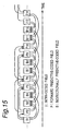
- the picture structure in MPEG-2 video having a frame structure is the same as in MPEG-1. However, picture correlations in field structure video are more complicated. Picture correlations in field structure video are shown in Fig. 15.
- each square represents one field, and the fields are arranged in display order.
- a P-field can be referenced to the most recently decoded I-field, an I-field and a P-field, or to two P-fields.
- the P-field can only use the I-field, which is the first field, for prediction.
- field P2 is coded only with reference to field I1.
- a B-field is coded using the two most recently decoded temporally preceding and following I- and P-fields, that is, two temporally preceding and two temporally following fields.
- field B3 uses preceding fields I1 and P2, and following fields P5 and P6.
- the display order and coding order of field structure video is shown in Fig. 16 on the top and bottom rows, respectively.
- Fig. 17 indicate the correlations between pictures.
- specific scenes that is, pictures B3 to B11
- the links to referenced pictures indicated by the Xs are lost.
- the correlations between pictures I1 and B3, between I1 and P4, and between I13 and B11 are lost.
- picture B3 is coded with reference to picture I1
- picture I1 is not in the extracted sequence from B3 to B11, and picture B3 therefore cannot be reproduced.
- Pictures P4 and B11 also cannot be reproduced for the same reason.
- Fig. 18 (a) shows an idealized decoder, referred to as a system target decoder 2, under the MPEG-1 system, and related peripheral components.
- Encoded MPEG-1 data is input to buffer 1 at a constant bit rate, and data for one decoded picture is read from buffer 1 at a specific decode timing. Picture data is then output either directly or by way of a reordering buffer 3. Differences in the display order and the coding order are absorbed by the reordering buffer 3.
- An MPEG-1 encoder codes video while varying the compression rate to adjust the code size (buffer control) by calculating the buffer capacity needed by the decoder during decoding to prevent both data overflow and data underflow states, that is, the data to be temporarily stored to the decoder buffer exceeds buffer capacity, or the buffer is temporarily depleted because the decoder reads data faster than it is stored to the buffer.
- Fig. 18 (b) shows the change over time in the amount of data stored temporarily to the buffer (buffer fullness).
- the buffer fullness line drops perpendicularly to the x-axis in Fig. 18 (b) (i.e., has a slope of - ⁇ ) indicates when one picture is read from the buffer 1 by system target decoder 2.
- the height of the vertical drop in this line is indicative of the code size of one picture.
- the code size depends on the picture type where I-picture > P-picture > B-picture.
- Data is input to the buffer 1 at a constant rate (slope is a constant positive value) in the periods between when the decoder reads picture data from the buffer.
- the buffer 1 of decoder 2 will neither overflow nor underflow when decoding buffer-controlled MPEG-1 data. However, if the video bitstream is edited without considering this, the buffer control provided for during encoding will be disrupted, buffer overflow and underflow states will be possible, and the requirements of the MPEG-1 standard will no longer be satisfied.
- the second task of the related art is therefore that buffer overflow or underflow states can occur.
- Fig. 19 shows the change in data stored to buffer 1 when scenes 1 and 2 are extracted from a continuous MPEG-1 stream and simply spliced together.
- Fig. 19 (a) shows the change in data before this editing process
- Fig. 19 (b) shows the change after editing. If scenes 1 and 2 are simply spliced together such that storing scene 2 data starts from the end of scene 1, the buffer will overflow as indicated by the X in Fig. 19 (b).
- Data can be coded using either a variable or a constant bit rate in the MPEG-2 standard.
- decoder 2 buffer overflow and underflow states are prohibited when coding with a constant bit rate (CBR).
- VBR variable bit rate
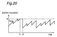
- the vbv_delay value written to the picture header of VBR coded video is set to 0xFFFF (note that the C language convention of using the 0x prefix to indicate hexadecimal code is followed in this specification), and data is input to the buffer under the following conditions.
- Condition 1 If the buffer is not full, data is input to the buffer at the highest bit rate Rmax.
- Condition 2 If the buffer is full, data input to the buffer pauses until a predetermined amount of data is removed from the buffer.
- buffer overflow states are intrinsically avoided, and it is therefore only necessary to consider preventing data underflow states.
- Fig. 20 shows the change in buffer fullness with VBR coded data. If the buffer capacity is B in Fig. 20, data is input to the buffer at highest bit rate Rmax as long as buffer fullness is less than or equal to B. Once the buffer becomes full at time t1, data input to the buffer stops until data is removed from the buffer at time t2, i.e., data input stops from time t1 to time t2.
- Japanese Patent Laid-open Publication ( kokai ) 10-164592 proposes technology for resolving the above tasks 1 and 2.
- Kokai 10-164592 teaches a method for extracting a plurality of frames (scenes) from an MPEG video stream, and connecting a plurality of these scenes to produce a new video stream. The present explanation continues below referring to the technology disclosed in Kokai 10-164592 as prior art.
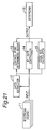
- Fig. 21 a block diagram of a video editor according to the related art.
- data extractor 12 extracts the frame information for each scene from the bitstream 11. Using this frame information, a control point determining means 13 determines the frame (or group of frames) for which the code size is to change, and code size calculator 15 determines the code size (amount of data) to be allocated to the selected frame (or group of frames).
- the bit rate controller 14 then codes the data using the code size thus allocated to this frame (or group) and links the data for the scene to generate a new bitstream 16.
- data extractor 12 sends the frame composition of each scene (that is, the picture types in the scene) to the control point determining means 13.
- control point determining means 13 determines whether there is a frame at the beginning or end of the scene that must be re-encoded in order to sustain the picture content at the beginning and end of the scene, and defines any such frame as a variable bit rate frame. That is, if a picture referenced to code a particular frame in the display order is not included in the group of frames constituting the scene, that particular frame is designated a variable bit rate frame to be re-encoded with a different code size. If there is a plurality of consecutive variable bit rate frames, these frames are treated as a variable bit rate frame group.
- the control point determining means 13 sends information about the variable bit rate frame (group) to code size calculator 15.
- the code size calculator 15 also gets from data extractor 12 such frame information as the bit rate of the bitstream, the buffer size, and the size of the frames in the scene or the frame vbv_delay value.
- the original bitstream data is used for all frames other than the selected variable bit rate frame (group), and these frames are referred to as original data frames.
- the code size calculator 15 also obtains, from the frame information passed from data extractor 12, the initial buffer fullness, final buffer fullness, and highest and lowest buffer fullness values for the buffer in the original data frame range.
- the code size calculator 15 calculates the range in the newly generated bitstream in which these initial and final buffer fullness values of the original data range are possible. This range is calculated for all scenes.
- the code size calculator 15 determines the code size (target code size) allocated to all variable bit rate frames (group) so that the code size remains within this range.
- bit rate controller 14 re-encodes each of the variable bit rate frames to I-pictures based on the target code size allocated to each variable bit rate frame by code size calculator 15. It is also detected at this time whether coding to an I-picture is possible using the target code size. If not, a number of P-pictures with a difference of 0 is inserted, and the increased code size is added to the target code size of the variable bit rate frame. After thus re-encoding the variable bit rate frames, scene data is relinked to produce a new bitstream.
- Buffer fullness is analyzed for every picture in a scene in order to calculate the code size of the re-encoded pictures. Depending on the scene length, this may require processing a large amount of data.
- I-pictures All re-encoded pictures are I-pictures. I-pictures consume a large amount of code. Coding efficiency thus drops.
- Code size is evenly allocated to plural re-encoded pictures at the point the scenes are edited. If there are many re-encoded pictures and a small amount of code is allocated, picture degradation propagates and the quality of the entire video sequence drops.
- the object of the present invention is therefore to provide technology resolving the first and second tasks described above as well as the above-noted problems 1 to 5.
- a video editor has a scene information input means for inputting scene information, where a scene is a plurality of consecutive frames extracted from an edit stream; a re-encoding target picture selector for selecting as target pictures for re-encoding the smallest number of pictures that must be re-encoded for the scene to be independently reproducible; a stream structure data generator for generating structure information for the stream range containing a target picture and an intra-coded picture referenced for coding the target picture; a buffer fullness calculating means for calculating, from stream structure data, buffer fullness, or buffer occupancy, at a target picture boundary to a recycled picture not requiring re-encoding; a re-encoding range code allocation calculator for calculating a code allocation to a re-encoding range based on buffer fullness and target picture count, said re-encoding range being one or a plurality of target pictures near an edit point between scenes; a re-encoding target picture target code
- the video editor of the invention further preferably has a re-encoding target picture type determining means for deciding, from stream structure data, a target picture picture type after re-encoding; and a picture re-encoding means for target picture re-encoding based on target picture target code size and picture type after re-encoding.
- the video editor of the invention further preferably has a code allocation verifying means for verifying whether the code allocation is appropriate based on the re-encoding range code allocation and target picture picture type after re-encoding; and a re-encoding range expanding means for extending the re-encoding range if the code allocation is not appropriate.
- the video editor of the invention preferably has a re-encoding target picture importance calculating means for calculating an importance rating for each target picture in the re-encoding range.
- the video editor of the invention further preferably has a buffer fullness analyzing means for analyzing buffer fullness change when the edit stream is variable bit rate coded and calculating buffer fullness is difficult.
- a video editing apparatus and method according to the present invention combine a scene 1 and a scene 2 to produce a new bitstream as shown in Fig. 12 (a) and (b).
- Scene a picture sequence containing a plurality of consecutive frames for editing.
- Extracted first picture the picture, that is, the frame, located at the beginning of an extracted scene (frame Fs in Fig. 12).
- Extracted last picture the picture, that is, the frame, located at the end of an extracted scene (frame Fe in Fig. 12).
- Re-encoded picture One or a plurality of encoded pictures at the beginning of the extracted scene, or one or a plurality of encoded pictures at the end of the extracted scene, that is decoded and then re-encoded. Also referred to as "target picture.” These pictures are indicated by the solid black blocks in Fig. 12.
- Recycled picture Any encoded picture located in the extracted scene between the first target picture and the last target picture that is used in the edited bitstream as encoded in the original bitstream. These pictures are indicated by the white squares in Fig. 12.
- Recycled picture range The range of frames containing the recycled pictures. See Fig. 12.
- scene information input means 101 passes information about the extracted scene, the extracted scene being a plurality of consecutive frames specified by the operator for extraction from the bitstream for editing (referred to below as the edit stream).
- the re-encoding target picture selector 102 selects and labels as target pictures the smallest number of pictures that must be re-encoded so that the extracted scene can be independently reproduced, that is, reproduced without reference to any picture not contained within the scene.
- the stream structure data generator 103 produces information about the structure of the bitstream in the range containing the target pictures and any intra-coded pictures referenced for coding the target pictures.
- the re-encoding target picture type determining means 104 uses the stream structure information to determine the picture type (I-picture, P-picture, B-picture) of the target picture after it is re-encoded.
- the buffer fullness analyzing means 105 analyzes the change in buffer fullness based on the stream structure data when the edit stream is VBR coded and calculating buffer fullness is difficult.
- buffer fullness calculating means 106 calculates the buffer fullness at the boundary between target pictures and recycled pictures not needing re-encoding.
- Re-encoding range code allocation calculator 107 calculates the amount of code to allocate to the re-encoding range based on the buffer fullness and number of target pictures.
- the re-encoding range as used herein is a range of pictures bracketing the edit position between scenes, specifically containing one or a plurality of target pictures at the end of the scene temporally preceding the edit position, and one or a plurality of target pictures at the beginning of the scene following the edit position.
- the re-encoding range code allocation calculator 107 calculates the amount of code to allocate to the re-encoding range based on the buffer fullness and number of target pictures to be re-encoded where the re-encoding range contains one or more target pictures in proximity to the point where the two scenes are joined.
- the code allocation verifying means 108 verifies whether code allocation T is appropriate in terms of amount based on the picture type of the target pictures after re-encoding and the code allocation for the re-encoding range.
- Re-encoding range expanding means 109 expands the re-encoding range when code allocation T is not appropriate.
- Re-encoding target picture importance calculating means 110 determines the importance of each target picture in the re-encoding range.
- Re-encoding target picture target code size calculating means 111 calculates the amount of code to allocate to each target picture based on the calculated importance rating of each target picture, the code allocation for the re-encoding range, the number of target pictures, and the picture type after re-encoding. Note that target picture importance is not always needed for this calculation.
- Picture re-encoding means 112 re-encodes the target pictures based on the calculated target picture code size and picture type after re-encoding.
- Scene linking means 113 then links the scenes and generates a new bitstream.
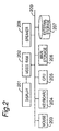
- Fig. 2 is a block diagram showing the hardware configuration of the same apparatus.
- CPU 205 controls operation of peripheral devices according to a control program stored, for example, in external storage 207.
- the peripheral devices including in Fig. 2 display 201, video RAM 202, mouse 203, keyboard 204, main storage 206, external storage 207, and speaker 208 are interconnected by bus 209.
- Video RAM 202 stores the picture data presented on display 201.
- the keyboard 204 inputs to CPU 205 key codes corresponding to the keys operated by the user.
- mouse 203 inputs a code corresponding to the operated button to the CPU 205; when mouse 203 is moved, it inputs a code corresponding to the movement.
- the various means 101 to 113 shown in Fig. 1 are accomplished by the CPU 205 appropriately controlling these peripheral devices and running the control program.
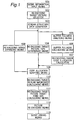
- Fig. 3 is a flow chart of the general video editing process according to the present invention and described below.
- the first step (step 1) is inputting the scene information, which is accomplished by the operator using the scene information input means 101 to select the desired scene, that is, a plurality of consecutive frames to be extracted from the original bitstream for editing.
- the re-encoding target picture selector 102 determines the target pictures by detecting the smallest number of target pictures that must be re-encoded in order for the extracted scene to be independently reproducible (step 2).
- the stream structure data generator 103 then produces information about the structure of the bitstream in the range containing the target pictures and any intra-coded pictures referenced for coding the target pictures (step 3), and the re-encoding target picture type determining means 104 then determines the picture type of the target picture(s) after they are re-encoded (step 4).
- buffer fullness analyzing means 105 analyzes the change in buffer fullness (step 6). If not, the procedure skips to step 7.
- the buffer fullness calculating means 106 calculates the buffer fullness at the boundary between target pictures and recycled pictures not needing re-encoding (step 7), and re-encoding range code allocation calculator 107 calculates the amount of code to allocate to the re-encoding range based on the buffer fullness and number of target pictures (step 8).
- the code allocation verifying means 108 verifies whether code allocation T is appropriate in terms of amount based on the picture type of the target pictures after re-encoding and the code allocation for the re-encoding range (that is, whether VBV_tail is sufficiently greater than VBV_head as further described below) (step 9). If the code allocation T is not appropriate, the re-encoding range is extended (step 10), and the procedure loops back to step 4.
- re-encoding target picture importance calculating means 110 determines the importance of each target picture in the re-encoding range (step 11).
- the re-encoding target picture target code size calculating means 111 then calculates the code allocation for each target picture based on the detected importance of each target picture, the code allocation for the re-encoding range, the number of target pictures, and the picture type after re-encoding (step 12).
- the picture re-encoding means 112 then re-encodes the target pictures based on the calculated target picture code size and picture type after re-encoding (step 13), and finally scene linking means 113 links the scenes to produce a new bitstream (step 14).
- the scene information is input in step 1 by means of scene information input means 101.
- This scene information identifies the plural consecutive frames to be extracted from the bitstream to be edited.
- scene information includes the number of scenes to be linked, the sequence in which they are linked, the extracted picture information, and the output file name.
- the extracted picture information is the connected content and information identifying the interval containing the content, and include the content file name, the byte position of the first extracted picture, and the byte position of the last extracted picture.
- the first extracted picture means the picture that comes at the beginning of the extracted scene
- the last extracted picture means the picture that comes at the end of the extracted scene.
- the number of extracted picture information entries is the same as the number of extracted pictures.
- the output file name is the name of the file to which the new bitstream generated by linking the edited scenes is output in step 14.
- the re-encoding target picture selector 102 determines the target pictures by detecting the smallest number of pictures that must be re-encoded in order for the extracted scene to be independently reproducible. It also identifies the range of frames containing the recycled pictures, that is, the range of pictures that is encoded in the new bitstream using the original data; this is referred to below as the recycled picture range. The identified target pictures are re-encoded in step 13, and the recycled picture range encoded in the new bitstream using the original data.
- Target pictures must be identified at the beginning and end of the scene in order for the scene to be independently reproducible. A method for identifying the target pictures in this step is described below for pictures at the beginning of the scene and at the end.
- Identifying target pictures at the beginning of the scene is described first below. If the first extracted picture is an I-picture, the target picture is only the first extracted picture, and the first picture in the recycled picture range is the first I-picture or P-picture found by searching forward from the first extracted picture.
- forward as used herein means in the direction of the next picture in the temporal direction as indicated by the arrow in Fig. 4;
- reverse or “back” as used herein means in the direction of the previous picture in the temporal direction as indicated by the arrow in Fig. 5; and searching is accomplished in the coding order.
- the target picture is only the first extracted picture
- the first picture in the recycled picture range is the first I-picture or P-picture found by searching forward from the first extracted picture.
- the target pictures include the first extracted picture and the first I-picture or P-picture found by searching backward from the first extracted picture, and all pictures between the first extracted picture and the picture immediately temporally before the first I-picture or P-picture found by searching forward from the first extracted picture.
- the first picture in the recycled picture range is the first I-picture or P-picture found by searching forward from the first extracted picture.
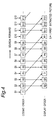
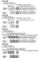
- FIG. 4 Pictures are shown on the top row in Fig. 4 in the coding order, and on the bottom row in display order.
- the first extracted pictures in Fig. 4 are indicated by indices S1 to S12.
- the re-encoding target picture, the picture count, and the first picture in the recycled picture range selected for pictures S1 to S12 are shown in the following table.
- the first extracted picture is picture S5 in Fig. 4, the corresponding target pictures are P4, B5, and B6, and the first picture in the recycled picture range is P7.
- pictures P4, B5, and B6 are re-encoded, and picture P7 and later in the coding orde. are recycled with the original picture data.
- picture P4 is re-encoded to an I-picture, for example, and pictures B5 and B6 are dropped because they are before picture P4 in the display order.
- the last extracted picture is an I-picture, there is no target picture, and the last picture in the recycled picture range is the picture immediately temporally preceding the first I-picture or P-picture found by searching forward from the last extracted picture.
- the last extracted picture is a P-picture, there is no target picture, and the last picture in the recycled picture range is the picture immediately temporally preceding the first I-picture or P-picture found by searching forward from the last extracted picture.
- the target pictures are the pictures including from the last extracted picture to the picture immediately temporally following (future) the first I-picture or P-picture found by searching backward from the last extracted picture.
- the last picture in the recycled picture range is the first picture immediately temporally before (past) the first I-picture or P-picture found by searching backward from the last extracted picture.
- Last extracted picture No. of re-encoded pictures Re-encoded pictures
- Last picture in recycled picture range E 4 0 B 6 E 5 1 B 5 B 3 E 6 2 B 5, B 6 B 3 E 7 0 B 9 E 8 1 B 8 B 6 E 9 2 B 8, B 9 B 6 E10 0 B 1 2 E 1 1 1 B 1 1 B 9 E12 2 B 1 1, B 1 2 B 9
- the target picture for last extracted picture E5 is B5, and the picture B3 is the end of the recycled picture range.
- picture B5 is re-encoded to an I-picture or P-picture, and picture P4 is dropped because it temporally follows picture B5.
- Pictures B3 and before in the coding order are within the recycled picture range and are therefore simply recycled using the original picture data.
- Target pictures for re-encoding are thus identified for each scene at the beginning of the scene and at the end of the scene.
- the recycled picture range in each scene further extends from the first picture in the recycled picture range to the last picture in the recycled picture range.
- stream structure data generator 103 produces information about the structure of the bitstream in the range containing the target pictures and any intra-coded pictures referenced for coding the target pictures.
- This stream structure information includes the byte location of each picture, and the header information added to each picture, and includes the correlated I-picture required for re-encoding the target pictures.
- the stream structure data is a list structure linking in the coding order a range of pictures having a presentation time of at least a one-second.
- This range of pictures includes the first I-picture at the end of the extracted scene found by searching backward in the original picture data bitstream from the target picture near the end of the extracted scene, the first I-picture outside the extracted scene found by searching forward from the target picture in the original picture data bitstream, and all pictures therebetween.
- Structure information is thus generated for a stream linking in a list structure in the coding order at least one second of pictures in the range from the first I-picture temporally preceding the range containing the target pictures, to the first I-picture temporally following the same range.
- the present invention processes only the smallest necessary amount of data (equivalent to at most a one second period of pictures). The amount of data processed and the processing load are therefore reduced, and fast, easy video editing is made possible.
- stream structure data is generated for each scene only once at the beginning of the scene and once at the end of the scene. If there are two scenes, for example, four stream structure data are generated.
- the re-encoding target picture type determining means 104 determines the picture type (I-picture, P-picture, B-picture) of the target picture after it is re-encoded.
- the picture type after re-encoding is determined as follows in the present embodiment.
- the target picture is the first extracted picture, it is an I-picture.
- a picture temporally preceding the target picture is a P-picture.
- the target pictures are then re-encoded in step 13 to produce the picture types determined in step 4.
- step 5 Whether the edit stream is VBR coded is then detected (step 5). This is accomplished using the vbv_delay value in the header added to each picture. If vbv_delay is 0xFFFF, the stream is VBR coded; otherwise the stream is CBR coded. If the stream is VBR coded, control goes to step 6; otherwise the procedure skips to step 7.
- buffer fullness analyzing means 105 analyzes the change in buffer fullness. This step is only performed when the edit stream is VBR coded. In this case it is not possible to calculate the amount of code to allocate to the re-encoding range using the equation (equation 6) for calculating the re-encoding range code allocation. This is because vbv_delay is used to calculate the VBV_tail (buffer fullness immediately before the next picture after (in the coding order) the last picture in the recycled picture range of the scene) and VBV_head (buffer fullness immediately before the first picture in the recycled picture range of the scene) values used in equation 6, and vbv_delay is always 0xFFFF in VBR coded data.
- VBV_tail and VBV_head are set only in order to ensure that a buffer underflow state will not occur. More specifically, using the stream structure data for the end of the scene before the edit point (the point at which the two scenes are joined), and the stream structure data for the beginning of the scene after the edit point, buffer fullness analyzing means 105 analyzes for the pictures registered in the stream structure data the amount of data input to the buffer and the amount of data read from the buffer at the decode timing, and then calculates VBV_tail and VBV_head using the following equations 1 and 2 to ensure that a buffer underflow does not occur.
- the bit rate is not encoded, and the bit rate used in equations (1) and (2) is therefore calculated using the stream structure data as above.
- VBR coded MPEG-1 data 0x3FFFF is encoded in the sequence header where the bit rate is normally encoded.
- MPEG-2 data the maximum bit rate is encoded.
- step 7 the buffer fullness calculating means 106 calculates the buffer fullness at the boundary between target pictures and recycled pictures not needing re-encoding when the edit stream is CBR coded. This boundary occurs in each scene at the first picture in the recycled picture range and the next picture after the last picture in the recycled picture range.
- VBV_head and VBV_tail can be calculated from the following equations (3) and (4).
- R is a bit rate.
- VBV_delay_tail is vbv_delay of next picture after the last picture in the recycled picture range at the end of the scene before the edit point. Equation 4
- VBV_head R ⁇ VBV_delay-head 90000 where R is a bit rate.
- VBV_delay_tail is vbv_delay of the first picture in the recycled picture range at the beginning of the scene after the edit point.
- re-encoding range code allocation calculator 107 calculates the amount of code T to allocate to the re-encoding range (re-encoding range code allocation T).
- This re-encoding range code allocation T is calculated by applying buffer fullness VBV_head and VBV_tail calculated in steps 6 and 7 to equation (6).
- Equation 6 T VBV _ tail - VBV _ head + R ⁇ N F
- VBV_tail is buffer fullness immediately before the time that the next picture after (in the coding order) the last picture in the recycled picture range at the end of the scene before the edit point, is decoded.
- VBV_tail R ⁇ VBV_delay_tail 90000
- VBV_delay_tail is vbv_delay of the next picture after the end of the recycled picture range before the edit point (at the end of the scene).
- VBV_head is buffer fullness immediately before the time that the first picture in the recycled picture range at the beginning of the scene after the edit point, is decoded.
- VBV_head R ⁇ VBV_delay_head 90000
- Fig. 6 shows the change in buffer fullness when scene 1 and scene 2 are edited together.
- the target pictures are pictures B5 and B6 and the recycled picture range from picture B3 and before.
- the target pictures are P24, B25, and B26, and the recycled picture range is from picture P27 and after.
- target pictures B5, B6, B25, B26, and P24 are re-encoded to P5', P6', 125', P26', and P24'.
- the code T allocated to this range is equal to the sum of the difference of the code size at the decoding time of the next picture after picture B3 and the code size at the decoding time of picture P27 (VBV_tail - VBV_head) to the code input during the time of the five re-encoded pictures (R x N/F).
- code size is actually allocated to the target pictures
- code is allocated in the case of CBR data so that the buffer neither overflows nor underflows, but in the case of VBR data data is allocated only to prevent buffer underflow. Buffer matching is thus assured.
- step 9 the code allocation verifying means 108 verifies whether code allocation T is appropriate based on the picture type of the target pictures after re-encoding and the . If code allocation T is appropriate, the procedure skips to step 11; otherwise control goes to step 10.
- step 9 the average code size of the pictures listed in the stream structure data generated in step 3 is calculated for each picture type.
- Di, Dp, and Db are, respectively, the calculated average code size of the I-pictures, P-pictures, and B-pictures.
- the initial total code allocation for the re-encoding range is calculated from the number of target pictures in the re-encoding range and the picture types after re-encoding.
- code allocation verifying means 108 verifies whether the calculated initial code total T0 is appropriate. This initial code total T0 is appropriate if code allocation T calculated in step 8 is greater than the initial code total T0 multiplied by the maximum compression ratio; otherwise it is inappropriate.
- This maximum compression ratio is determined by evaluating whether the picture deterioration after re-encoding is acceptable, and is a value from 0 to 1. From experience, we have found a maximum compression ratio of 0.6 preferable.
- the code allocation verifying means 108 determines the code size to be inappropriate in step 9 even when there is no target picture at the edit point. This is because buffer control is accomplished in this exemplary embodiment by adjusting the code size of the re-encoded pictures. If there is no target picture, buffer control is difficult.
- re-encoding range expanding means 109 extends the re-encoding range in step 10, and the procedure then loops back to step 4.
- Extending the re-encoding range means increasing the number of target pictures for re-encoding. If in step 10 there is no re-encoding target picture at the edit point, a target picture is selected so that there is at least one re-encoded picture.
- Code allocation T for the target picture in the code allocation equation (6) depends on VBV_tail - VBV_head. The re-encoding range is therefore expanded to increase VBV_tail - VBV_head.
- re-encoding range expanding means 109 searches in the direction that will extend the re-encoding range, and re-encodes the first intra-coded picture (a I-picture) in the recycled picture range to a forward predictive-coded picture (a P-picture).
- the re-encoding range expanding means 109 is described in further detail with reference to Fig. 4, Fig. 5, Fig. 7, and Fig. 8.
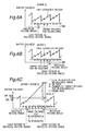
- FIG. 7 illustrates the process for extending the re-encoding range when the first extracted picture is S5 in Fig. 4.
- Fig. 7 (a) shows the re-encoding target pictures after step 2.
- Fig. 7 (b) shows the result of re-encoding with the target pictures selected in Fig. 7 (a).
- Fig. 7 (c) shows the re-encoding target pictures after step 10.
- Fig. 7 (d) shows the result of re-encoding with the target pictures selected in Fig. 7 (c).
- the target pictures are P4, B5, and B6, and the first picture in the recycled picture range is P7.
- the number of target pictures is increased in this case as shown in Fig. 7 (c).
- the first I-picture that is, picture I10 found searching forward from the first picture in the recycled picture range (referring to Fig. 7 (a), i.e., picture P7) is designated the last target picture in the re-encoding range.
- the target picture range is extended from pictures P4, B5, and B6 to include pictures P4, B5, B6, P7, B8, B9, and I10.
- pictures P4, B5, B6, P7, B8, B9, and I10 are re-encoded as pictures P4', I5', P6', P7', B8', B9', and P10'.
- the first picture in the recycled picture range is also updated to picture B11.
- the last I-picture in the range of re-encoding target pictures is changed to a P-picture, thereby reducing the code size of the picture.
- VBV_head By thus extending the re-encoding range and re-encoding I-picture I10 to a P-picture P10', VBV_head can be reduced. VBV_tail - VBV_head is thus increased, and the code allocation for each picture is thereby increased.
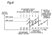
- Fig. 8 shows the change in buffer fullness before and after this process.
- the code size allocated to pictures I5', P6', and P4' is considered in Fig. 8. If VBV_head is the code size immediately before decoding picture P7 before extending the re-encoding range, VBV_head' is the code size at the corresponding time after extending the range. Note that VBV_head' is less than VBV_head.
- the code allocation for pictures I5', P6' and P4' is greater after this range extending process. This is because an I-picture, which consumes a large amount of code, is re-encoded as a P-picture, which uses less code compared with an I-picture.
- Fig. 9 illustrates the process for extending the re-encoding range when the last extracted picture is E5 in Fig. 5.
- Fig. 9 (a) shows the re-encoding target pictures after step 2.
- Fig. 9 (b) shows the result of re-encoding with the target pictures selected in Fig. 9 (a).
- Fig. 9 (c) shows the re-encoding target pictures after step 10.
- Fig. 9 (d) shows the result of re-encoding with the target pictures selected in Fig. 9 (c).
- the target picture in this case is B5, and the last picture in the recycled picture range is B3.
- picture B5 is re-encoded to P5' as shown in Fig. 9 (b). Furthermore, the original picture data is used for pictures B3 and before in the coding order. The order of the pictures in the coding order is up through B3, and then P5'.
- the first target picture in the re-encoding range is reset to the first I-picture (that is, picture I1) found searching backward from the last picture in the recycled picture range (referring to Fig. 9 (a), i.e., picture B3) using the stream structure data.
- the target picture range is extended from picture B5 to pictures I1, B2, B3, and B5.
- P-picture P4 is reproduced outside the extracted scene range, and is thus deleted.
- pictures I1, B2, B3, and B5 are re-encoded to pictures P1', B2', B3', and P5'.
- the last picture in the recycled picture range is also updated to the picture immediately before picture I1.
- VBV_tail can be increased.
- VBV_tail - VBV_head is thus increased, and the code allocation for each picture is thereby increased.
- Fig. 10 shows the change in buffer fullness before and after this process.
- the code size allocated to pictures P5' is considered in Fig. 10. If VBV_tail is the code size immediately before decoding the next picture after picture B3 before extending the re-encoding range, VBV_tail' is the code size at the corresponding time after extending the range. Note that VBV_tail' is greater than VBV_tail.
- the code allocation for picture P5' is greater after this range extending process. This is because an I-picture, which consumes a large amount of code, is re-encoded as a P-picture, which uses less code compared with an I-picture.
- VBV_tail - VBV_head can be increased by only increasing VBV_tail or only decreasing VBV_head, and that this is sufficient for some cases, but it is preferable to both increase VBV_tail and decrease VBV_head.
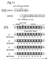
- re-encoding target picture importance calculating means 110 determines the importance of each target picture in the re-encoding range. This process is described more fully below with reference to Fig. 11.
- Fig. 11 shows the process for calculating target picture importance for scene 1 and scene 2 extracted from edit stream sources 1 and 2, respectively, and then combined to a new video stream.
- Step 2 identifies pictures B12 and B13 in scene 1, and pictures B2 to P7 in scene 2, as the target pictures at the edit point between scenes 1 and 2.
- Step 4 then specifies the picture type after re-encoding as indicated from picture P12' to P8'. This consecutive sequence of target pictures is the re-encoding range.
- the importance rating of each target picture in the re-encoding range is initially set uniformly to the same value.
- the picture importance rating is initially set at 50 as shown in Fig. 11 (a).
- the importance rating of each target picture is then increased or decreased based on the result of a verification process determining target picture importance. This verification process is described below.
- the re-encoding ranges are considered separately in each scene.
- a constant B multiplied by the number of target pictures in the re-encoding range starting with the second target picture is added to the importance rating of the first target picture, that is, the number of pictures in the re-encoding range minus 1.
- Fig. 11 (b) The beginning of scene 2 is I-picture 12'.
- Six target pictures follow picture I2'.
- Constant B in this exemplary embodiment is 1. Therefore (6 x 1) is added to the initial importance rating of picture I2', which is 50 now, and the importance of picture I2' is thus reset to 56. The importance of the first picture in a scene is thus increased.
- the second and subsequent target pictures are P-pictures or B-pictures at the beginning of a scene, and are encoded by referring to the first target picture, which is an I-picture. Therefore, if the quality of the first target picture is poor, the quality of target pictures following thereafter will be degraded, and a drop in picture quality will be propagated. In other words, the more target pictures there are following the first target picture, the more important the first target picture becomes.
- the importance rating of the last target pictures is decreased a constant C. This is shown in Fig. 11 (c). Note that constant C is also 1 in this preferred embodiment of the invention.
- the end of scene 1 is picture P13'. Its importance rating of 50 (the initial value) is therefore reduced 1 to obtain the new importance rating of 49 for picture P13' The importance of pictures at the end of a scene is thus reduced.
- Target picture importance is also adjusted up or down by comparing the code size of the target pictures before editing with the average code size of each picture based on the picture type of the target pictures before editing and the picture type after re-encoding.
- Equation (8) Dave uses the average code size value calculated for each picture type in step 9 that matches Dorg. Constant D in equation (8) is also 100 in this embodiment. The decimal part of the result of equation (8) is rounded to obtain importance adjustment dG. This is shown in Fig. 11 (d). The importance rating of each target picture is thus determined.
- the re-encoding target picture target code size calculating means 111 calculates the code allocation (target code size) for each target picture based on the importance of each target picture, the re-encoding range code allocation, the number of target pictures, and the picture type after re-encoding.
- the first step is to define the average code size calculated in step 8 as the initial value for the target code size.
- this target code size is adjusted based on the importance rating derived in step 11. This operation is further described below.
- the average importance of the target pictures contained in the re-encoding range is obtained.
- (target picture importance rating)/(average importance) is multiplied by the target code size for each picture to increase or decrease the target code size. Let us assume that the total target code size of each target picture at this point is T1.
- the difference between the re-encoding range code allocation and the target code size is distributed to each of the target pictures according to the ratio of the average code size of the pictures. Finally, it is verified that buffer underflow and buffer overflow will not occur at the target picture decoding timing; if either a buffer underflow or overflow will occur, the target code size of each target picture is adjusted again. This operation is further described below.
- Di_add Tdiff Ni + Np ⁇ Dp Di + Nb ⁇ Db Di
- equation 12 (a) defines the condition for a buffer overflow not occurring, and (b) the condition for a buffer underflow not occurring. If equation 12 (a) is false, buffer overflow will occur at the decode timing of the target picture being verified. In this case, the target code size of the target picture is recalculated using equation 13 (a), and the difference before and after the recalculation is distributed to the target pictures following thereafter according to the ratio of the average code size of each picture type obtained in step 9.
- the total code size of the re-encoded pictures thus becomes equal to the target total code size.
- the target code size for each target picture is thus determined.
- step 13 the picture re-encoding means 112 re-encodes the target pictures based on the calculated target picture code size and the picture type after re-encoding.
- the I-picture referenced for coding the first target picture is first found in the stream structure data, and is decoded.
- the re-encoder continues searching forward in the stream to decode the I-pictures, P-pictures, and target pictures for re-encoding.
- Future and past referenced pictures that is, pictures used for predictive coding P-pictures or B-pictures, are buffered to temporary storage at this time.
- a P-picture is decoded using the first I-picture or P-picture encountered in the stream as a "future referenced picture.”
- the picture is decoded and then re-encoded to match the target code size.
- the code size is adjusting by adding invalid data such as stuffing or padding bytes, or the difference between the target code size and the coded size of the target picture is added to the target code size of the next target picture.
- the picture type after re-encoding is a P-picture, the picture is buffered to memory for use as a future referenced picture. Processing ends when all target pictures have been re-encoded.
- step 14 the scene linking means 113 links the scenes to produce a new bitstream.
- the scene linking means 113 links the scenes in the specified sequence based on the scene information input in step 1, and generates a new stream of the output file name specified in the scene information. This operation is described more fully below with reference to Fig. 12.
- step 14 the scenes thus prepared are connected in the specified sequence as shown in Fig. 12 (b). This is accomplished as described below.
- the re-encoded target pictures at the beginning of scene 1 are connected in coding order. If the picture type of the target picture before editing is different from the picture type after re-encoding, the pictures are rearranged based on the display order in a coding order conforming to the picture type after target picture re-encoding.
- the re-encoded target pictures at the beginning of the scene are connected to the recycled picture range of scene 1.
- the re-encoded target pictures at the end of scene 1 are then connected in coding order.
- the editing process of the present invention described above thus extracts a plurality of consecutive frames (scenes) from a bitstream for editing, and produces a new stream of plural linked scenes.
- scenes can be selected from a single bitstream, scenes can contain overlapping frame sequences, and the scenes can be selected from a plurality of different bitstreams.
- the editing process of the encoded stream is accomplished by means of a software program in the above described exemplary embodiment of the invention, but it will be obvious to one with ordinary skill in the related art that part or all of this process can also be achieved using logic circuits or other hardware components. Thus comprising the invention makes it possible to shorten the processing time.
- the present invention also includes a data storage medium to which the steps or a data stream expressing the steps shown in Fig. 3 are recorded.
- the invention as described above extracts a plurality of consecutive frames (scene) from an existing MPEG stream, reconnects a plurality of scenes, and produces a new stream that will not cause a buffer underflow or buffer overflow.
- buffer control processing is limited to the least required processing and is not dependent on the scene length. Data processing and the processing load are therefore not great, and it is not necessary to insert compensating P-pictures.
- the frame count before and after editing are thus the same, and editing can be easily accomplished.
- the re-encoding target picture type determining means of the present invention extensively uses picture types with a code size smaller than I-pictures, allocates efficiently, and suppresses picture quality deterioration.
- the code allocation verifying means and re-encoding range expanding means of the present invention extend the range of re-encoded frames when necessary, verify that the allocated code is always within an appropriate range, and thus maintain the overall quality of the video.
- the re-encoding range expanding means of the invention increases the code allocation to other pictures, and thus achieves even better picture quality.
- the re-encoding target picture importance calculating means assures that more code is allocated to pictures with a high importance rating, less is allocated to pictures of lesser importance, and thus assures efficient code allocation. This further prevents propagating picture quality loss at the edit point, and thus maintains the overall quality of the video.
- the buffer fullness analyzing means of the present invention verifies the change in buffer fullness at the edit point when editing a VBR stream, and thus prevents buffer underflow.
Landscapes
- Engineering & Computer Science (AREA)
- Multimedia (AREA)
- Signal Processing (AREA)
- Compression Or Coding Systems Of Tv Signals (AREA)
- Television Signal Processing For Recording (AREA)
Applications Claiming Priority (2)
| Application Number | Priority Date | Filing Date | Title |
|---|---|---|---|
| JP31211499 | 1999-11-02 | ||
| JP31211499 | 1999-11-02 |
Publications (2)
| Publication Number | Publication Date |
|---|---|
| EP1098526A2 true EP1098526A2 (fr) | 2001-05-09 |
| EP1098526A3 EP1098526A3 (fr) | 2004-09-15 |
Family
ID=18025420
Family Applications (1)
| Application Number | Title | Priority Date | Filing Date |
|---|---|---|---|
| EP00123772A Withdrawn EP1098526A3 (fr) | 1999-11-02 | 2000-11-01 | Méthode et dispositif d'édition vidéo |
Country Status (2)
| Country | Link |
|---|---|
| US (1) | US6587506B1 (fr) |
| EP (1) | EP1098526A3 (fr) |
Cited By (3)
| Publication number | Priority date | Publication date | Assignee | Title |
|---|---|---|---|---|
| EP1503592A1 (fr) * | 2003-07-30 | 2005-02-02 | Sony Corporation | Appareil d'édition, méthode de contrôle de débit, et programme de contrôle de débit |
| WO2005122585A1 (fr) * | 2004-06-14 | 2005-12-22 | Matsushita Electric Industrial Co., Ltd. | Procede et appareil de mise en forme de flots de donnees |
| EP1811784A4 (fr) * | 2004-10-13 | 2010-08-04 | Sharp Kk | Re-codeur d'image animee, editeur, programme d'image animee et support d'enregistrement |
Families Citing this family (46)
| Publication number | Priority date | Publication date | Assignee | Title |
|---|---|---|---|---|
| US6731684B1 (en) * | 1998-09-29 | 2004-05-04 | General Instrument Corporation | Method and apparatus for detecting scene changes and adjusting picture coding type in a high definition television encoder |
| JP2002152759A (ja) * | 2000-11-10 | 2002-05-24 | Sony Corp | 画像情報変換装置および画像情報変換方法 |
| US7006511B2 (en) * | 2001-07-17 | 2006-02-28 | Avaya Technology Corp. | Dynamic jitter buffering for voice-over-IP and other packet-based communication systems |
| JP4135395B2 (ja) * | 2002-04-26 | 2008-08-20 | 日本電気株式会社 | 符号化パケット伝送受信方法およびその装置ならびにプログラム |
| US7418037B1 (en) * | 2002-07-15 | 2008-08-26 | Apple Inc. | Method of performing rate control for a compression system |
| US7804897B1 (en) * | 2002-12-16 | 2010-09-28 | Apple Inc. | Method for implementing an improved quantizer in a multimedia compression and encoding system |
| US7940843B1 (en) | 2002-12-16 | 2011-05-10 | Apple Inc. | Method of implementing improved rate control for a multimedia compression and encoding system |
| TW591952B (en) * | 2003-03-14 | 2004-06-11 | Cyberlink Corp | Intelligent video stream processing method and system thereof |
| US7266147B2 (en) * | 2003-03-31 | 2007-09-04 | Sharp Laboratories Of America, Inc. | Hypothetical reference decoder |
| US8175154B2 (en) * | 2003-06-03 | 2012-05-08 | General Instrument Corporation | Method for restructuring a group of pictures to provide for random access into the group of pictures |
| US7672864B2 (en) * | 2004-01-09 | 2010-03-02 | Ricoh Company Ltd. | Generating and displaying level-of-interest values |
| US8401069B2 (en) * | 2004-04-05 | 2013-03-19 | Snell Limited | Apparatus and process for re-timing video cuts |
| KR101194967B1 (ko) * | 2004-08-25 | 2012-10-25 | 소니 주식회사 | 정보 처리 장치 및 정보 처리 방법, 및 기록 매체 |
| US8437392B2 (en) * | 2005-04-15 | 2013-05-07 | Apple Inc. | Selective reencoding for GOP conformity |
| JP4492484B2 (ja) * | 2005-08-22 | 2010-06-30 | ソニー株式会社 | 情報処理装置および情報処理方法、記録媒体、並びに、プログラム |
| US7515710B2 (en) | 2006-03-14 | 2009-04-07 | Divx, Inc. | Federated digital rights management scheme including trusted systems |
| US8416859B2 (en) | 2006-11-13 | 2013-04-09 | Cisco Technology, Inc. | Signalling and extraction in compressed video of pictures belonging to interdependency tiers |
| US8875199B2 (en) | 2006-11-13 | 2014-10-28 | Cisco Technology, Inc. | Indicating picture usefulness for playback optimization |
| US20090180546A1 (en) | 2008-01-09 | 2009-07-16 | Rodriguez Arturo A | Assistance for processing pictures in concatenated video streams |
| US8804845B2 (en) | 2007-07-31 | 2014-08-12 | Cisco Technology, Inc. | Non-enhancing media redundancy coding for mitigating transmission impairments |
| US8958486B2 (en) | 2007-07-31 | 2015-02-17 | Cisco Technology, Inc. | Simultaneous processing of media and redundancy streams for mitigating impairments |
| US8718388B2 (en) | 2007-12-11 | 2014-05-06 | Cisco Technology, Inc. | Video processing with tiered interdependencies of pictures |
| US8416858B2 (en) | 2008-02-29 | 2013-04-09 | Cisco Technology, Inc. | Signalling picture encoding schemes and associated picture properties |
| US8923385B2 (en) * | 2008-05-01 | 2014-12-30 | Nvidia Corporation | Rewind-enabled hardware encoder |
| WO2009152450A1 (fr) | 2008-06-12 | 2009-12-17 | Cisco Technology, Inc. | Signaux d’interdépendances d’images dans le contexte du mmco pour aider à manipuler un flux |
| US8971402B2 (en) * | 2008-06-17 | 2015-03-03 | Cisco Technology, Inc. | Processing of impaired and incomplete multi-latticed video streams |
| US8699578B2 (en) | 2008-06-17 | 2014-04-15 | Cisco Technology, Inc. | Methods and systems for processing multi-latticed video streams |
| US8705631B2 (en) | 2008-06-17 | 2014-04-22 | Cisco Technology, Inc. | Time-shifted transport of multi-latticed video for resiliency from burst-error effects |
| US9407925B2 (en) * | 2008-10-30 | 2016-08-02 | Vixs Systems, Inc. | Video transcoding system with quality readjustment based on high scene cost detection and method for use therewith |
| US8259817B2 (en) * | 2008-11-12 | 2012-09-04 | Cisco Technology, Inc. | Facilitating fast channel changes through promotion of pictures |
| US8782261B1 (en) | 2009-04-03 | 2014-07-15 | Cisco Technology, Inc. | System and method for authorization of segment boundary notifications |
| US8949883B2 (en) | 2009-05-12 | 2015-02-03 | Cisco Technology, Inc. | Signalling buffer characteristics for splicing operations of video streams |
| US8279926B2 (en) | 2009-06-18 | 2012-10-02 | Cisco Technology, Inc. | Dynamic streaming with latticed representations of video |
| US20110222837A1 (en) * | 2010-03-11 | 2011-09-15 | Cisco Technology, Inc. | Management of picture referencing in video streams for plural playback modes |
| US9131236B2 (en) | 2010-05-12 | 2015-09-08 | Nippon Telegraph And Telephone Corporation | Code amount control method and apparatus |
| US8914534B2 (en) | 2011-01-05 | 2014-12-16 | Sonic Ip, Inc. | Systems and methods for adaptive bitrate streaming of media stored in matroska container files using hypertext transfer protocol |
| US9467708B2 (en) | 2011-08-30 | 2016-10-11 | Sonic Ip, Inc. | Selection of resolutions for seamless resolution switching of multimedia content |
| US8909922B2 (en) | 2011-09-01 | 2014-12-09 | Sonic Ip, Inc. | Systems and methods for playing back alternative streams of protected content protected using common cryptographic information |
| TWI488502B (zh) * | 2012-12-06 | 2015-06-11 | Acer Inc | 視訊編修方法與視訊編修裝置 |
| CN103888781B (zh) * | 2012-12-21 | 2017-04-12 | 宏碁股份有限公司 | 视频编修方法与视频编修装置 |
| US9313510B2 (en) | 2012-12-31 | 2016-04-12 | Sonic Ip, Inc. | Use of objective quality measures of streamed content to reduce streaming bandwidth |
| US9191457B2 (en) | 2012-12-31 | 2015-11-17 | Sonic Ip, Inc. | Systems, methods, and media for controlling delivery of content |
| US9906785B2 (en) * | 2013-03-15 | 2018-02-27 | Sonic Ip, Inc. | Systems, methods, and media for transcoding video data according to encoding parameters indicated by received metadata |
| US9094737B2 (en) | 2013-05-30 | 2015-07-28 | Sonic Ip, Inc. | Network video streaming with trick play based on separate trick play files |
| KR20150128151A (ko) * | 2014-05-08 | 2015-11-18 | 삼성전자주식회사 | 비디오 스트리밍 방법 및 이를 지원하는 전자 장치 |
| US10880585B1 (en) * | 2019-06-12 | 2020-12-29 | Amazon Technologies, Inc. | Split-and-stitch media content encoding |
Family Cites Families (13)
| Publication number | Priority date | Publication date | Assignee | Title |
|---|---|---|---|---|
| JPH07212766A (ja) * | 1994-01-18 | 1995-08-11 | Matsushita Electric Ind Co Ltd | 動画像圧縮データ切り換え装置 |
| JPH08149408A (ja) | 1994-11-17 | 1996-06-07 | Matsushita Electric Ind Co Ltd | ディジタル動画編集方法及び装置 |
| JP3427505B2 (ja) | 1994-08-25 | 2003-07-22 | 松下電器産業株式会社 | 画像符号化方法と編集装置 |
| US5623424A (en) * | 1995-05-08 | 1997-04-22 | Kabushiki Kaisha Toshiba | Rate-controlled digital video editing method and system which controls bit allocation of a video encoder by varying quantization levels |
| US5764293A (en) * | 1995-12-26 | 1998-06-09 | C-Cube Microsystems, Inc. | Method of encoding video using master and slave encoders wherein bit budgets for frames to be encoded are based on encoded frames |
| JPH1013783A (ja) | 1996-06-21 | 1998-01-16 | Toshiba Corp | 圧縮画像データのインサート編集方式 |
| JP3325464B2 (ja) | 1996-07-18 | 2002-09-17 | 沖電気工業株式会社 | 動画像処理装置 |
| JPH10164592A (ja) | 1996-12-04 | 1998-06-19 | Matsushita Electric Ind Co Ltd | 圧縮動画像の符号化方法 |
| JPH10285529A (ja) | 1997-04-04 | 1998-10-23 | Sony Corp | 画像編集装置および画像編集方法 |
| US6049569A (en) * | 1997-12-09 | 2000-04-11 | Philips Electronics N.A. Corporation | Method and apparatus for encoding digital video bit streams with seamless splice points and method and apparatus for splicing such digital video bit streams |
| EP0935395A2 (fr) * | 1998-02-06 | 1999-08-11 | Sony Corporation | Appareil et méthode de codage vidéo |
| GB9807202D0 (en) * | 1998-04-03 | 1998-06-03 | Nds Ltd | A method and apparatus for processing compressed video data streams |
| JPH11341435A (ja) * | 1998-05-22 | 1999-12-10 | Sony Corp | 編集方法および編集装置 |
-
2000
- 2000-11-01 US US09/702,806 patent/US6587506B1/en not_active Expired - Lifetime
- 2000-11-01 EP EP00123772A patent/EP1098526A3/fr not_active Withdrawn
Cited By (4)
| Publication number | Priority date | Publication date | Assignee | Title |
|---|---|---|---|---|
| EP1503592A1 (fr) * | 2003-07-30 | 2005-02-02 | Sony Corporation | Appareil d'édition, méthode de contrôle de débit, et programme de contrôle de débit |
| WO2005122585A1 (fr) * | 2004-06-14 | 2005-12-22 | Matsushita Electric Industrial Co., Ltd. | Procede et appareil de mise en forme de flots de donnees |
| CN1713727B (zh) * | 2004-06-14 | 2010-11-10 | 松下电器产业株式会社 | 编辑资料流的方法及装置 |
| EP1811784A4 (fr) * | 2004-10-13 | 2010-08-04 | Sharp Kk | Re-codeur d'image animee, editeur, programme d'image animee et support d'enregistrement |
Also Published As
| Publication number | Publication date |
|---|---|
| US6587506B1 (en) | 2003-07-01 |
| EP1098526A3 (fr) | 2004-09-15 |
Similar Documents
| Publication | Publication Date | Title |
|---|---|---|
| US6587506B1 (en) | Video editing apparatus, video editing method, and data storage medium for a video editing program | |
| US6396875B1 (en) | Method of switching of coded video sequences and corresponding device | |
| US6724977B1 (en) | Compressed video editor with transition buffer matcher | |
| KR100729541B1 (ko) | 부호화 히스토리 정보를 이용하는 트랜스코딩 시스템 | |
| KR100538135B1 (ko) | 정보 스트림 프레임 동기 방법 및 장치 | |
| JP4275746B2 (ja) | 符号化ビデオシーケンスの切り替え方法及びこれに対応する装置 | |
| US6674796B1 (en) | Statistical multiplexed video encoding for diverse video formats | |
| US6819714B2 (en) | Video encoding apparatus that adjusts code amount by skipping encoding of image data | |
| JP4402219B2 (ja) | ビデオ・データ中のフラッシュ・フレームの検出および符号化 | |
| US20020064177A1 (en) | Method and apparatus for forming and utilizing a slotted mpeg transport stream | |
| US20100166081A1 (en) | Video stream processing apparatus and control method, program and recording medium for the same | |
| KR100334364B1 (ko) | 온-스크린 디스플레이 스크롤 장치 | |
| US6549578B1 (en) | Moving picture synthesizing device | |
| JP2001326940A (ja) | 符号化動画像ビットストリーム処理方法、及び装置、並びに符号化動画像ビットストリーム処理プログラムを格納した記録媒体 | |
| KR20070084128A (ko) | 중간 형식으로 변환하는 2단계 산술 복호 | |
| US20080159636A1 (en) | Encoding apparatus and encoding method | |
| US7173969B2 (en) | Moving picture coding apparatus | |
| US8904426B2 (en) | Preconditioning ad content for digital program insertion | |
| US20020015577A1 (en) | Data distribution apparatus and method, and data distribution system | |
| US6539054B1 (en) | Image output apparatus, image reproduction method, object composition apparatus, object composition method, and data storage medium | |
| US6798835B2 (en) | Apparatus and method of switching moving-picture bitstream | |
| EP1638335B1 (fr) | Dispositif et procede de traitement d'image et support et programme d'enregistrement | |
| JP2001197504A (ja) | 映像編集装置、映像編集方法及びそのプログラムを記録した記録媒体 | |
| JPH08289297A (ja) | 音声付き動画データ作成装置 | |
| JP2002218458A (ja) | 映像再生装置 |
Legal Events
| Date | Code | Title | Description |
|---|---|---|---|
| PUAI | Public reference made under article 153(3) epc to a published international application that has entered the european phase |
Free format text: ORIGINAL CODE: 0009012 |
|
| AK | Designated contracting states |
Kind code of ref document: A2 Designated state(s): AT BE CH CY DE DK ES FI FR GB GR IE IT LI LU MC NL PT SE TR |
|
| AX | Request for extension of the european patent |
Free format text: AL;LT;LV;MK;RO;SI |
|
| PUAL | Search report despatched |
Free format text: ORIGINAL CODE: 0009013 |
|
| AK | Designated contracting states |
Kind code of ref document: A3 Designated state(s): AT BE CH CY DE DK ES FI FR GB GR IE IT LI LU MC NL PT SE TR |
|
| AX | Request for extension of the european patent |
Extension state: AL LT LV MK RO SI |
|
| AKX | Designation fees paid | ||
| REG | Reference to a national code |
Ref country code: DE Ref legal event code: 8566 |
|
| STAA | Information on the status of an ep patent application or granted ep patent |
Free format text: STATUS: THE APPLICATION IS DEEMED TO BE WITHDRAWN |
|
| 18D | Application deemed to be withdrawn |
Effective date: 20050316 |