EP1099376A2 - Fischkäfig hoher Dichte - Google Patents
Fischkäfig hoher Dichte Download PDFInfo
- Publication number
- EP1099376A2 EP1099376A2 EP00124114A EP00124114A EP1099376A2 EP 1099376 A2 EP1099376 A2 EP 1099376A2 EP 00124114 A EP00124114 A EP 00124114A EP 00124114 A EP00124114 A EP 00124114A EP 1099376 A2 EP1099376 A2 EP 1099376A2
- Authority
- EP
- European Patent Office
- Prior art keywords
- water
- tank
- rack
- tanks
- drain
- Prior art date
- Legal status (The legal status is an assumption and is not a legal conclusion. Google has not performed a legal analysis and makes no representation as to the accuracy of the status listed.)
- Granted
Links
- 241001465754 Metazoa Species 0.000 title abstract description 37
- XLYOFNOQVPJJNP-UHFFFAOYSA-N water Substances O XLYOFNOQVPJJNP-UHFFFAOYSA-N 0.000 claims abstract description 234
- 239000013049 sediment Substances 0.000 claims abstract description 9
- 239000002351 wastewater Substances 0.000 claims description 29
- 230000008878 coupling Effects 0.000 claims description 17
- 238000010168 coupling process Methods 0.000 claims description 17
- 238000005859 coupling reaction Methods 0.000 claims description 17
- 238000009833 condensation Methods 0.000 claims description 9
- 238000004891 communication Methods 0.000 claims description 6
- 230000005484 gravity Effects 0.000 claims description 6
- 239000012530 fluid Substances 0.000 claims description 5
- 239000000725 suspension Substances 0.000 claims description 5
- 230000005494 condensation Effects 0.000 claims description 4
- 238000002347 injection Methods 0.000 claims description 4
- 239000007924 injection Substances 0.000 claims description 4
- 230000003134 recirculating effect Effects 0.000 claims description 4
- 229920003023 plastic Polymers 0.000 claims description 3
- 239000004417 polycarbonate Substances 0.000 claims description 3
- 229920000515 polycarbonate Polymers 0.000 claims description 3
- 239000004033 plastic Substances 0.000 claims description 2
- 239000002991 molded plastic Substances 0.000 claims 2
- 239000003610 charcoal Substances 0.000 claims 1
- 238000007599 discharging Methods 0.000 claims 1
- 239000012528 membrane Substances 0.000 claims 1
- 239000004576 sand Substances 0.000 claims 1
- 241000252212 Danio rerio Species 0.000 abstract description 4
- 238000001125 extrusion Methods 0.000 abstract description 4
- 239000003570 air Substances 0.000 description 61
- 241000251468 Actinopterygii Species 0.000 description 18
- 238000007789 sealing Methods 0.000 description 10
- 239000008400 supply water Substances 0.000 description 9
- 238000001914 filtration Methods 0.000 description 7
- 201000010099 disease Diseases 0.000 description 6
- 208000037265 diseases, disorders, signs and symptoms Diseases 0.000 description 6
- 230000002093 peripheral effect Effects 0.000 description 6
- 238000005273 aeration Methods 0.000 description 5
- 230000005587 bubbling Effects 0.000 description 5
- 239000000463 material Substances 0.000 description 5
- 238000010171 animal model Methods 0.000 description 4
- 238000009395 breeding Methods 0.000 description 4
- 230000001488 breeding effect Effects 0.000 description 4
- 210000005069 ears Anatomy 0.000 description 4
- 239000013505 freshwater Substances 0.000 description 4
- 238000012360 testing method Methods 0.000 description 4
- 241000699670 Mus sp. Species 0.000 description 3
- 238000004140 cleaning Methods 0.000 description 3
- 239000000428 dust Substances 0.000 description 3
- 230000000694 effects Effects 0.000 description 3
- 238000002474 experimental method Methods 0.000 description 3
- 238000009434 installation Methods 0.000 description 3
- 238000012423 maintenance Methods 0.000 description 3
- 238000006213 oxygenation reaction Methods 0.000 description 3
- 244000052769 pathogen Species 0.000 description 3
- OKTJSMMVPCPJKN-UHFFFAOYSA-N Carbon Chemical compound [C] OKTJSMMVPCPJKN-UHFFFAOYSA-N 0.000 description 2
- 241000124008 Mammalia Species 0.000 description 2
- 230000009471 action Effects 0.000 description 2
- 239000000853 adhesive Substances 0.000 description 2
- 230000001070 adhesive effect Effects 0.000 description 2
- 230000004888 barrier function Effects 0.000 description 2
- 230000003115 biocidal effect Effects 0.000 description 2
- 239000003651 drinking water Substances 0.000 description 2
- 235000020188 drinking water Nutrition 0.000 description 2
- 230000002068 genetic effect Effects 0.000 description 2
- 238000009533 lab test Methods 0.000 description 2
- 239000002184 metal Substances 0.000 description 2
- 238000000746 purification Methods 0.000 description 2
- 239000008213 purified water Substances 0.000 description 2
- 230000000284 resting effect Effects 0.000 description 2
- 239000007787 solid Substances 0.000 description 2
- 239000011800 void material Substances 0.000 description 2
- 238000003466 welding Methods 0.000 description 2
- 206010013082 Discomfort Diseases 0.000 description 1
- 241000283973 Oryctolagus cuniculus Species 0.000 description 1
- 241000700159 Rattus Species 0.000 description 1
- 208000034817 Waterborne disease Diseases 0.000 description 1
- 238000005276 aerator Methods 0.000 description 1
- 244000000022 airborne pathogen Species 0.000 description 1
- 230000002353 algacidal effect Effects 0.000 description 1
- 239000013566 allergen Substances 0.000 description 1
- OFCNXPDARWKPPY-UHFFFAOYSA-N allopurinol Chemical compound OC1=NC=NC2=C1C=NN2 OFCNXPDARWKPPY-UHFFFAOYSA-N 0.000 description 1
- 239000012080 ambient air Substances 0.000 description 1
- 238000009360 aquaculture Methods 0.000 description 1
- 244000144974 aquaculture Species 0.000 description 1
- 230000000712 assembly Effects 0.000 description 1
- 238000000429 assembly Methods 0.000 description 1
- 230000000903 blocking effect Effects 0.000 description 1
- 230000000295 complement effect Effects 0.000 description 1
- 230000001143 conditioned effect Effects 0.000 description 1
- 230000002498 deadly effect Effects 0.000 description 1
- 238000013461 design Methods 0.000 description 1
- 238000010586 diagram Methods 0.000 description 1
- 239000006185 dispersion Substances 0.000 description 1
- 238000006073 displacement reaction Methods 0.000 description 1
- 230000009977 dual effect Effects 0.000 description 1
- -1 e.g. Substances 0.000 description 1
- 239000013536 elastomeric material Substances 0.000 description 1
- 230000036541 health Effects 0.000 description 1
- 238000003780 insertion Methods 0.000 description 1
- 230000037431 insertion Effects 0.000 description 1
- 239000011159 matrix material Substances 0.000 description 1
- 229910021645 metal ion Inorganic materials 0.000 description 1
- 238000000034 method Methods 0.000 description 1
- 238000002156 mixing Methods 0.000 description 1
- 230000009972 noncorrosive effect Effects 0.000 description 1
- 235000019645 odor Nutrition 0.000 description 1
- 239000003921 oil Substances 0.000 description 1
- 244000045947 parasite Species 0.000 description 1
- 239000002245 particle Substances 0.000 description 1
- 230000037361 pathway Effects 0.000 description 1
- 238000009428 plumbing Methods 0.000 description 1
- 229920000642 polymer Polymers 0.000 description 1
- 239000010453 quartz Substances 0.000 description 1
- VYPSYNLAJGMNEJ-UHFFFAOYSA-N silicon dioxide Inorganic materials O=[Si]=O VYPSYNLAJGMNEJ-UHFFFAOYSA-N 0.000 description 1
- 125000006850 spacer group Chemical group 0.000 description 1
- 241000894007 species Species 0.000 description 1
- 230000000087 stabilizing effect Effects 0.000 description 1
- 231100000331 toxic Toxicity 0.000 description 1
- 230000002588 toxic effect Effects 0.000 description 1
- 238000012546 transfer Methods 0.000 description 1
- 230000007704 transition Effects 0.000 description 1
- 239000002699 waste material Substances 0.000 description 1
Images





Classifications
-
- A—HUMAN NECESSITIES
- A01—AGRICULTURE; FORESTRY; ANIMAL HUSBANDRY; HUNTING; TRAPPING; FISHING
- A01K—ANIMAL HUSBANDRY; AVICULTURE; APICULTURE; PISCICULTURE; FISHING; REARING OR BREEDING ANIMALS, NOT OTHERWISE PROVIDED FOR; NEW BREEDS OF ANIMALS
- A01K63/00—Receptacles for live fish, e.g. aquaria; Terraria
- A01K63/003—Aquaria; Terraria
-
- A—HUMAN NECESSITIES
- A01—AGRICULTURE; FORESTRY; ANIMAL HUSBANDRY; HUNTING; TRAPPING; FISHING
- A01K—ANIMAL HUSBANDRY; AVICULTURE; APICULTURE; PISCICULTURE; FISHING; REARING OR BREEDING ANIMALS, NOT OTHERWISE PROVIDED FOR; NEW BREEDS OF ANIMALS
- A01K1/00—Housing animals; Equipment therefor
- A01K1/02—Pigsties; Dog-kennels; Rabbit-hutches or the like
- A01K1/03—Housing for domestic or laboratory animals
- A01K1/031—Cages for laboratory animals; Cages for measuring metabolism of animals
Definitions
- the invention relates to animal housing systems, and more particularly provides a housing system for aquatic animals wherein covered tanks or aquaria are removably carried in tiers on a shelf-like rack. Insertion of a tank into the rack couples the tank to a circulating water supply and preferably also to a supply of compressed air for aeration of the water. Removal of a tank from the rack decouples that tank from the circulating supply, also removing the tank as an interruption of the circulation whereby circulation continues.
- the housing system is especially useful as a high density laboratory facility for Danio Reria (zebrafish) used in medical and genetic testing and the like, or being bred for such use, and also is applicable to pet stores, tropical fish hobbyists and the like.
- an optimal housing arrangement should be compact, namely the density of the animal population should be high. It should be neat and clean. It should be readily capable of occupying the same floor space as the humans that are providing services and/or conducting testing.
- the maintenance and use of the system should maximize comfort and minimize danger for both the animals and the humans, for example not only preventing potential catastrophe such as the transfer of a deadly disease, but also avoiding simple discomforts such as unpleasant odors or dispersion of allergens.
- Some animals used in laboratory experiments can represent a substantial investment. Rare pets are expensive to acquire, as are certain laboratory animals such as those having specific genetic characteristics or propensities that are useful for testing. Apart from the cost of the animals, the time and effort invested to carry on an experiment makes it important that most or all of the animals survive for the duration of the experiment. It is important that the animals stay healthy while housed and also that their management and upkeep be as convenient as practicable.
- high density housing for mammals such as mice are disclosed, for example in US-A 32,113 - Harr (Air conditioned laboratory rack for animal cages); US-A 4,690,100 - Thomas (Ventilated animal housing and service system with cage filter covers); US-A 5,044,316 - Thomas (Ventilated animal caging system with cage racks and filter covers including valves operable by rack); US-A 5,474,024 - Thomas (Caging system with slide bar operator for quick disconnect water fitting), and others.
- the disclosures of these patents are incorporated for their teachings regarding high density housing and protection from disease while supplying animals with the necessities of life.
- US-A 5,513,596 discloses a quick disconnect water supply assembly for removably coupling cages to a drinking water supply.
- a conduit is mounted to pass through the barrier defined by a wall of the cage box, and contains an occupant-operated valve.
- the water supply assembly couples into a water supply line when the cage is inserted into the rack.
- a linking member attaches to the water line for opening or closing the connection with the water line and a manually movable knob is operated to engage or disengage the cage with the water supply. The connection closes off the water supply when the cage is withdrawn from the cage rack system.
- the drinking water supply as described is substantially a one way affair, namely with water flowing from the supply into the cage enclosure without a flow return.
- US-A 5,174,239 discloses an aquarium device that is sealed and coupled to water fed under pressure into the aquarium body by a feed pump.
- the water pressure resulting from the pump causes used water in the aquarium body to be discharged through a drain pipe.
- the drain pipe is coupled to a filtration and aeration unit that leads into the feed pump, providing a closed circulation path including the aquarium volume and the filter/aerator in a closed loop.
- a closed loop filtration device for each aquarium is the normal filtration arrangement in a multiple-aquarium installation. Although many aquarium tanks may be disposed in relative proximity, each one has its own separate water pump and water filter, which arrangement avoids a sharing of water that might engender the spread of disease.
- Aeration supplies on the other hand are typically commonly coupled to flow lines leading into a number of tanks. No return is needed because the air discharge is by bubbling into the ambient air.
- US-A 5,042,425 discloses an aquarium and bird and animal containment system.
- the containment system includes racks for displaying one or more aquariums and racks for displaying bird and animal cages.
- a cabinet disposed between the aquarium support and the bird and animal support contains a sink, a water supply bringing water to the tanks and cages, and an air supply and distribution system bringing air to biological filters located in the aquarium tanks.
- An drain system carries away overflow water.
- US-A 5,197,409 discloses an aquatic tank display system suitable for use in a pet store or aquarium.
- the system includes a tank support frame having multiple tiers or levels for supporting tanks at different elevations. Portions of the frame are made of a non-corrosive material, because it is possible that areas around the tanks may get wet, and are non-conductive for avoiding electrical hazard.
- Each tank has an open top which is covered by a lamp fixture and a hinged lid.
- US-A 5,413,070 discloses a multiple tank display for a pet store or the like, comprising supports defining vertically spaced tiers.
- the tanks have transparent walls and those in the top and bottom tiers have front walls that are inclined to refract light and enhance viewing by a person standing in front of the display.
- US-A 5,365,886 discloses an aquarium containment system.
- Racks support multiple stacked sets of tanks and each rack has a removable lighting system.
- An automatic water distribution system is provided for the aquariums, including mechanical and biological filters and heaters. Sliding access panels facilitate access to the tops of the tanks for maintenance and cleaning purposes.
- a problem encountered when using circulating water to supply aerated and/or filtered water to multiple tanks is that the water for all the tanks can be contaminated by pathogens originating in one of the tanks. As a result, a circulating water system may be disadvantageous. On the other hand, having a single filtration and distribution system serving a number of tanks has obvious conveniences and cost savings.
- a disease problem of a similar type is encountered with mammal cage systems in that airborne dander from one cage can spread pathogens to other cages. Uncovered cages can release dust and dander on small particles that move about with eddy currents in the exhaust ducts when the cages are in the rack and elsewhere when the cages are out of the rack.
- Leakage and inadvertent water discharge can be a problem in water tank housing. Apart from spillage, temperature and humidity constraints can make the air around a tank system uncomfortable for humans. Different types of fish require water at different temperatures. For zebrafish, the water should be maintained at a temperature of about 85°F for optimum health and breeding conditions (specifically 25 to 31°C or 77 to 87.8°F). This is higher than room temperature, leading to high humidity levels, condensation of water on relatively cooler surfaces, and dripping water that may damage components of the housing, spread disease and create unpleasant working conditions for the humans that are involved.
- such housing is characterized by high animal density, that is, both housing a large number of fish or other aquatic animals in a relatively small volume of well serviced water, and also supporting the tanks or similar enclosures that hold the water in a very compact and space saving arrangement.
- a high density housing system for aquatic animals uses a number of individual tanks or aquaria that are suspended at a tilt angle by structural members of a rack (claim 15).
- these structural members comprise lateral support beams carried on longitudinal support rods that are in turn supported, for example, by panels at the opposite ends of the rack structure.
- Flanges are provided around the open tops of the tanks, which tank flanges are supported by complementary flanges of the lateral support beams of the rack.
- the flanges of the support beams are inclined downwardly and inwardly relative to the rack, thus tilting the supported tanks inwardly.
- Each tank is provided with a bottom structure that has inner walls having sloping sides leading to a low point at which sediment is collected for discharge with drained water.
- the bottoms of the tanks can form troughs parallel to the flanges and parallel to the lateral support beams.
- the troughs lead to a lowest point at the inward end of the trough, due to the inward sloping support of the tanks and the bottom trough.
- Other arrangements are also possible, characterized by the gradient around the bottom of the tank leading to a low point from which water is drained.
- a modified recirculating parallel-flow water system continuously supplies filtered water to all of the tanks (claim 12).
- the tanks are removably coupled in a parallel flow arrangement between common supply and drain conduits in which supply and drain water flow serially.
- each tank intercepts one of a number of parallel flow paths provided at spaced positions, one position per tank, between the common supply conduit and the common drain conduit.
- purified supply water flows into the tank from the supply conduit, and used tank water is extracted and drained from said lowest point along the bottom of the tank, from which the water flows into the drain (claim 1).
- the flow from the supply water conduit to the drain conduit is not intercepted at the respective tank position, and flows directly from the source to the drain.
- the water flows in a completely closed circuit, passing a filtration and purification system and passing through those tanks that are inserted to intercept flow of water from the source conduit to the drain conduit at each of those tanks' positions.
- the water supply and water return conduits or lines can be formed integrally with or rigidly attached to the rack to provide structural support for the lateral beams.
- the water supply lines are preferably formed integrally with multiple lumen extrusions in which the parallel flows at the tank positions are between a supply lumen and a drain lumen.
- a third lumen is coupled to the tank by a spring biased ball valve supplying air to bubble through and aerate the water in each aquarium when the tank is inserted, said ball valve being closed when the tank is removed from the rack.
- water supply, water drain and air supply conduits are integrated into an aquarium supporting rack, for supply and removal of water to covered aquarium tanks, and for supply of air for aerating the water.
- the tanks and conduits are structured such that each tank engages with the conduits by intersecting water flow paths running in parallel, and by a valved connection to a serial air supply, such connections being made only when an aquarium is in a supported position on the rack.
- detachment of any or all of the tanks does not interfere with the re-circulating water system, which continues to flow in a closed loop.
- the water drained from the tank flows from a lowermost point at the lower end of the tank (which tilts inwardly due to the tilting flanges of the lateral support beams) into a central longitudinal drain path provided at each level or tier.
- the applicable drain conduit is a drain part of the multiple lumen extrusion, which is at the higher side of the tilting tanks in the respective tier, spaced laterally outward from the longitudinal center.
- the filtration and purification portion of the circulating water system preferably include filtering of solids (e.g., with a diatomaceous element), removal of oils and volatile components (e.g., with an activated charcoal element) and a biocidal/algaecidal element (e.g., an ultraviolet lamp incident on a quartz tube section along the water flowpath, to destroy any living tissue).
- filtering of solids e.g., with a diatomaceous element
- removal of oils and volatile components e.g., with an activated charcoal element
- a biocidal/algaecidal element e.g., an ultraviolet lamp incident on a quartz tube section along the water flowpath, to destroy any living tissue.
- the drainage from each tank inserted in the rack is provided via a drainage conduit extending from the lowermost point on the bottom, where sediment settles, substantially to the water fill level on the laterally inward end of the tank, where the drainage conduit opens to the longitudinal drain trough.
- a restricted gap constricts flow from the tank into the drainage conduit at the lowermost elevation point in the tank, associated with a sump channel leading to the lowermost point. Drainage flow passing through the restricted gap at the low point increases in velocity due to the restriction and thereby entrains and sucks out sediment that has settled. In this way the tank water remains relatively clean without substantial intervention.
- the drainage conduit has a spring biased valve that is opened by contact with a portion of the rack when the tank is inserted into the rack.
- the drainage conduit is closed, preventing sloshing of water from the drainage conduit opening at the water level on the lower side of the tilted tank.
- the tank can be held level manually rather than tilted, or can be placed on a horizontal surface. Whereas the tank is then level rather than tilted, the water level in the tank resides lower than the drain outlet, further avoiding leakage.
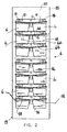
- a high density housing structure 2 for aquatic life including a rack 4, a plurality of aquarium tanks 6, and a water circulation system 8, especially shown in Figs. 1 and 2.
- rack 4 comprises a pair of end walls 10, a plurality of longitudinal support beams 12, a plurality of air and water supply conduits 14, and a plurality of tank hangers 16 that form lateral support beams.
- End walls 10 may be formed as integral sheets of structurally rigid material or may comprise a matrix of legs, trusses or similar structural elements, arranged so as to form a supporting wall at the ends of rack 4. It is also possible that similar vertical structural members could be provided at points spaced inwardly from the longitudinal ends.
- end walls 10 define a plurality of openings 18 that are sized and shaped to accept an end portion of longitudinal support beams 12.
- Means for stabilizing end walls 10 in an upright position can be provided, such as outwardly projecting wings 19 as shown, or base members such as feet (not shown) that cause the end walls 10 to encompass a length and width, for stability.
- Support beams 12 comprise elongated structural members (see also Fig. 3 ), having a plurality of aligned, equally spaced attachment points, such as spaced vertical holes defined on a top side.
- support beams 12 are of metal tubing having a square or rectangular cross-sectional shape, for example a square tubing one inch (2.5 cm) on a side.
- At least one support beam 12 at the rear or rack side of the tanks is also provided at each vertical level or tier, with a plurality of relatively narrow rods 21 (see Figs. 4 and 9 ) that project laterally outwardly, perpendicular to the longitudinal axis of the beam.
- the evenly spaced attachment points are located between cage positions.
- the rods 21 are provided at each cage position, as valve operator pins, discussed in more detail below.
- the air and water supply conduits 14 comprise tubular members defining the flowpaths for air and water.
- conduits 14 comprise an integral extrusion with multiple distinct lumens for air supply, water supply and water drainage.
- conduits 14 each have individually defined and mutually segregated internal passageways extending along their length.
- air and water supply conduits 14 have a square or rectangular cross-sectional shape.
- a plurality of openings 25 are defined in a side wall of each air and water supply conduit 14 so as to provide access to a fresh water supply passageway 26, a pressurized air supply passageway 27, and a drain or waste water removal passageway 28.
- At least one internal wall of each air and water supply conduit 14, that defines the passageways 26, 27, 28 also includes at least one opening 32, 33, 34, respectively, arranged to communicate with the interior of each aquarium tank 6, via water circulation system 8, when that tank 6 is in place in the rack.
- Tank hangers 16 each comprise a generally rectilinear structural support element having a central web 38 and a plurality of transversely defined openings 40 and 42.
- the transversely defined openings 40 are sized and shaped to accept a portion of support beams 12 and openings 42 are sized and shaped to accept a portion air and water supply conduits 14, the beams and conduits 12, 14 forming longitudinal elements and the lateral tank hangers 16 forming lateral elements coupled to the longitudinal elements to provide a supporting rack.
- These elements need to be sufficiently heavy to bear the load of the aquarium tanks when they are filled with water, namely approximately 62 lbs. per cubic foot, with additional strength for purposes of durability.
- Each opening 40, 42 is surrounded by a flange 44 that projects outwardly perpendicular to central web 38 (that is in a longitudinal direction), which securely fixes the perpendicular orientation of the longitudinal and lateral parts.
- a peripheral flange 46 is provided along a bottom edge of tank hanger 16 in spaced relation to a bottom portion of flange 44 so as to form a channel 48 that is inclined inwardly.
- channels 48 are inclined inwardly from both sides, but a one-sided arrangement is also possible. As best shown in Figs. 2, 4 and 9, channel 48 extends the length of tank hanger 16 and opens at ends 52, 54.
- Channel 48 is sloped downwardly from each end 52, 54 of tank hanger 16, toward a central section 55 of tank hanger 16. Thus channel 48 defines a low point at approximately the central point of tank hanger 16.
- a pair of brackets 58 project downwardly and outwardly from the portion of peripheral flange 46 that is adjacent to central section 55. Brackets 58 define a pair of opposed and spaced channels 60 that are sized and shaped to receive a portion of water circulation system 8, as further discussed below.
- the system comprises a plurality of aquarium tanks 6, wherein a number of fish or other aquatic animals can be housed.
- the tanks can separate the fish, for example, to segregate breeding fish, to protect certain fish (e.g., fry) from predation, to contain a group of fish that have been subjected to an experimental procedure or perhaps are a control group, to contain different species, to disperse a large number of fish throughout the volume of all the tanks, or for any other reason.
- each of the aquarium tanks 6 comprises an open-topped container with a cover.
- the tank 6 comprises a generally frusto-pyramidal receptacle, having walls that preferably slope somewhat inwardly toward the bottom, including side walls 61, end walls 62, a bottom 64, and a cover 66.
- Aquarium tanks 6 shown in Figs. 1 and 2 can be fabricated in different sizes as needed to hold a required volume of water, such as tanks holding 0.5, 1.0, or 1.5 gallons depending upon the number of fish that will be housed in the tank. It is also possible to provide single width tanks and double width tanks, the latter holding substantially twice the volume of water of the former.
- a one gallon aquarium tank can readily house up to 50 fish or more, depending on the size of the fish, the rate at which necessary utilities are provided (e.g., the rate at which the water is changed or oxygenated, the amount and schedule of feeding and so forth).
- Preferably 5 to 50 fish of the size range of zebrafish are housed in a one gallon tank.
- the pump and fluid flow means should be capable of providing the equivalent of 2 to 5 tank volume changes per hour, preferably 3 to 4 tank volume changes per hour, to each aquarium.
- a nominal range of appropriate flow rates is 4.4 to 22 gallons per hour of water to each aquarium.
- the one gallon aquarium tank can readily house 5 to 10 fish as subjects for experimentation, or as many as 40 to 50 fish for stocking or temporary holding. With relatively greater fish density, it is advisable to employ relatively greater aeration by virtue of the air bubbling flow rate, as known in the aquaculture art.
- the internal volume of the aquarium can be subdivided by a barrier that confines adult fish and passes fry, to protect the fry in a breeding situation. Being smaller fish, the density of fry per unit of volume can be higher at a given oxygenation level.
- Aquarium tanks 6 are preferably formed as unitary injection molded clear plastic containers.
- the material preferably is a high temperature polycarbonate if autoclaving will be used as a part of the tank maintenance procedure.
- An outwardly projecting flange 68 is formed around the peripheral edge of the open top end of each aquarium tank 6, see Figs. 4 to 8 .
- Flange 68 forms a shoulder 69 that also substantially surrounds open top end of aquarium tank 6.
- One of end walls 62 includes a U-shaped opening 70 that separates flange 68 and shoulder 69 at the top portion of that end wall 62.
- the inner edges of U-shaped opening 70 form an inwardly projecting flange 72 that further defines opening 70.
- the bottom 64 of the tank comprises inner side surfaces that slope inwardly and downwardly, preferably at a sharper angle adjacent that bottom than higher in the tank.
- the inwardly sloping bottom panels intersect one another to form an elongated trough or sump channel 76 extending the length of the tank.
- Sump channel 76 defines the lowest portion of aquarium tank 6, and in the embodiment shown is positioned centrally along bottom 64.
- Sump channel 76 also extends parallel to the top edge and flange 68 in the embodiment shown, such that channel 76 has a downward gradient to a point only when the tank is tilted, such as when supported in the rack.
- the sump channel 76 can be placed along one side or the other instead of centrally or can be diagonal or otherwise formed, and sump channel 76 can be inclined relative to the flange.
- Each of these structures may be arranged to provide a bottom inside contour that defines a gradient leading from all points on the bottom to a predetermined point from which sediment can be collected by appropriately locating the drain inlet.
- bottom 64 has a substantially "V" or "U” shaped cross-sectional profile parallel to the flange edge and the tank is tilted when supported in the rack, for example by about 5 degrees or an approximate slope of 1:12.
- the bottom may vary in thickness in order to provide the trough shaped inside surface, but preferably the bottom has a substantially even thickness, which makes the outer side of the bottom into a V- or U-shape.
- two elongate, mutually parallel leg ridges 88 extend longitudinally along the bottom 64 between the low point and the side walls, extending at least to the same level as the bottom of the V- or U-shape, and possibly longer, such that the tank is stable when on a horizontal surface, resting along two or three lines.
- two legs 88 are provided, one adjacent to each side wall, namely at the maximum available spacing.
- the V- or U-shape can be asymmetrical such that the low point is near one side wall and only one leg is provided between the low point and the other sidewall, for support along two lines.
- legs 88 are arranged so that when aquarium tank 6 is removed from rack 4, it may be placed on a flat surface in an upright position without the top edge of the tank being tilted in either direction relative to the flat surface.
- Cover 66 closes over the top of each tank and prevents water from dripping or sloshing into a lower tank from an upper one.
- Cover 66 comprises a substantially flat sheet of clear material, e.g., polycarbonate polymer, or the like, or of the same material as the tank, that is sized and shaped to close-off the open top end of aquarium tank 6.
- Cover 66 includes a lip 80, an anti-condensation rib 82, and an air/water supply header 84.
- Lip 80 projects downwardly from a peripheral edge to circumscribe the bottom surface of cover 66, and is sized to fit snugly over flange 68 of aquarium tank 6.
- Anti-condensation rib 82 projects downwardly from the bottom surface of cover 66, and is spaced inwardly from lip 80 so as to reside somewhat within the flange along the upper edge.
- Anti-condensation rib 82 is relatively narrow and protrudes from the underside of cover 66, for example by about 0.125 inches or so.
- Anti-condensation rib 82 can be continuous around the periphery of the lid at a position inside the flange of the tank.
- a jogged portion adjacent to an end of cover 66 can be included so as to provide clearance for portions of water circulation system 8 while nevertheless providing a rib all around the periphery.
- Rib 82 provides a low elevation point from which water that condenses on cover 66 will tend to drip back into the tank.
- Rib 82 is preferably placed to reside immediately adjacent to flange 68. Without such an anti-condensation rib 82, there is a tendency for condensation on cover 66 to flow between cover 66 and the flange 68 of tank 6, particularly by capillary action. The humidity inside the tank is high.
- the water temperature (e.g., 85 degrees F) is higher than ambient temperature (e.g., 70 degrees), which tends to make the cover cooler than the air in the tank and produces condensation at a steady rate.
- ambient temperature e.g. 70 degrees
- the aeration bubbling also produces a positive pressure in the tank relative to ambient and these aspects can combine to cause upper tanks to drip onto lower tanks unless such a rib 82 is provided.
- Air/water supply header 84 projects upwardly from the top surface of cover 66, adjacent to the outer end in the embodiment shown, and encloses or defines a void space or cavity 85.
- Air/water supply header 84 comprises an air bulkhead 90 having a surface 94 that faces toward the top surface of cover 66 and a water bulkhead 92 having a surface 96 that faces toward the top surface of cover 66, see especially Fig. 7 .
- Surface 96 slopes away from the top surface of cover 66 at an angle greater than the tilt angle of the tank when in the rack, for example 10 degrees versus 5 degrees. As a result, surface 96 is inclined outwardly relative to vertical when the tank is in the rack.
- Surface 94 can be oriented substantially perpendicular to the top surface of cover 66, and therefore perpendicular to the flanges that support the tank.
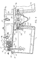
- Fig. 4 illustrates the drain structures and air supply structures
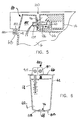
- Fig. 5 illustrates the water supply structures.
- the air and water supply structures are alongside one another on header 84 of cover 66, see Figs. 6 and 7.
- Each surface 94, 96 includes one opening into cavity 85 that interfaces with fresh water supply passageway 32 of water supply 8, as shown in Fig. 5, and a second opening that couples to pressurized air supply passageway 34 as shown in Fig. 4.
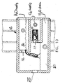
- a waste water removal passageway 36 is also provided in the multiple lumen conduit; however the waste water passageway 36 does not interface with the cover or the tank. Instead, waste water passageway 36 is provided at the utility supply header to remove supply water flowing directly from the supply water passageway when the tank is not inserted in the rack so as to intercept the flow of supply water.
- This supply flow (see Fig. 10 ) is provided at each tank location, from the water supply passageway to the waste water removal passageway. When the tank is inserted in rack 4 (see Fig. 5), this flow is intercepted and flows
- FIG. 11 schematically illustrates the water flow path, namely a closed circuit including a pump and filter and controls, a biocidal element such as a UV source, and any tanks 6 that are .
- the water circulation system 8 comprises a water and air inlet assembly 100 and a water and waste outlet assembly 200 (see Figs. 4 and 5).
- Water and air inlet assembly 100 comprises an aspirator subassembly 105 and a water cradle 110 that are supported by air/water supply header 84 on the tank cover 66.
- Aspirator subassembly 105 includes a spring actuated ball valve 113, a valve engagement coupling 115, and an aspirator tube 118.
- Spring actuated ball valve 113 comprises a tubular housing 121 (see Fig.
- the tubular housing is cylindrical along a portion of its length and tapers at an distal end where the ball valve is engaged to open the air supply when tank 6 is inserted into the rack.
- a portion of the outer surface of the tubular housing is threaded and engages with a corresponding portion of the wall 94 of air and water supply conduit 14 that defines an inner portion of pressurized air supply passageway 27.
- Valve engagement coupling 115 comprises an elongated tube having an outer diameter that is less than the diameter of the opening defined at tapered outer end 127 of tubular housing 121.
- a threaded portion 128 of valve engagement coupling 115 engages a corresponding threaded portion of the wall of air/water supply header 84 that defines the opening in surface 94 of air bulkhead 90.
- An annular sealing flange can be disposed on the outer surface of valve engagement coupling 115, adjacent to threaded portion 128 for sealing purposes.
- Supply air is fed when the valve is open to aspirator tube 118, namely an elongated having an open upper end that is threaded along the outer surface of the tube, and threads into an elbow fitting 131 within the air bulk head 90.
- Fitting 131 provides a right-angled passageway and receives the threaded portion of valve engagement coupling 115, substantially along a horizontal axis, and aspirator tube 118 substantially vertically so that aspirator tube 118 projects at least partially under the water level that fills aquarium tank 6.
- the water level is maintained (see Fig. 4) by discharge from a drain at the rear of tank 6. Inasmuch as tank 6 is tilted inwardly of the rack, the water level falls well below the drain level when tank 6 is removed from the rack and placed on a horizontal support. Additionally, when tank 6 is removed a spring biases ball valve at the drain also closes.
- water cradle 110 For supply of water (see Figs. 5 and 7), water cradle 110 comprises a semi-tubular structure including an elongated semi-cylindrical portion 136, a tubular portion 139, and an annular sealing flange 141 projecting radially outwardly from the transition between semi-cylindrical portion 136 and tubular portion 139.
- Tubular portion 139 is threaded on an outer surface for engagement with a corresponding threaded portion of the wall of air/water supply header 84 that defines the opening in surface 96 of water bulkhead 92.
- Annular sealing flange 141 is sized and shaped so as to sealingly abut surface 96 when water cradle 110 is installed in water bulkhead 92.
- Semi-cylindrical portion 136 forms a spoon-like receptacle that projects outwardly from the center of annular sealing flange 141 and away from surface 96. Because surface 96 is sloped away from the top surface of cover 66 at an angle greater than the tilt angle of the tank (e.g., about 10 degrees versus 5 degrees), semi-cylindrical portion 136 is oriented at a downwardly sloping angle (equal to the difference between the tank tilt angle and the water bulkhead-to-cover angle). As a result, water that is poured into semi-cylindrical portion 136 flows by gravity along a downward gradient toward water bulkhead 92, into and through tubular portion 139 to feed the tank.
- waste water outlet assembly 200 draws from the lowermost point in the tank and discharges into a waste water drain 210, namely an at-least-partly open longitudinal trough provided at each vertical tier.
- Each drain 210 is coupled into the return side of the circulating water flowpath, leading back to the filter and the pump that drives the flow. Wastewater passage 28 also leads back to the return side, although the waste water in passage 124 has not passed through a tank 6.
- the waste water outlet assembly 200 comprises a housing 202, a discharge tube 204, a spring actuated ball valve 206, a tank interface grommet 208, and the waste water drain 210.
- Housing 202 is sized and shaped to be positioned within an upper portion of aquarium tank 6, adjacent to cover 66 and end wall 62, and in confronting relation to U-shaped opening 70.
- An internal void or cavity is defined within housing 202 and has right angle openings respectively sized to accept a portion of spring actuated ball valve 206, and arranged in flow communication with a discharge inlet passageway 215, through which water is drained from tank 6.
- the stop for the ball valve is provided by the discharge tube 204.
- Discharge inlet tube or passageway 215 projects downwardly from a bottom surface of housing block 202.
- Discharge inlet passageway 215 and discharge outlet passageway 204 are oriented at approximately ninety degrees to one another, and are in selective flow communication with operation of the ball valve.
- Anti-siphoning passageway 219 opens onto a top surface of housing 202 so as to be in communication between internal cavity 213 and the ambient atmosphere surrounding housing 202. Passageway 219 prevents a siphoning action that could otherwise lower the water level in the tank below the nominal level defined by the high point of the drain flow path. As thus configured, discharge of spent water from each tank 6 in the rack is driven by gravity and the tank water is regularly exchanged with fresh water.
- each tank substantially protects the tank from ingress of water spilled from a tank higher in the rack (see Figs. 7 to 9).
- the spring biased valve in the waste water discharge from tank 6 closes off the drain flowpath when tank 6 is removed from the rack.
- spring-actuated ball valve 206 comprising a helical spring 224 and a ball-stop defined by the end of tube 204, closes when tank 6 is pulled a short distance along its supporting flanges in the removal direction, as shown on the left side of Fig. 9, or opens when tank 6 is fully inserted as shown on the right side of Fig. 9.
- Helical spring 224 is disposed in internal cavity 213 and urges the valve body or ball toward ball-stop 226 and a sealing engagement blocking off both discharge inlet passageway 215 and discharge through outlet tube 204.
- the valve is opened and drainage can occur by pushing back the ball 206 when the tank is fully inserted into the rack, namely via valve operator pin 21 that is fixed in the central structure of the rack and protrudes laterally in the area just above the longitudinal drain trough.
- Drain tube 204 projects outwardly from the discharge outlet passageway to discharge used or spent water over U-shaped opening 70 and into trough 210.
- Tube 204 is cylindrical where it projects from a side of housing 202 and is encompassed by a tank interface grommet 208 that mechanically engages with and seals to U-shaped opening 70.
- Grommet 208 is made of elastomeric material and has a U-shaped slot around its sides and bottom which fits snugly into opening 70.
- the grommet has a central opening sealing with tube 204, and preferably also has tabs or ears protruding laterally in opposite directions, the tabs or ears resting on and against tank flange 68 at its outward bend 69.
- Tank interface grommet 208 is mated with aquarium tank 6 by slidingly engaging inwardly projecting flange 72 of U-shaped opening 70 with the peripheral U-shaped groove along the sides and bottom of grommet 208. At the lower limit of displacement of grommet 208, the grommet ears abut against flange 68 at the top portion of end wall 62 of tank 6.
- the tank interface grommet 208 including its U-shaped peripheral slot and the ears that rest on and against tank flange 68, precisely defines the vertical position of the drain tube 215. Positioning by virtue of the grommet provides a means to accurately set the height of the gap between the bottom of the tank and the drain inlet tube 215. In particular, the grommet positions the drain assembly so that the lower end of inlet tube 215 is spaced a short distance, for example 0.125 inch, from the lowermost point in the trough in the bottom of tank 6 by which sediment moves toward the low point and the drain, at the back of the tank.
- the gap forms a restricted cross sectional dimension of the flow path of water from tank 6 into drain tube 215, and thus locally increases the velocity of the water flow at the gap. This helps to entrain and remove solids that have settled in the tank, and reduces the need for regular cleaning of tank 6 to remove sediment.
- Waste water drain 210 comprises a longitudinally elongated trough or upwardly open channel that in the dual sided rack embodiment shown in positioned along the central interior portion of rack 4, below the support beam 12. Rods 21, forming the ball valve operators, are disposed between the supports that project downwardly from lateral beam 16 below the level of the tank-carrying flanges thereof. The trough can be snapped into engagement with lateral beams at spaced points by the brackets formed between the two downwardly projecting supports. Waste water drain 210 is located below drain tubes 228 for all of aquarium tanks 6 assembled in rack 4 so that drain water pours from the drain assemblies into trough 210.
- a trough 210 is provided for each vertical tier of tanks, all of the troughs draining into conduits or into a common conduit (not shown) at an end of the rack and leading back to the circulating path of the water and to the filter apparatus and water pump.
- the openings of the multiple lumen supply conduit 14 at each tier can be separately connected by flexible tubes or coupling to filtered and purified water supplied at pressure by the circulating pump, to a supply of compressed air and to a negative pressure or gravity fed return line leading to the pump and filter.
- the conduits can be coupled on one or both sides (and on each side of the rack for the dual-sided embodiment shown) to make these connections.
- such an arrangement would involve a rather complex network of tubes and connections.
- An embodiment of the invention as shown comprises a vertically oriented multiple lumen conduit that corresponds to and is in flow communication with the corresponding openings of the multiple lumen air/water supply and waste water drain at each vertical level or tier (see Fig. 10).
- one end of the multiple lumen conduit 14 is capped off by a sealing cover (not shown) that can be affixed by adhesive or heat welding, etc.
- the opposite end of the multiple lumen conduit 14, namely the end shown in Fig. 10 is capped by a sealed coupling cap that has openings to couple in fluid communication the respective subdivisions of the multiple lumen conduit 14 with corresponding subdivisions of a vertical multiple lumen conduit.
- the sealing coupling cap is attached by adhesive or welding at a connection end.
- This coupling cap has flow openings that preferably comprise flanged openings with O-ring seals. Corresponding openings are provided in the vertical multi-lumen conduit, and seal with the flanged openings and O-rings.
- a bolt can be provided for urging the conduits into sealing engagement at each level or tier. In this arrangement it is only necessary to provide one connection for each of the three lumens of conduit 14 for each side of the rack (or for the whole rack in a one-sided version).
- a similar conduit (not shown) can couple to the ends of drain troughs 210 at least at one side of the rack and at each level. That connection can be made by a vertical conduit with space holes into which the troughs 210 extend.
- the water supply, waste water drain and air supply couplings are all made to the multiple lumen conduit on the same end, which provides a neat and compact arrangement because it is only necessary to make connections to the vertical multiple lumen conduit, e.g., at the bottom or top, to couple that side of the rack into the circulating flow path. It is also possible to make some of the connections at one end (e.g., the supplies of air and water) and others at the opposite end (the waste water drain) such that certain flows move in opposite directions. In lieu of multiple lumen conduits as discussed herein, it is also possible to arrange the same flow connections using separate (or attached) single lumen conduits for each separate flow at each tier.
- the structural parts of the device are readily put together and taken apart.
- the user can generally determine which end of the rack should have couplings, how many levels or tiers will be included, the longitudinal length of the rack and similar aspects of a particular installation. For example if the utility (air/water/drain) connections are to be moved to the opposite side of the rack, their conduits can be moved from one side of the rack to the other and reversed end for end.
- a standardized unit is also possible, namely having a particular width and number of tiers, and in the embodiment shown, a roll-out shelf in the middle (shown in broken lines) for servicing tanks, such as transferring subjects from one tank to another.
- the ability to couple the lateral beams 16 to longitudinal members 12 also permits mixing single width tanks and multiple width tanks, as shown by the double width tank in the bottom tier of Fig.1.
- one or more lateral beams can be detached and slid along members 12 to abut against the adjacent beam.
- the water circulation system runs at a constant flow rate for changing the water in all the tanks at approximately the same frequency.
- the circulation system is driven with sufficient power to produce a positive pressure in the water supply conduits and a negative pressure in the drain conduits, as necessary to drive the flow.
- the vertical spacing of the tiers provides a fluid head that affects the pressures at each level. That is, the weight of the volume of water that is higher in the rack bears on the conduits at lower elevation.
- the rate of supply water flow could be substantially higher at the lower tiers and the rate of drainage substantially higher at the upper tiers. This situation can be remedied in a number of ways.
- the dimensions of the conduits can be arranged such that the orifices between the vertical and horizontal conduits are small in cross section compared to the vertical multiple lumen conduit, which causes the vertical conduit to act as a header or weir pipe arrangement.
- the driving pressures can be relatively high compared to the difference in pressure due to fluid head, which tends to equalize the flow rates at the respective tiers.
- progressively greater restrictions can be placed in the supply lines at lower elevations and/or the drain lines at higher elevations to balance the effect and achieve equal flow. Provided the drain negative pressure is sufficient to achieve a positive flow at least equal to the supply flow, it is normally only necessary to adjust for the flow rate on the supply side.
- Adjusting the rate of water supply inherently governs the rate of total flow in the drains because only that amount is available to drain.
- the volume of the flow draining through the drain passageways of the multi-lumen horizontal conduits versus the volume draining through the rear drain troughs varies as a function of the proportion of tank locations that are occupied by tanks. With no tanks in the rack, all the drain flow is through the multi-lumen conduits. With all tank positions occupied, most or all of the drain flow is through the rear trough.
- the flow in the horizontal conduits is gravity flow rather than pressure driven, because these conduits are open to the ambient and operate at ambient pressure.
- the drain conduits are preferably tilted slightly toward one end of the rack, and all the drain connections are made there.
- the tilt can be obtained by placing the support positions on one end of the rack higher than the other but keeping the end supporting structures vertical such that the vertical and horizontal members form a parallelogram.
- the connected vertical and horizontal members can be at precise right angles and the overall structure tilted toward one end or the other by providing a spacer under one end.
- substantially all the surfaces that are in contact with the water on the supply and drain sides can be substantially free of metal surfaces.
- Metal ions can be toxic to some aquatic animals and plants.
Landscapes
- Life Sciences & Earth Sciences (AREA)
- Environmental Sciences (AREA)
- Zoology (AREA)
- Biodiversity & Conservation Biology (AREA)
- Animal Husbandry (AREA)
- Clinical Laboratory Science (AREA)
- General Health & Medical Sciences (AREA)
- Health & Medical Sciences (AREA)
- Animal Behavior & Ethology (AREA)
- Marine Sciences & Fisheries (AREA)
- Farming Of Fish And Shellfish (AREA)
- Catching Or Destruction (AREA)
- Pharmaceuticals Containing Other Organic And Inorganic Compounds (AREA)
- Housing For Livestock And Birds (AREA)
Applications Claiming Priority (2)
| Application Number | Priority Date | Filing Date | Title |
|---|---|---|---|
| US434644 | 1982-10-15 | ||
| US09/434,644 US6305324B1 (en) | 1999-11-05 | 1999-11-05 | High density housing for aquatic animals |
Publications (3)
| Publication Number | Publication Date |
|---|---|
| EP1099376A2 true EP1099376A2 (de) | 2001-05-16 |
| EP1099376A3 EP1099376A3 (de) | 2001-11-21 |
| EP1099376B1 EP1099376B1 (de) | 2011-05-18 |
Family
ID=23725055
Family Applications (1)
| Application Number | Title | Priority Date | Filing Date |
|---|---|---|---|
| EP00124114A Expired - Lifetime EP1099376B1 (de) | 1999-11-05 | 2000-11-06 | Fischkäfig hoher Dichte |
Country Status (5)
| Country | Link |
|---|---|
| US (2) | US6305324B1 (de) |
| EP (1) | EP1099376B1 (de) |
| AT (1) | ATE509521T1 (de) |
| CA (1) | CA2325245C (de) |
| DK (1) | DK1099376T3 (de) |
Cited By (4)
| Publication number | Priority date | Publication date | Assignee | Title |
|---|---|---|---|---|
| WO2004016080A1 (en) * | 2002-08-16 | 2004-02-26 | Square Forest South Africa (Pty) Limited | Aquarium |
| EP3194298A4 (de) * | 2014-09-17 | 2018-04-18 | 3283688 Nova Scotia Limited | Meeresfrüchtebehälter |
| ES2712348A1 (es) * | 2017-11-10 | 2019-05-10 | Univ Cadiz | Sistema de mantenimiento individual de organismos acuáticos vivos. |
| US20250143270A1 (en) * | 2023-11-07 | 2025-05-08 | Anh Ngoc Le | Live crustacean storage system |
Families Citing this family (38)
| Publication number | Priority date | Publication date | Assignee | Title |
|---|---|---|---|---|
| US6729266B1 (en) * | 2000-11-03 | 2004-05-04 | Lab Products, Inc. | Animal isolation and caging system |
| US6553939B1 (en) * | 2002-02-08 | 2003-04-29 | Getinge/Castle, Inc. | Method of changing the cages of laboratory animals, and racks for use therewith |
| US7320294B2 (en) * | 2002-10-25 | 2008-01-22 | Lab Products, Inc. | Cage and rack system for housing animals in cages having different widths |
| TWI221401B (en) * | 2003-09-08 | 2004-10-01 | Ind Tech Res Inst | Device and method for culturing and maintaining aquatic crustaceans |
| US20060005778A1 (en) * | 2003-12-18 | 2006-01-12 | Industrial Technology Research Institute | Method and device for cultivating and maintaining aquatic crustaceans |
| US7174850B2 (en) * | 2004-08-30 | 2007-02-13 | Shyh-Min Tom Hsiao | Multi-layered aquaculture system |
| US7000567B1 (en) * | 2004-08-30 | 2006-02-21 | Shyh-Min Tom Hsiao | Method for guiding aquatic crustaceans by utilizing their biological tendency responding to bright and dark contrast |
| US7503283B2 (en) * | 2004-10-24 | 2009-03-17 | Nathaniel Abraham | Aquatic egg collection research system and related devices for implementing the system |
| US20070169715A1 (en) | 2004-12-13 | 2007-07-26 | Innovive Inc. | Containment systems and components for animal husbandry |
| US8156899B2 (en) | 2004-12-13 | 2012-04-17 | Innovive Inc. | Containment systems and components for animal husbandry: nested covers |
| US7954455B2 (en) | 2005-06-14 | 2011-06-07 | Innovive, Inc. | Cage cover with filter, shield and nozzle receptacle |
| DE602005006789D1 (de) * | 2005-07-12 | 2008-06-26 | Tecniplast Spa | Behälter für Wassertiere, insbesondere für Versuchstiere, und Gehäusesystem |
| WO2007148211A1 (en) * | 2006-06-22 | 2007-12-27 | Power Robert M | Culture tank for marine organisms |
| WO2008127998A1 (en) | 2007-04-11 | 2008-10-23 | Innovive, Inc. | Animal husbandry drawer caging |
| US8181391B1 (en) * | 2008-03-14 | 2012-05-22 | INKA Biospheric Systems | Vertical aquaponic micro farm |
| WO2012051124A2 (en) | 2010-10-11 | 2012-04-19 | Innovive, Inc. | Rodent containment cage monitoring apparatus and methods |
| USD648077S1 (en) | 2010-12-23 | 2011-11-01 | Umbra Llc | Aquarium assembly |
| US9655350B2 (en) * | 2012-09-14 | 2017-05-23 | New PCA, LLC | Fish display and water circulation apparatus having individually removable live fish containers |
| US9655348B2 (en) * | 2012-09-14 | 2017-05-23 | New PCA, LLC | Fish display and water circulation apparatus with individually removable live fish containers |
| US10743524B2 (en) | 2013-03-07 | 2020-08-18 | It's Lit Lighting Solutions Llc | Containment system for aquatic animals |
| DE102013010828B4 (de) * | 2013-06-19 | 2015-01-08 | Alfred-Wegener-Institut Helmholtz-Zentrum für Polar- und Meeresforschung | Verfahren zur Erzielung eines Wasseraustauschs und Aufzuchtvorrichtung für Wassertiere zur Durchführung des Verfahrens |
| US10729098B2 (en) | 2013-07-01 | 2020-08-04 | Innovive, Inc. | Cage rack monitoring apparatus and methods |
| US10039244B2 (en) * | 2014-03-04 | 2018-08-07 | Greenonyx Ltd | Systems and methods for cultivating and distributing aquatic organisms |
| USD734898S1 (en) | 2014-03-10 | 2015-07-21 | Elive Llc | Aquatic animal container |
| CA3185829A1 (en) | 2014-07-25 | 2016-01-28 | Innovive, Inc. | Animal containment enrichment compositions and methods |
| CN106305569B (zh) * | 2015-06-19 | 2018-06-15 | 北京爱生科技发展有限公司 | 自洁净内循环控温型养殖系统 |
| US10779516B2 (en) | 2015-07-14 | 2020-09-22 | Jellyfish Art, Llc | Aquarium housing for viewing aquatic life including systems and methods associated therewith |
| US10687509B1 (en) * | 2016-09-29 | 2020-06-23 | Vium, Inc. | Feedthrough electrical connection, and experimental animal cages and monitoring systems including the same |
| US10820568B2 (en) | 2016-10-28 | 2020-11-03 | Innovive, Inc. | Metabolic caging |
| US9775330B1 (en) * | 2017-06-07 | 2017-10-03 | Chun-Ku Chen | Aquaponic system |
| US11140882B2 (en) * | 2018-05-30 | 2021-10-12 | Iwaki America Incorporated | Tank system and method |
| US11771240B2 (en) | 2018-10-17 | 2023-10-03 | GloFish, LLC | Containment system for the display of animals |
| KR102899887B1 (ko) | 2019-02-18 | 2025-12-18 | 엘지전자 주식회사 | 식물 재배 장치 |
| KR102899669B1 (ko) * | 2019-02-18 | 2025-12-12 | 엘지전자 주식회사 | 식물 재배 장치 |
| CN112400776B (zh) * | 2020-10-30 | 2022-12-06 | 南京市高淳区麒麟服饰有限公司 | 一种可提高鮸鱼成活率的养殖设备及方法 |
| CN113179998A (zh) * | 2021-05-25 | 2021-07-30 | 广西壮族自治区水产技术推广站 | 一种陆基圆池鱼菜共生循环水养殖系统 |
| CN113841655B (zh) * | 2021-11-10 | 2022-09-20 | 中国水利水电第七工程局有限公司 | 一种基于水环境处理的鱼类养殖环境净化系统及方法 |
| NO349259B1 (en) * | 2024-04-26 | 2025-11-17 | Elevate Ocean | Apparatus for Cultivating Aquatic Organisms |
Citations (10)
| Publication number | Priority date | Publication date | Assignee | Title |
|---|---|---|---|---|
| US32113A (en) | 1861-04-23 | Henry bailey | ||
| US4690100A (en) | 1985-10-22 | 1987-09-01 | Thoren Caging Systems, Inc. | Ventilated animal housing and service system with cage filter covers |
| US5042425A (en) | 1989-11-20 | 1991-08-27 | Frost Jr Robert W | Aquarium and bird and animal containment system |
| US5044316A (en) | 1990-03-28 | 1991-09-03 | Thoren Caging Systems, Inc. | Ventilated animal caging system with cage racks and filter covers including valves operable by rack |
| US5174239A (en) | 1991-05-21 | 1992-12-29 | Sato Kogei Kabushiki Kaisha | Sealed-type aquarium device |
| US5197409A (en) | 1992-03-23 | 1993-03-30 | Hammond Daniel S | Aquatic tank display system |
| US5365886A (en) | 1993-02-19 | 1994-11-22 | Frost Jr Robert W | Aquarium contaiment system |
| US5413070A (en) | 1993-06-24 | 1995-05-09 | California Aquarium Supply Co. | Aquarium display configuration with lighting and cantilevered support rack |
| US5474024A (en) | 1994-10-04 | 1995-12-12 | Thoren Caging Systems, Inc. | Caging system with slide bar operator for quick disconnect water fitting |
| US5513596A (en) | 1993-12-21 | 1996-05-07 | Allentown Caging Equipment Co., Inc. | Assembly for animals with positive disconnect from a watering system |
Family Cites Families (33)
| Publication number | Priority date | Publication date | Assignee | Title |
|---|---|---|---|---|
| US460809A (en) * | 1891-10-06 | aunther | ||
| US475082A (en) * | 1892-05-17 | gxnther | ||
| US1528179A (en) * | 1923-08-13 | 1925-03-03 | Henry L Baldridge | Fish-hatchery pond |
| US3076432A (en) * | 1961-08-28 | 1963-02-05 | Jung Werner | Method and apparatus for preserving and transporting live fish |
| CH476455A (de) | 1967-06-21 | 1969-08-15 | Tomisser Franz | Aquarium |
| US3638616A (en) * | 1970-09-14 | 1972-02-01 | William Jeter Carmouche | Fish-growing aquarium |
| US3828732A (en) * | 1972-06-12 | 1974-08-13 | R Hill | Reverse flow flushing apparatus for animal housing systems |
| US3774575A (en) * | 1972-07-26 | 1973-11-27 | C Patterson | Aquarium |
| US3924571A (en) * | 1973-12-07 | 1975-12-09 | Chirico Lorraine | Animal caging system |
| US3883148A (en) * | 1974-02-11 | 1975-05-13 | Certified Stainless Services | Trailer tank |
| US3927539A (en) * | 1974-04-01 | 1975-12-23 | Ato Inc | Spraying |
| US4147131A (en) | 1977-04-18 | 1979-04-03 | Paul C. Harvey | Elevated aquarium tank |
| USRE32113E (en) | 1979-07-17 | 1986-04-15 | Thoren Caging Systems, Inc. | Air conditioned laboratory rack for animal cages |
| US4343261A (en) | 1979-09-18 | 1982-08-10 | Thomas William R | Animal caging system |
| US4402280A (en) | 1980-11-12 | 1983-09-06 | Thomas William R | Animal caging system |
| JPS58212729A (ja) * | 1982-06-04 | 1983-12-10 | 仁木 資浩 | 小動物飼育装置 |
| US4807565A (en) * | 1987-08-06 | 1989-02-28 | Hawthorne Mark A | Gravity filter system aquarium |
| US5014647A (en) * | 1988-03-21 | 1991-05-14 | Woltman Robert B | Fish culture system |
| US4998506A (en) * | 1988-05-23 | 1991-03-12 | Frostad Joseph R | Piggy deck |
| GB2232862B (en) | 1989-06-16 | 1993-03-31 | Chi Shiang Lee | An improved floor board structure for aquaria |
| US5140855A (en) * | 1990-11-13 | 1992-08-25 | Biological Monitoring, Inc. | Monitoring tank modules and array for use with biological sensors |
| US5197627A (en) * | 1991-03-08 | 1993-03-30 | Petrolite Corporation | Double walled storage tank |
| US5148771A (en) * | 1991-09-03 | 1992-09-22 | Schuett Daniel L | Veterinarian infectious waste containment system |
| US5228999A (en) | 1991-12-17 | 1993-07-20 | Yang Hyun W | Method and apparatus for maintaining an artificial aquatic system |
| US5450818A (en) * | 1993-09-29 | 1995-09-19 | Float Culture Systems, Inc. | Floating fish cultivating system and related method |
| US5469810A (en) * | 1994-05-04 | 1995-11-28 | Chiang; Ming-Tsung | Raising control apparatus for living fish and water plants |
| FR2724122B1 (fr) * | 1994-09-02 | 1996-12-06 | Soc D Transformation Ind De Ma | Bassin de decantation de grand diametre destine au traitement des eaux residuaires chargees |
| US5640930A (en) * | 1995-08-17 | 1997-06-24 | Kirby; Michael J. | Automatic cleaning aquarium |
| US5823144A (en) | 1996-02-14 | 1998-10-20 | Edstrom Industries, Inc. | Cage and rack system incorporating automatic water docking system, latch mechanism, and quick-connect coupling |
| US5783070A (en) * | 1997-01-04 | 1998-07-21 | Lee; Chih-Hsiang | Pollutant tray for aquarium |
| US5849185A (en) * | 1997-01-22 | 1998-12-15 | Judy, Jr.; Donald M. | Gravity vacuum system |
| NL1007744C1 (nl) * | 1997-12-09 | 1999-01-12 | Navital S A R L | Werkwijze voor het onafhankelijk van een seizoen opkweken, conditioneren en opslaan van schelp- en schaaldieren en inrichting voor het toepassen van deze nieuwe werkwijze. |
| US6125791A (en) * | 1998-12-01 | 2000-10-03 | Pharmacal Research Laboratories, Inc. | Aquatic housing system |
-
1999
- 1999-11-05 US US09/434,644 patent/US6305324B1/en not_active Expired - Fee Related
-
2000
- 2000-11-06 CA CA002325245A patent/CA2325245C/en not_active Expired - Fee Related
- 2000-11-06 AT AT00124114T patent/ATE509521T1/de active
- 2000-11-06 DK DK00124114.0T patent/DK1099376T3/da active
- 2000-11-06 EP EP00124114A patent/EP1099376B1/de not_active Expired - Lifetime
-
2001
- 2001-10-03 US US09/970,003 patent/US6588371B2/en not_active Expired - Fee Related
Patent Citations (10)
| Publication number | Priority date | Publication date | Assignee | Title |
|---|---|---|---|---|
| US32113A (en) | 1861-04-23 | Henry bailey | ||
| US4690100A (en) | 1985-10-22 | 1987-09-01 | Thoren Caging Systems, Inc. | Ventilated animal housing and service system with cage filter covers |
| US5042425A (en) | 1989-11-20 | 1991-08-27 | Frost Jr Robert W | Aquarium and bird and animal containment system |
| US5044316A (en) | 1990-03-28 | 1991-09-03 | Thoren Caging Systems, Inc. | Ventilated animal caging system with cage racks and filter covers including valves operable by rack |
| US5174239A (en) | 1991-05-21 | 1992-12-29 | Sato Kogei Kabushiki Kaisha | Sealed-type aquarium device |
| US5197409A (en) | 1992-03-23 | 1993-03-30 | Hammond Daniel S | Aquatic tank display system |
| US5365886A (en) | 1993-02-19 | 1994-11-22 | Frost Jr Robert W | Aquarium contaiment system |
| US5413070A (en) | 1993-06-24 | 1995-05-09 | California Aquarium Supply Co. | Aquarium display configuration with lighting and cantilevered support rack |
| US5513596A (en) | 1993-12-21 | 1996-05-07 | Allentown Caging Equipment Co., Inc. | Assembly for animals with positive disconnect from a watering system |
| US5474024A (en) | 1994-10-04 | 1995-12-12 | Thoren Caging Systems, Inc. | Caging system with slide bar operator for quick disconnect water fitting |
Cited By (5)
| Publication number | Priority date | Publication date | Assignee | Title |
|---|---|---|---|---|
| WO2004016080A1 (en) * | 2002-08-16 | 2004-02-26 | Square Forest South Africa (Pty) Limited | Aquarium |
| EP3194298A4 (de) * | 2014-09-17 | 2018-04-18 | 3283688 Nova Scotia Limited | Meeresfrüchtebehälter |
| ES2712348A1 (es) * | 2017-11-10 | 2019-05-10 | Univ Cadiz | Sistema de mantenimiento individual de organismos acuáticos vivos. |
| US20250143270A1 (en) * | 2023-11-07 | 2025-05-08 | Anh Ngoc Le | Live crustacean storage system |
| US12458002B2 (en) * | 2023-11-07 | 2025-11-04 | Anh Ngoc Le | Live crustacean storage system |
Also Published As
| Publication number | Publication date |
|---|---|
| ATE509521T1 (de) | 2011-06-15 |
| DK1099376T3 (da) | 2011-08-15 |
| US6588371B2 (en) | 2003-07-08 |
| EP1099376B1 (de) | 2011-05-18 |
| US20020066414A1 (en) | 2002-06-06 |
| CA2325245C (en) | 2008-12-16 |
| CA2325245A1 (en) | 2001-05-05 |
| EP1099376A3 (de) | 2001-11-21 |
| US6305324B1 (en) | 2001-10-23 |
Similar Documents
| Publication | Publication Date | Title |
|---|---|---|
| US6305324B1 (en) | High density housing for aquatic animals | |
| US5054424A (en) | Aquarium ecosystem | |
| US4684462A (en) | Filtration, aeration, and water level control means for aquariums | |
| KR101923530B1 (ko) | 아쿠아포닉스시스템 | |
| US5042425A (en) | Aquarium and bird and animal containment system | |
| US4844018A (en) | Water supplying system for small-animal cages | |
| US5667671A (en) | Salt water aquarium integrated filter | |
| US5474673A (en) | Top mounted biological filtration system for an aquarium | |
| US5873327A (en) | System and method for cultivating amphibians in captivity | |
| KR20160045245A (ko) | 수조용 올인원 여과 장치 | |
| US7503283B2 (en) | Aquatic egg collection research system and related devices for implementing the system | |
| US6623956B1 (en) | Embryo-culturing incubator assembly | |
| KR101058492B1 (ko) | 활어수족관의 살균정수장치 및 이를 구비한 활어수족관 | |
| US20190320606A1 (en) | Vertical hydroponic grow container | |
| US5297513A (en) | Breeding tank assembly for fish larvae | |
| GB2248558A (en) | Aquarium filter | |
| US4471718A (en) | Apparatus for incubating fish eggs | |
| KR102537864B1 (ko) | 냉난방이 가능한 수경 재배 시스템 | |
| AU700872B2 (en) | A device for purifying water by means of water fleas | |
| US6283061B1 (en) | Terrarium filter plate | |
| KR101572822B1 (ko) | 어류의 인공 부화 장치 | |
| JPH08214726A (ja) | 魚介類飼育用水槽装置 | |
| JP3051200U (ja) | 動物飼育用給水器と該給水器の動物飼育用ケージへの取付構造 | |
| WO2024076262A1 (ru) | Ферма для выращивания гидробионтов | |
| ZA200502733B (en) | Water treatment apparatus |
Legal Events
| Date | Code | Title | Description |
|---|---|---|---|
| PUAI | Public reference made under article 153(3) epc to a published international application that has entered the european phase |
Free format text: ORIGINAL CODE: 0009012 |
|
| AK | Designated contracting states |
Kind code of ref document: A2 Designated state(s): AT BE CH CY DE DK ES FI FR GB GR IE IT LI LU MC NL PT SE TR |
|
| AX | Request for extension of the european patent |
Free format text: AL;LT;LV;MK;RO;SI |
|
| PUAL | Search report despatched |
Free format text: ORIGINAL CODE: 0009013 |
|
| AK | Designated contracting states |
Kind code of ref document: A3 Designated state(s): AT BE CH CY DE DK ES FI FR GB GR IE IT LI LU MC NL PT SE TR |
|
| AX | Request for extension of the european patent |
Free format text: AL;LT;LV;MK;RO;SI |
|
| 17P | Request for examination filed |
Effective date: 20020426 |
|
| AKX | Designation fees paid |
Free format text: AT BE CH CY DE DK ES FI FR GB GR IE IT LI LU MC NL PT SE TR |
|
| RAP1 | Party data changed (applicant data changed or rights of an application transferred) |
Owner name: THOREN AQUATIC SYSTEMS, INC. |
|
| 17Q | First examination report despatched |
Effective date: 20040107 |
|
| GRAP | Despatch of communication of intention to grant a patent |
Free format text: ORIGINAL CODE: EPIDOSNIGR1 |
|
| GRAS | Grant fee paid |
Free format text: ORIGINAL CODE: EPIDOSNIGR3 |
|
| GRAA | (expected) grant |
Free format text: ORIGINAL CODE: 0009210 |
|
| AK | Designated contracting states |
Kind code of ref document: B1 Designated state(s): AT BE CH CY DE DK ES FI FR GB GR IE IT LI LU MC NL PT SE TR |
|
| REG | Reference to a national code |
Ref country code: GB Ref legal event code: FG4D |
|
| REG | Reference to a national code |
Ref country code: CH Ref legal event code: EP |
|
| REG | Reference to a national code |
Ref country code: IE Ref legal event code: FG4D |
|
| REG | Reference to a national code |
Ref country code: DE Ref legal event code: R096 Ref document number: 60045975 Country of ref document: DE Effective date: 20110630 |
|
| REG | Reference to a national code |
Ref country code: CH Ref legal event code: NV Representative=s name: KELLER & PARTNER PATENTANWAELTE AG |
|
| REG | Reference to a national code |
Ref country code: DK Ref legal event code: T3 |
|
| REG | Reference to a national code |
Ref country code: SE Ref legal event code: TRGR |
|
| REG | Reference to a national code |
Ref country code: NL Ref legal event code: VDEP Effective date: 20110518 |
|
| PG25 | Lapsed in a contracting state [announced via postgrant information from national office to epo] |
Ref country code: PT Free format text: LAPSE BECAUSE OF FAILURE TO SUBMIT A TRANSLATION OF THE DESCRIPTION OR TO PAY THE FEE WITHIN THE PRESCRIBED TIME-LIMIT Effective date: 20110919 |
|
| PG25 | Lapsed in a contracting state [announced via postgrant information from national office to epo] |
Ref country code: ES Free format text: LAPSE BECAUSE OF FAILURE TO SUBMIT A TRANSLATION OF THE DESCRIPTION OR TO PAY THE FEE WITHIN THE PRESCRIBED TIME-LIMIT Effective date: 20110829 Ref country code: GR Free format text: LAPSE BECAUSE OF FAILURE TO SUBMIT A TRANSLATION OF THE DESCRIPTION OR TO PAY THE FEE WITHIN THE PRESCRIBED TIME-LIMIT Effective date: 20110819 Ref country code: CY Free format text: LAPSE BECAUSE OF FAILURE TO SUBMIT A TRANSLATION OF THE DESCRIPTION OR TO PAY THE FEE WITHIN THE PRESCRIBED TIME-LIMIT Effective date: 20110518 |
|
| PG25 | Lapsed in a contracting state [announced via postgrant information from national office to epo] |
Ref country code: NL Free format text: LAPSE BECAUSE OF FAILURE TO SUBMIT A TRANSLATION OF THE DESCRIPTION OR TO PAY THE FEE WITHIN THE PRESCRIBED TIME-LIMIT Effective date: 20110518 |
|
| PGFP | Annual fee paid to national office [announced via postgrant information from national office to epo] |
Ref country code: CH Payment date: 20111215 Year of fee payment: 12 Ref country code: SE Payment date: 20111124 Year of fee payment: 12 Ref country code: FI Payment date: 20111123 Year of fee payment: 12 Ref country code: FR Payment date: 20111209 Year of fee payment: 12 Ref country code: DK Payment date: 20111130 Year of fee payment: 12 |
|
| PLBE | No opposition filed within time limit |
Free format text: ORIGINAL CODE: 0009261 |
|
| STAA | Information on the status of an ep patent application or granted ep patent |
Free format text: STATUS: NO OPPOSITION FILED WITHIN TIME LIMIT |
|
| PGFP | Annual fee paid to national office [announced via postgrant information from national office to epo] |
Ref country code: BE Payment date: 20111206 Year of fee payment: 12 |
|
| 26N | No opposition filed |
Effective date: 20120221 |
|
| PGFP | Annual fee paid to national office [announced via postgrant information from national office to epo] |
Ref country code: DE Payment date: 20120130 Year of fee payment: 12 |
|
| REG | Reference to a national code |
Ref country code: DE Ref legal event code: R097 Ref document number: 60045975 Country of ref document: DE Effective date: 20120221 |
|
| PG25 | Lapsed in a contracting state [announced via postgrant information from national office to epo] |
Ref country code: MC Free format text: LAPSE BECAUSE OF NON-PAYMENT OF DUE FEES Effective date: 20111130 |
|
| REG | Reference to a national code |
Ref country code: IE Ref legal event code: MM4A |
|
| PG25 | Lapsed in a contracting state [announced via postgrant information from national office to epo] |
Ref country code: IE Free format text: LAPSE BECAUSE OF NON-PAYMENT OF DUE FEES Effective date: 20111106 |
|
| BERE | Be: lapsed |
Owner name: THOREN AQUATIC SYSTEMS, INC. Effective date: 20121130 |
|
| PG25 | Lapsed in a contracting state [announced via postgrant information from national office to epo] |
Ref country code: LU Free format text: LAPSE BECAUSE OF NON-PAYMENT OF DUE FEES Effective date: 20111106 |
|
| REG | Reference to a national code |
Ref country code: CH Ref legal event code: PL |
|
| REG | Reference to a national code |
Ref country code: DK Ref legal event code: EBP |
|
| REG | Reference to a national code |
Ref country code: AT Ref legal event code: MM01 Ref document number: 509521 Country of ref document: AT Kind code of ref document: T Effective date: 20121106 |
|
| GBPC | Gb: european patent ceased through non-payment of renewal fee |
Effective date: 20121106 |
|
| PG25 | Lapsed in a contracting state [announced via postgrant information from national office to epo] |
Ref country code: LI Free format text: LAPSE BECAUSE OF NON-PAYMENT OF DUE FEES Effective date: 20121130 Ref country code: CH Free format text: LAPSE BECAUSE OF NON-PAYMENT OF DUE FEES Effective date: 20121130 Ref country code: SE Free format text: LAPSE BECAUSE OF NON-PAYMENT OF DUE FEES Effective date: 20121107 Ref country code: AT Free format text: LAPSE BECAUSE OF NON-PAYMENT OF DUE FEES Effective date: 20121106 |
|
| REG | Reference to a national code |
Ref country code: FR Ref legal event code: ST Effective date: 20130731 |
|
| PG25 | Lapsed in a contracting state [announced via postgrant information from national office to epo] |
Ref country code: BE Free format text: LAPSE BECAUSE OF NON-PAYMENT OF DUE FEES Effective date: 20121130 Ref country code: IT Free format text: LAPSE BECAUSE OF NON-PAYMENT OF DUE FEES Effective date: 20121106 Ref country code: FI Free format text: LAPSE BECAUSE OF NON-PAYMENT OF DUE FEES Effective date: 20121106 |
|
| REG | Reference to a national code |
Ref country code: DE Ref legal event code: R119 Ref document number: 60045975 Country of ref document: DE Effective date: 20130601 |
|
| PG25 | Lapsed in a contracting state [announced via postgrant information from national office to epo] |
Ref country code: TR Free format text: LAPSE BECAUSE OF FAILURE TO SUBMIT A TRANSLATION OF THE DESCRIPTION OR TO PAY THE FEE WITHIN THE PRESCRIBED TIME-LIMIT Effective date: 20110518 |
|
| PG25 | Lapsed in a contracting state [announced via postgrant information from national office to epo] |
Ref country code: DE Free format text: LAPSE BECAUSE OF NON-PAYMENT OF DUE FEES Effective date: 20130601 Ref country code: DK Free format text: LAPSE BECAUSE OF NON-PAYMENT OF DUE FEES Effective date: 20121130 |
|
| PG25 | Lapsed in a contracting state [announced via postgrant information from national office to epo] |
Ref country code: GB Free format text: LAPSE BECAUSE OF NON-PAYMENT OF DUE FEES Effective date: 20121106 Ref country code: FR Free format text: LAPSE BECAUSE OF NON-PAYMENT OF DUE FEES Effective date: 20121130 |