EP1099432A2 - Anneau chirurgical de fixation pivotant pour l'utilisation en chirurgie de l'oeil - Google Patents
Anneau chirurgical de fixation pivotant pour l'utilisation en chirurgie de l'oeil Download PDFInfo
- Publication number
- EP1099432A2 EP1099432A2 EP00118816A EP00118816A EP1099432A2 EP 1099432 A2 EP1099432 A2 EP 1099432A2 EP 00118816 A EP00118816 A EP 00118816A EP 00118816 A EP00118816 A EP 00118816A EP 1099432 A2 EP1099432 A2 EP 1099432A2
- Authority
- EP
- European Patent Office
- Prior art keywords
- ring
- sclera
- fixation
- eye
- ring base
- Prior art date
- Legal status (The legal status is an assumption and is not a legal conclusion. Google has not performed a legal analysis and makes no representation as to the accuracy of the status listed.)
- Granted
Links
- 238000001356 surgical procedure Methods 0.000 title claims description 28
- 210000003786 sclera Anatomy 0.000 claims abstract description 49
- -1 polyethylene Polymers 0.000 claims description 8
- 239000012815 thermoplastic material Substances 0.000 claims description 6
- 239000004743 Polypropylene Substances 0.000 claims description 5
- 229920001155 polypropylene Polymers 0.000 claims description 5
- 244000043261 Hevea brasiliensis Species 0.000 claims description 3
- 239000004677 Nylon Substances 0.000 claims description 3
- 239000004698 Polyethylene Substances 0.000 claims description 3
- 239000004793 Polystyrene Substances 0.000 claims description 3
- 229920003052 natural elastomer Polymers 0.000 claims description 3
- 229920001194 natural rubber Polymers 0.000 claims description 3
- 229920001778 nylon Polymers 0.000 claims description 3
- 229920000573 polyethylene Polymers 0.000 claims description 3
- 229920002223 polystyrene Polymers 0.000 claims description 3
- 239000004800 polyvinyl chloride Substances 0.000 claims description 3
- 229920000915 polyvinyl chloride Polymers 0.000 claims description 3
- 229920002725 thermoplastic elastomer Polymers 0.000 claims description 3
- 238000003780 insertion Methods 0.000 claims description 2
- 230000037431 insertion Effects 0.000 claims description 2
- 230000001815 facial effect Effects 0.000 abstract description 5
- 230000013011 mating Effects 0.000 abstract description 4
- 238000000034 method Methods 0.000 abstract description 4
- 238000004140 cleaning Methods 0.000 abstract description 2
- 230000008030 elimination Effects 0.000 abstract 1
- 238000003379 elimination reaction Methods 0.000 abstract 1
- 238000004659 sterilization and disinfection Methods 0.000 abstract 1
- 208000014674 injury Diseases 0.000 description 10
- 230000008733 trauma Effects 0.000 description 10
- 210000004087 cornea Anatomy 0.000 description 5
- 208000002177 Cataract Diseases 0.000 description 3
- 230000003247 decreasing effect Effects 0.000 description 3
- 230000004424 eye movement Effects 0.000 description 2
- 230000000087 stabilizing effect Effects 0.000 description 2
- 230000000472 traumatic effect Effects 0.000 description 2
- 206010015911 Eye burns Diseases 0.000 description 1
- RTAQQCXQSZGOHL-UHFFFAOYSA-N Titanium Chemical compound [Ti] RTAQQCXQSZGOHL-UHFFFAOYSA-N 0.000 description 1
- 230000006378 damage Effects 0.000 description 1
- 230000007812 deficiency Effects 0.000 description 1
- 230000000994 depressogenic effect Effects 0.000 description 1
- 230000000694 effects Effects 0.000 description 1
- 238000000605 extraction Methods 0.000 description 1
- 239000012530 fluid Substances 0.000 description 1
- 238000002513 implantation Methods 0.000 description 1
- 230000002401 inhibitory effect Effects 0.000 description 1
- 230000007794 irritation Effects 0.000 description 1
- 239000003550 marker Substances 0.000 description 1
- 239000000463 material Substances 0.000 description 1
- 238000003825 pressing Methods 0.000 description 1
- 230000006641 stabilisation Effects 0.000 description 1
- 238000011105 stabilization Methods 0.000 description 1
- 229910001220 stainless steel Inorganic materials 0.000 description 1
- 239000010935 stainless steel Substances 0.000 description 1
- 230000000451 tissue damage Effects 0.000 description 1
- 231100000827 tissue damage Toxicity 0.000 description 1
- 229910052719 titanium Inorganic materials 0.000 description 1
- 239000010936 titanium Substances 0.000 description 1
Images






Classifications
-
- A—HUMAN NECESSITIES
- A61—MEDICAL OR VETERINARY SCIENCE; HYGIENE
- A61F—FILTERS IMPLANTABLE INTO BLOOD VESSELS; PROSTHESES; DEVICES PROVIDING PATENCY TO, OR PREVENTING COLLAPSING OF, TUBULAR STRUCTURES OF THE BODY, e.g. STENTS; ORTHOPAEDIC, NURSING OR CONTRACEPTIVE DEVICES; FOMENTATION; TREATMENT OR PROTECTION OF EYES OR EARS; BANDAGES, DRESSINGS OR ABSORBENT PADS; FIRST-AID KITS
- A61F9/00—Methods or devices for treatment of the eyes; Devices for putting in contact-lenses; Devices to correct squinting; Apparatus to guide the blind; Protective devices for the eyes, carried on the body or in the hand
- A61F9/007—Methods or devices for eye surgery
- A61F9/013—Instruments for compensation of ocular refraction ; Instruments for use in cornea removal, for reshaping or performing incisions in the cornea
Definitions
- the field of invention relates to a medical surgical device for stabilizing the eye during surgery. More particularly, the invention relates to a swivel fixation ring for use in corneal surgery.
- cataract extraction and lens implantation surgery has evolved significantly resulting in safer and more predictable outcomes.
- a surgical technique called the clear corneal approach was developed that offered significant advantages over the previous surgical technique for cataract surgery. In this technique, the primary incision is made only through the corneal tissue.
- cataract surgery In cataract surgery, a high degree of precision is required to insure the surgical outcome will be a success. A major concern is location of the incision.
- the incision geometry must be properly sized and located to diminish the chances of complication. Complications include, for example, leakage of the ocular fluid, corneal burn or increasing a pre-operative stigmatism.
- a properly designed scalpel and experienced surgeon are both important in achieving a successful incision.
- the patient is fully alert and can inadvertently move his or her eyes during advancement of the scalpel into the eye. This can cause the sharp edges of the scalpel to uncontrollably widen the incision greater than the width of the scalpel. This widening of incision can lead to unanticipated complications.
- Another potential risk during eye movement is the possibility of incising other intraocular tissues such as the iris or the lens.
- a common design for such a prior art device contains a ring attached to the distal end of the handle fixed at a pre-determined angle.
- a second common type of design for such a surgical fixation ring device has the distal end of the handle with a hinge mechanism that allows the ring to swivel at a variety of angles.
- This swivel design uses multiple components usually a handle welded to an integral fork, a set of two pins and a separate ring. The swivel design is usually preferred over the stationary design in that it can adapt to a variety of positions that provides stabilization of the eye and the ability to clear facial features such as the nose or brow.
- the swivel fixation ring of the prior art design still has a high probability of slipping off the sclera causing the eye to move and potential trauma due to movement of the eye during the initial incision.
- teeth when teeth are employed in the prior art design the teeth tend to cause damage to the sclera and corneal tissue as they cut into the tissue in trying to hold firmly on the eye to reduce slipping.
- Prior art designs that incorporate multiple ribs or grooves cause irritation to the eye due to pinpoint contact on the sclera or corneal tissue.
- a swivel fixation ring that will allow the surgeon to have more surface contact with the eye to assist and secure fixation of the ring during the primary incision.
- a fixation device to have a smaller overall diameter that will allow more clearance between the ring and other facial obstructions so that the surgeon can use other surgical instruments on the eye without interference due to the fixation ring.
- Another improvement needed for the fixation ring device is that the teeth must always be in the correct orientation pointing down.
- the present invention avoids a disadvantage to the prior art by allowing the interior ring surface to match with the curvature of the sclera. This matching of surfaces gives the assistance to secure more tightly to the surface of the sclera without trauma as in the other prior art devices.
- Another objective that is met in the present invention is that due to the nature of the inherent living hinge design, the protrusions or teeth attach to the bottom surface of the ring can grasp the sclera thereby decreasing slippage without producing additional trauma to the eye.
- the living hinge also assists in eliminating the problem of the ring swiveling away from the scleral surface during use as can happen with the prior art device.
- the third object of the present invention is that the overall diameter is smaller by incorporating the living hinges mounted on top of the ring. This smaller diameter assists the surgeon by giving more clearance between the ring and other facial obstructions. Additionally, the device of the present invention eliminates small crevices which were present in the pin section that are hard to clean during re-use.
- a surgical fixation ring device for placement on the sclera during eye surgeries including a handle having a handle base, a shaft and a u-shaped fork.
- the handle is attached to a segmented ring base that has an arcuate bottom.
- the arcuate bottom is designed to mate with the curvature of the sclera of the eye.
- the ring base further includes protrusions or teeth that are used to anchor or eliminate slippage of the ring base from the sclera.
- the ring base is segmented and wraps around the cornea from about 180° to about 270°. This design allows maximum surface contact of the arcuate bottom to the sclera to decrease slippage on the sclera and allows an opening adequate to manipulate surgical instruments such as the scalpel.
- Fig. 1 is a perspective view of a surgical fixation ring device of the prior art.
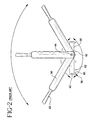
- Fig. 2 is an enlarged side view of the prior art device in Fig. 1 illustrating relative motion of the fixation ring.
- Fig. 3 is a perspective view of the surgical fixation ring device in accordance with the subject invention.
- Fig. 4 is an enlarged view of Fig. 3 illustrating the fixation ring in accordance with the subject invention.
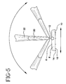
- Fig. 5 is an enlarged side view of the device in Fig. 3 demonstrating relative motion of the fixation ring in accordance with the subject invention.
- Fig. 6 is an enlarged perspective view of the device in Fig. 3 in relation to a human eye.
- Fig. 7 is the device illustrated in Fig. 6 placed on the sclera.
- Fig. 8 is a perspective view of a prior art device placed on the sclera.
- Fig. 9 is a cross-sectional view of the present invention taken along lines 9-9 in Fig. 7.
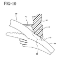
- Fig. 10 is an enlarged cross-sectional view of Fig. 9.
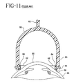
- Fig. 11 is a cross-sectional view of a prior art device taken along lines 11-11 in Fig. 8.
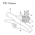
- Fig. 12 is an enlarged cross-sectional view of Fig. 11.
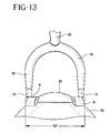
- Fig. 13 is a front view of the present invention relative to the sclera.
- Fig. 14 is a front view of a prior art device relative to the sclera.
- a surgical fixation ring device for placement on the sclera of an eye during surgery in accordance with the subject invention is identified generally by the numeral 2 in Figs. 3-14.
- Figs. 1-2 illustrate a prior art fixation ring device generally identified by the numeral 40 .
- Device 40 includes a handle 54 , a shaft 52 , a u-shaped fork 50 , a ring 42 , and a plurality of pins 44 .
- Handle 54 is connected to shaft 52 which is connected to u-shaped fork 50 .
- U-shaped fork 50 is disposed over ring 42 and attached to ring 42 by pins 44 .
- This configuration allows ring 42 to rotate 360° relative to for 50 as illustrated in Fig. 2.
- Ring 42 further includes a flat bottom 58 which includes teeth 56 .
- Teeth 56 further includes a plurality of spikes 60 that are disposed circumferentially around ring 42 .
- Spike 60 form a sharp point 62 .
- Figs. 1 and 2 illustrate the prior art fixation ring device.
- Ring 42 is able to rotate relative to pin 44 360°.
- the ring can swivel during handling and surgery which can make the ring point up and away from the scleral surface. This movement can force the doctor to stop surgery and possibly drop another instrument to manually rotate the ring back into the position to hold onto the scleral surface.
- Spike 60 contains sharp point 62 which can cause traumatic tissue damage to the sclera when embedded in the scleral surface.
- the handle is allowed to rotate 360° relative to the pin around the ring. Again this feature has a disadvantage of the handle and the ring swiveling out of place during surgery which would require the surgeon to reposition the device on the scleral surface.
- Figs. 3-5 illustrate the present invention of the surgical fixation ring. Shown in Figs. 3 and 4 is surgical fixation ring 2 .
- Surgical fixation ring 2 includes a handle assembly 4 attached to a segmented ring base 6 .
- Handle assembly 4 preferably includes a handle base 16 , a shaft 22 , and a fork 20 .
- Handle base 16 further includes a gripping surface 36 .
- Gripping surface 36 is preferably textured or embossed such that the surgeon is easily able to grasp the device without any slippage of the device from the surgeon's hand.
- the shaft and fork are preferably a unitary structure, however it does not have to be so designed.
- the handle shaft and fork are also preferably a unitary structure.
- the handle would include mating structures to connect to the shaft.
- Such structures would be known to those skilled in the art and include snap-fits, threads, and other types of fasteners.
- the fork is preferably U-shaped however it does not have to be so shaped. Other typical shapes could be used for example a V-shaped or even a single unitary structure such as an arm to the shaft connecting directly to the ring. Additionally, the fork can be eliminated from the present invention and the shaft can be directly connected to the segmented ring.
- the surgical fixation ring device is a unitary structure.
- the handle assembly and the segmented ring base are a unitary structure.
- each individual component can be removably attached from each other.
- the handle can be removably attached from the shaft
- the shaft can be removably attached from the fork
- the fork can be removably attached from the segmented ring.
- This attachment replaceability would enable the surgeon to attach various different fixation rings on the device which would give the surgeon more flexibility during the eye surgery.
- the handle assembly only comprise a handle and a shaft which would be attached to the segmented ring. It is also within the scope of the invention for the handle to be attached to the segmented ring.
- segmented ring base 6 is attached to the handle assembly by at least one living hinge 12 .
- Living hinge 12 is preferably attached on the segmented ring such that the distal end of the living hinge is attached to the top of the segmented ring as shown in Fig. 4.
- This position provides the many advantages to the present invention.
- the segmented ring is unable to rotate 360° as shown in Fig. 5 due to the position of the living hinge.
- the present invention provides the surgeon with a fixation ring that will not flip away from the scleral surface such as the prior art device would be prone to do.
- working diameter "D” is defined as the width of the segmented ring which would include any fasteners or attachments to connect this ring to the handle assembly. As shown in Fig. 13, working diameter "D” is smaller than working diameter "P" . This smaller width assists in giving the surgeon more clearance between the ring and other facial obstructions. Thus, the surgeon has more area to work during the eye surgery.
- the width working diameter "P" is increased.
- living hinge 12 is made of polypropylene.
- the living hinge and surgical fixation device could be made of a thermoplastic material selected from the group consisting of polyethylene, polypropylene, nylon, polyvinyl chloride, polystyrene, thermoplastic elastomers, natural rubber and combinations thereof.
- the device is made of a thermoplastic material such as polypropylene.
- Segmented ring base 6 further includes an arcuate bottom 10 that is designed to mate with the curvature of eye 24 and in particular sclera 26 .
- eye 24 composes a sclera 26 and a cornea 30 .
- the fixation ring device is seated over the cornea onto the sclera.
- arcuate bottom 10 has a curvature that mates with the curvature of the sclera to provide more contact surface with the fixation ring to decrease the potential of slippage of the device.
- the segmented ring device has a circumference of between about 180° to 270° relative to the sclera.
- arcuate bottom 6 allows a less traumatic exposure to the scleral tissue because of the mating surface of bottom 10 to the sclera as shown in Fig. 8 and more particularly, in Figs. 9-12.
- the present invention allows a contact surface 38 that mates with sclera 26 to provide less trauma to the eye and more contact surface to the device to prevent slipping.
- the prior art device has a contact surface 48 which is cornered or pinpointed into sclera 26 . This corner can cause trauma to the sclera as well as increasing the potential of slippage of the fixation ring by having a small contact surface of the prior art fixation ring to the sclera.
- segmented ring base 6 preferably includes a plurality of protrusions 14 attached to arcuate bottom 10 .
- the purpose of the protrusions is to atraumatically grip onto the sclera thereby further decreasing the potential of the fixation ring to slip off of the eye during surgery.
- the protrusions are made of a thermoplastic material selected from the group consisting of polyethylene, polypropylene, nylon, polyvinyl chloride, polystyrene, thermoplastic elastomers, natural rubber, and combinations thereof.
- the ring base includes the working diameter of between about 12mm to about 14mm and in particular has a working diameter about 14.75mm.
- the protrusions are conically shaped and have a radius bottom point 18 .
- Radius point 18 allows the fixation ring to atraumatically attach to the sclera unlike the prior art device which has a spike 60 and sharp point 62 as shown in Fig. 2 that can cause trauma to the sclera when the prior art device is attached.
- the open end is dimensioned wide enough to insert a scalpel to incise the eye.
- the ring base is preferably designed so that the circumference of the ring base is between about 180° to 270° relative to the sclera so that the ring base maximizes surface contact to the sclera thereby reducing the potential for the fixation ring to slip off of the eye.
- Living hinge 12 also give another advantage to the fixation ring device such that if the device is to be reused, cleaning the device is made much easier by eliminating the need to clean small crevices.
- a cross-sectional view of the device relative to the eye shows that pins 44 of the prior art device forms a small crevice 64 in between the pin and the prior art fixation ring.
- the fixation ring of the present invention eliminates the crevice by having the living hinge connected to the top of the ring base.
- surgical fixation ring device 2 has the advantage of providing an adjustable swivel fixation ring 6 with the above features that can be manufactured with efficiency and thus lower cost than the other prior art fixation ring devices.
- the surgical fixation ring 2 of the present invention can be used in any eye surgery requiring holding of the eye.
- the surgical fixation ring 2 can also have handle assembly 4 with various components.
- Handle assembly 4 could just include handle 16 attached to segmented ring 6 .
- living hinge 12 would be attached to handle 16 and fixation ring 6 .
- handle assembly 4 could include handle 16 and shaft 22 attached to segmented ring 6 .
- living hinge 12 would be attached to shaft 22 and fixation segmented ring base 6 .
- handle assembly 4 could include handle 16 attached to shaft 22 which would be attached to a fork 20 .
- Fork 20 would be attached to segmented ring 6 and for providing the swivel feature a living hinge would connect fork 20 to segmented ring 6 .
- This last embodiment would be the preferred embodiment which would allow the segmented ring 6 to swivel to about 180° relative to the handle base relative to the ring base.
- prior art devices have the disadvantage of having the prior art ring base rotate 360° relative to the handle base which gives the potential of the ring base rotating away from the scleral tissue.
- Portions of the handle assembly can be removably attached to allow the surgeon the flexibility of using various geometries of the ring base thereby giving the surgeon flexibility during the eye surgery.
- the operation and function of the surgical fixation ring device 2 would include the following.
- the fixation ring is designed to stabilize the eye when the corneal marker or knives are being used on the eye.
- the fixation ring has the advantage of stabilizing the eye without incurring any potential trauma to the eye and maximizing surface contact between the fixation ring and the eye.
- the first step in the procedure is to place the fixation ring using a non-dominant hand with the open end of the ring base overlying the site of the intended incision.
- the eye is pressed down by applying force on the handle assembly 4 by gently downward pressure applied to the sclera.
- Repositioning of the handle assembly is allowed by swiveling the handle assembly relative to the fixation ring by the flexibility of the living hinge.
- the handle assembly can be moved to various positions relative to the fixation ring while the fixation ring continually holds the eye in place. This feature allows the surgeon to maximize his working area while maintaining fixation of the eye.
- fixation ring Surface contact between the fixation ring and the sclera is maximized by the arcuate bottom mating with the curvature of the sclera. Potential slippage of the fixation ring is further reduced by having a plurality of protrusions attached to the arcuate bottom. Further trauma to the eye is decreased by having the protrusions conically designed with a bottom radius point 18 .
- the fixation ring may be clamped by the handle assembly to allow the surgeon to have use of both hands during the eye surgery.
- the surgeon determines the appropriate location to create the primary incision.
- the segmented ring base is oriented concentric to the cornea with the open end of the ring base located adjacent to the primary incision location.
- the surgical fixation ring is then lowered until the arcuate bottom is depressed against the scleral surface thereby embedding the protrusions located on the arcuate bottom.
- the surgeon can pivot the handle at any time to any comfortable position while maintaining eye fixation.
- the fixation ring stabilizes the eye so the surgeon can make primary incisions or any other type of incisions as well as insertion or removal of lens before suturing or any type of surgical procedure required.
- the device is lifted off so that the eye is able to move.
- surgical fixation ring 2 can have any structure that allows the handle assembly to pivot relative to the segmented ring base to about 180°.
- the ability to control the swiveling or pivoting of the segmented ring base relative to the handle and by providing a contoured or arcuate bottom to the segmented ring base as well as the addition of an atraumatic protrusion design on the arcuate bottom to decrease slippage of the ring base greatly facilitates the use of the surgical fixation ring to position the eye during surgery without causing major trauma to the eye and reducing slippage of the fixation ring device.
Landscapes
- Health & Medical Sciences (AREA)
- Ophthalmology & Optometry (AREA)
- Life Sciences & Earth Sciences (AREA)
- Animal Behavior & Ethology (AREA)
- Engineering & Computer Science (AREA)
- Biomedical Technology (AREA)
- Heart & Thoracic Surgery (AREA)
- Vascular Medicine (AREA)
- Nuclear Medicine, Radiotherapy & Molecular Imaging (AREA)
- Surgery (AREA)
- General Health & Medical Sciences (AREA)
- Public Health (AREA)
- Veterinary Medicine (AREA)
- Surgical Instruments (AREA)
- Apparatus For Disinfection Or Sterilisation (AREA)
- Prostheses (AREA)
Applications Claiming Priority (2)
| Application Number | Priority Date | Filing Date | Title |
|---|---|---|---|
| US43777799A | 1999-11-10 | 1999-11-10 | |
| US437777 | 1999-11-10 |
Publications (3)
| Publication Number | Publication Date |
|---|---|
| EP1099432A2 true EP1099432A2 (fr) | 2001-05-16 |
| EP1099432A3 EP1099432A3 (fr) | 2003-12-10 |
| EP1099432B1 EP1099432B1 (fr) | 2005-04-13 |
Family
ID=23737839
Family Applications (1)
| Application Number | Title | Priority Date | Filing Date |
|---|---|---|---|
| EP20000118816 Expired - Lifetime EP1099432B1 (fr) | 1999-11-10 | 2000-08-31 | Anneau chirurgical de fixation pivotant pour l'utilisation en chirurgie de l'oeil |
Country Status (5)
| Country | Link |
|---|---|
| EP (1) | EP1099432B1 (fr) |
| JP (1) | JP2001187081A (fr) |
| BR (1) | BR0004998A (fr) |
| DE (1) | DE60019389T2 (fr) |
| MX (1) | MXPA00010895A (fr) |
Cited By (9)
| Publication number | Priority date | Publication date | Assignee | Title |
|---|---|---|---|---|
| WO2008008391A3 (fr) * | 2006-07-11 | 2009-02-12 | Refocus Group Inc | Appareil et procédé pour fixer du tissu oculaire |
| CN101732126B (zh) * | 2010-01-09 | 2011-04-27 | 杨东生 | 斜视矫正器 |
| US8337550B2 (en) | 2006-07-11 | 2012-12-25 | Refocus Ocular, Inc. | Scleral prosthesis for treating presbyopia and other eye disorders and related devices and methods |
| US8911496B2 (en) | 2006-07-11 | 2014-12-16 | Refocus Group, Inc. | Scleral prosthesis for treating presbyopia and other eye disorders and related devices and methods |
| US9421128B2 (en) | 2012-08-14 | 2016-08-23 | Samir Sayegh | Positioning device for eye surgery and procedures |
| EP3003235A4 (fr) * | 2013-05-31 | 2017-03-08 | The Regents of The University of Colorado, A Body Corporate | Dispositifs et procédés pour créer un capsulorhexis prévisible de diamètre spécifique |
| CN114469507A (zh) * | 2022-03-03 | 2022-05-13 | 上海市同济医院 | 一种改良眼内注射辅助装置及其套件 |
| US20220175516A1 (en) * | 2020-12-03 | 2022-06-09 | The Cleveland Clinic Foundation | Surgical device and method for implanting an artificial cornea |
| US11571333B2 (en) | 2020-05-18 | 2023-02-07 | Refocus Group, Inc. | Apparatus and method for securing ocular tissue and providing surgical tool positioning points |
Families Citing this family (7)
| Publication number | Priority date | Publication date | Assignee | Title |
|---|---|---|---|---|
| CN100389738C (zh) * | 2005-08-18 | 2008-05-28 | 赛自金 | 眼科角膜手术模拟瞳孔定位器 |
| CN103961212A (zh) * | 2014-05-20 | 2014-08-06 | 浙江大学 | 巩膜定位标记器 |
| CN109044616B (zh) * | 2015-09-30 | 2021-01-05 | 广州爱尔眼科医院有限公司 | 用于眼球手术的制动器 |
| US10219948B2 (en) | 2016-02-24 | 2019-03-05 | Perfect Ip, Llc | Ophthalmic laser treatment system and method |
| CN106420161B (zh) * | 2016-10-17 | 2019-02-26 | 南京市第一医院 | 一种用于prk手术的多功能酒精储槽 |
| KR102249064B1 (ko) * | 2019-05-24 | 2021-05-07 | 전남대학교산학협력단 | 공막돌륭술에서 망막열공의 위치 파악을 위한 공막 누르개 및 공막링 |
| WO2025149806A1 (fr) * | 2024-01-08 | 2025-07-17 | Alcon Inc. | Dispositifs de dépression sclérale |
Family Cites Families (3)
| Publication number | Priority date | Publication date | Assignee | Title |
|---|---|---|---|---|
| DE3838253A1 (de) * | 1988-11-11 | 1990-05-23 | Krumeich Joerg H | Saugring fuer operationen am menschlichen auge |
| DE19500708A1 (de) * | 1995-01-12 | 1996-07-18 | Technomed Ges Fuer Med Und Med | Vorrichtung zum Positionieren einer Lasersonde auf der Korneaoberfläche eines Auges |
| US5951579A (en) * | 1997-10-06 | 1999-09-14 | Dykes; Ronald E. | Incision guide for intra-ocular surgery |
-
2000
- 2000-08-31 DE DE2000619389 patent/DE60019389T2/de not_active Expired - Lifetime
- 2000-08-31 EP EP20000118816 patent/EP1099432B1/fr not_active Expired - Lifetime
- 2000-10-24 BR BR0004998A patent/BR0004998A/pt not_active IP Right Cessation
- 2000-11-07 MX MXPA00010895 patent/MXPA00010895A/es active IP Right Grant
- 2000-11-10 JP JP2000342884A patent/JP2001187081A/ja active Pending
Non-Patent Citations (1)
| Title |
|---|
| None |
Cited By (27)
| Publication number | Priority date | Publication date | Assignee | Title |
|---|---|---|---|---|
| US9486310B2 (en) | 2006-07-11 | 2016-11-08 | Refocus Group, Inc. | Scleral prosthesis for treating presbyopia and other eye disorders and related devices and methods |
| US9504559B2 (en) | 2006-07-11 | 2016-11-29 | Refocus Group, Inc. | Scleral prosthesis for treating presbyopia and other eye disorders and related devices and methods |
| US8337550B2 (en) | 2006-07-11 | 2012-12-25 | Refocus Ocular, Inc. | Scleral prosthesis for treating presbyopia and other eye disorders and related devices and methods |
| US8409277B2 (en) | 2006-07-11 | 2013-04-02 | Refocus Ocular, Inc. | Scleral prosthesis for treating presbyopia and other eye disorders and related devices and methods |
| US8709029B2 (en) | 2006-07-11 | 2014-04-29 | Refocus Ocular, Inc. | Apparatus and method for securing ocular tissue |
| US8911496B2 (en) | 2006-07-11 | 2014-12-16 | Refocus Group, Inc. | Scleral prosthesis for treating presbyopia and other eye disorders and related devices and methods |
| WO2008008391A3 (fr) * | 2006-07-11 | 2009-02-12 | Refocus Group Inc | Appareil et procédé pour fixer du tissu oculaire |
| US9452044B2 (en) | 2006-07-11 | 2016-09-27 | Refocus Group, Inc. | Scleral prosthesis for treating presbyopia and other eye disorders and related devices and methods |
| US10744031B2 (en) | 2006-07-11 | 2020-08-18 | Refocus Group, Inc. | Apparatus and method for securing ocular tissue |
| US10485653B2 (en) | 2006-07-11 | 2019-11-26 | Refocus Group, Inc. | Scleral prosthesis for treating presbyopia and other eye disorders and related devices and methods |
| US9498324B2 (en) | 2006-07-11 | 2016-11-22 | Refocus Group, Inc. | Scleral prosthesis for treating presbyopia and other eye disorders and related devices and methods |
| US11273028B2 (en) | 2006-07-11 | 2022-03-15 | Refocus Group Inc. | Scleral prosthesis for treating presbyopia and other eye disorders and related devices and methods |
| US9592152B2 (en) | 2006-07-11 | 2017-03-14 | Refocus Group, Inc. | Apparatus and method for securing ocular tissue |
| US9687339B2 (en) | 2006-07-11 | 2017-06-27 | Refocus Group, Inc. | Scleral prosthesis for treating presbyopia and other eye disorders and related devices and methods |
| US9700406B2 (en) | 2006-07-11 | 2017-07-11 | Refocus Group, Inc. | Scleral prosthesis for treating presbyopia and other eye disorders and related devices and methods |
| US9717588B2 (en) | 2006-07-11 | 2017-08-01 | Refocus Group, Inc. | Scleral prosthesis for treating presbyopia and other eye disorders and related devices and methods |
| US9730785B2 (en) | 2006-07-11 | 2017-08-15 | Refocus Group, Inc. | Scleral prosthesis for treating presbyopia and other eye disorders and related devices and methods |
| CN101732126B (zh) * | 2010-01-09 | 2011-04-27 | 杨东生 | 斜视矫正器 |
| US9421128B2 (en) | 2012-08-14 | 2016-08-23 | Samir Sayegh | Positioning device for eye surgery and procedures |
| US9999541B2 (en) | 2012-08-14 | 2018-06-19 | Samir Sayegh | Positioning device for eye surgery and procedures |
| US9795504B2 (en) | 2012-08-14 | 2017-10-24 | Samir Sayegh | Eye fixation system for posterior and anterior segment eye surgery and procedures |
| US10463534B2 (en) | 2013-05-31 | 2019-11-05 | The Regents Of The University Of Colorado, A Body Corporate | Devices and methods for creating a predictable capsulorhexis of specific diameter |
| EP3003235A4 (fr) * | 2013-05-31 | 2017-03-08 | The Regents of The University of Colorado, A Body Corporate | Dispositifs et procédés pour créer un capsulorhexis prévisible de diamètre spécifique |
| US11571333B2 (en) | 2020-05-18 | 2023-02-07 | Refocus Group, Inc. | Apparatus and method for securing ocular tissue and providing surgical tool positioning points |
| US20220175516A1 (en) * | 2020-12-03 | 2022-06-09 | The Cleveland Clinic Foundation | Surgical device and method for implanting an artificial cornea |
| US11903817B2 (en) * | 2020-12-03 | 2024-02-20 | The Cleveland Clinic Foundation | Surgical device and method for implanting an artificial cornea |
| CN114469507A (zh) * | 2022-03-03 | 2022-05-13 | 上海市同济医院 | 一种改良眼内注射辅助装置及其套件 |
Also Published As
| Publication number | Publication date |
|---|---|
| BR0004998A (pt) | 2001-06-19 |
| DE60019389D1 (de) | 2005-05-19 |
| DE60019389T2 (de) | 2006-03-09 |
| EP1099432A3 (fr) | 2003-12-10 |
| JP2001187081A (ja) | 2001-07-10 |
| MXPA00010895A (es) | 2003-04-25 |
| EP1099432B1 (fr) | 2005-04-13 |
Similar Documents
| Publication | Publication Date | Title |
|---|---|---|
| EP1099432B1 (fr) | Anneau chirurgical de fixation pivotant pour l'utilisation en chirurgie de l'oeil | |
| US7985180B2 (en) | Eyelid retractor | |
| US6436113B1 (en) | Eye positioner | |
| US6358262B1 (en) | Lamellar dissecting instrument | |
| US7927344B2 (en) | Eye positioner | |
| US8551164B2 (en) | Refractive intraocular implant lens and method | |
| JP4370371B2 (ja) | 水晶体嚢保持器具 | |
| EP0077312B1 (fr) | Trocart | |
| US20020055753A1 (en) | Corneal implant methods and pliable implant therefor | |
| US7261689B2 (en) | Pivotal and illuminated saphenous vein retractor with tapered design | |
| EP2057973A1 (fr) | Élément de positionnement des yeux | |
| EP4017440B1 (fr) | Écarteurs capsulaires | |
| US5830226A (en) | Microsurgical scalpel assembly | |
| US6299617B1 (en) | Instrument for fixating the eye during cataract surgery | |
| US6358261B1 (en) | Lamellar dissecting instrument | |
| EP3193737A1 (fr) | Écarteur d'iris | |
| JP2002515788A (ja) | 眼科装置およびその使用方法 | |
| RU48153U1 (ru) | Склерокомпрессор для витреоретинальных вмешательств | |
| RU2758480C1 (ru) | Шпатель для удаления птеригиума | |
| Spackman | SUTURE REMOVAL | |
| Grevan | Ophthalmic instrumentation | |
| Zhou | Surgical Instruments and Blades | |
| AU738022B2 (en) | Opthamological instruments and methods of use | |
| Forceps | Forceps, Needle Holders, and Grasping Tools | |
| Balyan et al. | Common Instruments Used in Refractive Surgeries |
Legal Events
| Date | Code | Title | Description |
|---|---|---|---|
| PUAI | Public reference made under article 153(3) epc to a published international application that has entered the european phase |
Free format text: ORIGINAL CODE: 0009012 |
|
| AK | Designated contracting states |
Kind code of ref document: A2 Designated state(s): AT BE CH CY DE DK ES FI FR GB GR IE IT LI LU MC NL PT SE |
|
| AX | Request for extension of the european patent |
Free format text: AL;LT;LV;MK;RO;SI |
|
| PUAL | Search report despatched |
Free format text: ORIGINAL CODE: 0009013 |
|
| AK | Designated contracting states |
Kind code of ref document: A3 Designated state(s): AT BE CH CY DE DK ES FI FR GB GR IE IT LI LU MC NL PT SE |
|
| AX | Request for extension of the european patent |
Extension state: AL LT LV MK RO SI |
|
| GRAP | Despatch of communication of intention to grant a patent |
Free format text: ORIGINAL CODE: EPIDOSNIGR1 |
|
| 17P | Request for examination filed |
Effective date: 20040607 |
|
| AKX | Designation fees paid |
Designated state(s): AT BE CH CY LI |
|
| RBV | Designated contracting states (corrected) |
Designated state(s): DE FR GB IT |
|
| REG | Reference to a national code |
Ref country code: DE Ref legal event code: 8566 |
|
| GRAS | Grant fee paid |
Free format text: ORIGINAL CODE: EPIDOSNIGR3 |
|
| GRAA | (expected) grant |
Free format text: ORIGINAL CODE: 0009210 |
|
| AK | Designated contracting states |
Kind code of ref document: B1 Designated state(s): DE FR GB IT |
|
| REG | Reference to a national code |
Ref country code: GB Ref legal event code: FG4D |
|
| REG | Reference to a national code |
Ref country code: IE Ref legal event code: FG4D |
|
| REF | Corresponds to: |
Ref document number: 60019389 Country of ref document: DE Date of ref document: 20050519 Kind code of ref document: P |
|
| PLBE | No opposition filed within time limit |
Free format text: ORIGINAL CODE: 0009261 |
|
| STAA | Information on the status of an ep patent application or granted ep patent |
Free format text: STATUS: NO OPPOSITION FILED WITHIN TIME LIMIT |
|
| ET | Fr: translation filed | ||
| 26N | No opposition filed |
Effective date: 20060116 |
|
| PGFP | Annual fee paid to national office [announced via postgrant information from national office to epo] |
Ref country code: IT Payment date: 20110824 Year of fee payment: 12 |
|
| PG25 | Lapsed in a contracting state [announced via postgrant information from national office to epo] |
Ref country code: IT Free format text: LAPSE BECAUSE OF NON-PAYMENT OF DUE FEES Effective date: 20120831 |
|
| REG | Reference to a national code |
Ref country code: FR Ref legal event code: PLFP Year of fee payment: 17 |
|
| REG | Reference to a national code |
Ref country code: DE Ref legal event code: R081 Ref document number: 60019389 Country of ref document: DE Owner name: BEAVER-VISITEC INTERNATIONAL (US), INC., WALTH, US Free format text: FORMER OWNER: BECTON DICKINSON AND CO., FRANKLIN LAKES, N.J., US |
|
| REG | Reference to a national code |
Ref country code: FR Ref legal event code: TP Owner name: BEAVER-VISITEC INTERNATIONAL (US), INC,, US Effective date: 20160829 |
|
| REG | Reference to a national code |
Ref country code: GB Ref legal event code: 732E Free format text: REGISTERED BETWEEN 20160922 AND 20160928 |
|
| REG | Reference to a national code |
Ref country code: FR Ref legal event code: PLFP Year of fee payment: 18 |
|
| REG | Reference to a national code |
Ref country code: FR Ref legal event code: PLFP Year of fee payment: 19 |
|
| PGFP | Annual fee paid to national office [announced via postgrant information from national office to epo] |
Ref country code: DE Payment date: 20190828 Year of fee payment: 20 Ref country code: FR Payment date: 20190826 Year of fee payment: 20 |
|
| PGFP | Annual fee paid to national office [announced via postgrant information from national office to epo] |
Ref country code: GB Payment date: 20190827 Year of fee payment: 20 |
|
| REG | Reference to a national code |
Ref country code: DE Ref legal event code: R071 Ref document number: 60019389 Country of ref document: DE |
|
| REG | Reference to a national code |
Ref country code: GB Ref legal event code: PE20 Expiry date: 20200830 |
|
| PG25 | Lapsed in a contracting state [announced via postgrant information from national office to epo] |
Ref country code: GB Free format text: LAPSE BECAUSE OF EXPIRATION OF PROTECTION Effective date: 20200830 |