EP1099490A1 - Dispositif pour couper des tubes - Google Patents
Dispositif pour couper des tubes Download PDFInfo
- Publication number
- EP1099490A1 EP1099490A1 EP00119188A EP00119188A EP1099490A1 EP 1099490 A1 EP1099490 A1 EP 1099490A1 EP 00119188 A EP00119188 A EP 00119188A EP 00119188 A EP00119188 A EP 00119188A EP 1099490 A1 EP1099490 A1 EP 1099490A1
- Authority
- EP
- European Patent Office
- Prior art keywords
- pipe
- scissors
- milling cutter
- speed
- tube
- Prior art date
- Legal status (The legal status is an assumption and is not a legal conclusion. Google has not performed a legal analysis and makes no representation as to the accuracy of the status listed.)
- Granted
Links
Images



Classifications
-
- B—PERFORMING OPERATIONS; TRANSPORTING
- B21—MECHANICAL METAL-WORKING WITHOUT ESSENTIALLY REMOVING MATERIAL; PUNCHING METAL
- B21C—MANUFACTURE OF METAL SHEETS, WIRE, RODS, TUBES, PROFILES OR LIKE SEMI-MANUFACTURED PRODUCTS OTHERWISE THAN BY ROLLING; AUXILIARY OPERATIONS USED IN CONNECTION WITH METAL-WORKING WITHOUT ESSENTIALLY REMOVING MATERIAL
- B21C37/00—Manufacture of metal sheets, rods, wire, tubes, profiles or like semi-manufactured products, not otherwise provided for; Manufacture of tubes of special shape
- B21C37/06—Manufacture of metal sheets, rods, wire, tubes, profiles or like semi-manufactured products, not otherwise provided for; Manufacture of tubes of special shape of tubes or metal hoses; Combined procedures for making tubes, e.g. for making multi-wall tubes
- B21C37/12—Making tubes or metal hoses with helically arranged seams
- B21C37/127—Tube treating or manipulating combined with or specially adapted for use in connection with tube making machines, e.g. drawing-off devices, cutting-off
-
- B—PERFORMING OPERATIONS; TRANSPORTING
- B23—MACHINE TOOLS; METAL-WORKING NOT OTHERWISE PROVIDED FOR
- B23D—PLANING; SLOTTING; SHEARING; BROACHING; SAWING; FILING; SCRAPING; LIKE OPERATIONS FOR WORKING METAL BY REMOVING MATERIAL, NOT OTHERWISE PROVIDED FOR
- B23D21/00—Machines or devices for shearing or cutting tubes
-
- Y—GENERAL TAGGING OF NEW TECHNOLOGICAL DEVELOPMENTS; GENERAL TAGGING OF CROSS-SECTIONAL TECHNOLOGIES SPANNING OVER SEVERAL SECTIONS OF THE IPC; TECHNICAL SUBJECTS COVERED BY FORMER USPC CROSS-REFERENCE ART COLLECTIONS [XRACs] AND DIGESTS
- Y10—TECHNICAL SUBJECTS COVERED BY FORMER USPC
- Y10T—TECHNICAL SUBJECTS COVERED BY FORMER US CLASSIFICATION
- Y10T82/00—Turning
- Y10T82/16—Severing or cut-off
-
- Y—GENERAL TAGGING OF NEW TECHNOLOGICAL DEVELOPMENTS; GENERAL TAGGING OF CROSS-SECTIONAL TECHNOLOGIES SPANNING OVER SEVERAL SECTIONS OF THE IPC; TECHNICAL SUBJECTS COVERED BY FORMER USPC CROSS-REFERENCE ART COLLECTIONS [XRACs] AND DIGESTS
- Y10—TECHNICAL SUBJECTS COVERED BY FORMER USPC
- Y10T—TECHNICAL SUBJECTS COVERED BY FORMER US CLASSIFICATION
- Y10T82/00—Turning
- Y10T82/16—Severing or cut-off
- Y10T82/16032—Automatic and/or triggered control
-
- Y—GENERAL TAGGING OF NEW TECHNOLOGICAL DEVELOPMENTS; GENERAL TAGGING OF CROSS-SECTIONAL TECHNOLOGIES SPANNING OVER SEVERAL SECTIONS OF THE IPC; TECHNICAL SUBJECTS COVERED BY FORMER USPC CROSS-REFERENCE ART COLLECTIONS [XRACs] AND DIGESTS
- Y10—TECHNICAL SUBJECTS COVERED BY FORMER USPC
- Y10T—TECHNICAL SUBJECTS COVERED BY FORMER US CLASSIFICATION
- Y10T82/00—Turning
- Y10T82/25—Lathe
- Y10T82/2502—Lathe with program control
Definitions
- the invention relates to a device for separating rotating about its axis Pipes, preferably for severing pipe sections from folded spiral-seam pipes from a pipe string in production.
- metal strips are held in place by strip rolls Reels are unwound, spiral ducts are manufactured.
- the metal band which is made, for example, of bright steel sheet, is galvanized Sheet steel, aluminum or inox can be profiled in a roller mill.
- the profiled metal strip is then placed around a rotating sleeve and the bead formed by the profiling and the molded fold run into one another and are folded over by pressure rollers and completely closed into a fold.
- the tube thus formed on the sleeve is then pressed off by pressing rollers pushed off the box.
- the object of the invention is therefore a device of the type mentioned Way of creating a clean pipe without burrs Have the pipe sections cut off.
- the separation should also generate heat prevent damage to the coatings on the pipe can.
- this object is achieved by means of guides transverse to the tube axis the slide can be moved back and forth on which a milling cutter is located in the parting plane and a pair of scissors are held independently by controlled drives can be moved in the direction of the pipe and back.
- the milling cutter guides it in a diameter plane of the pipe from which the scissors are then placed plunges and executes the round cut after the cutter has been moved back.
- the milling cutter is expediently a pin milling cutter, which ideally cuts the gate able to execute.
- the scissors preferably consist of two fork-shaped arranged on the Tubular jacket adjustable jaws, between the one penetrating the tubular jacket Immersed tongue.
- the cutting tongue cuts out of the pipe jacket their width from tape that is wound into a roll when cut that falls after the cut is completed and fed to a waste basket becomes.
- milling cutter and the scissors with their switch-on and switch-off devices holding unit on a slide that can be moved parallel to the tube axis arranged.
- This sled that led on the slidable sledge is, moves with the pipe at its feed rate, so that a clean cut in a diameter plane can be carried out.
- the one holding the milling cutter and the scissors with their switch-on and switch-off devices can also be arranged on a slide which can be moved transversely to the tube axis be, which in turn is displaceable parallel to the pipe axis Sled is guided.
- a controller is provided that the Put the cutter in front of the scissors in such a way that it cuts the fold and then insert the scissors into the milled slot after returning of the milling cutter cuts through the seam-free circumferential part of the pipe jacket.
- the fold contains four layers of the strip material that the scissors usually use cannot cut. For this reason, the person doing the bleeding Milling cutter inserted shortly before the fold so that it cuts through and the scissors only need to cut the single-layer jacket material of the pipe.
- the control moves the slide, which can be moved parallel to the pipe, at the pipe speed.
- the tube during penetration of the milling cutter in the pipe jacket stands still or only with reduced Production speed rotates and moves in the axial direction. To this way a good penetration and a good gate is guaranteed.
- the production speed after penetration of the milling cutter through the pipe jacket expediently increased again.
- the production speed is at cutting with scissors versus cutting speed further increased with the router.
- the production speed during the Cutting with scissors is still expediently below the production speed between the cutting operations.
- the control of the cutting device preferably consists of a computer, for example a PLC control. According to a particularly preferred embodiment it is intended that the control the use of the milling cutter and Scissors and the speed of the carriages carrying the milling cutter and the scissors depending on the speed of the incoming in the spiral tube machine Metal tape controls. From the running-in speed of the metal strip can be very accurate the speed of the pipe and the speed of the pipe calculate in the axial direction so that they are calculated by the computing unit Values for controlling the milling cutter and the shears as well as the ones that support them Sledge can be used.
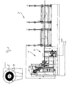
- the folded spiral tube system consists of a folded spiral tube machine 1, a separating device 2 and a pipe drain block 3, which is connected downstream of the folded spiral-tube machine are.
- the metal strip processed in the spiral folding tube machine becomes unwound from a tape roll 4, which is shown in a schematically illustrated reel 5 is saved.
- the unwound metal strip is profiled in a roller mill 6, in such a way that one edge is raised and the other edge with a Beads are provided, which then run onto a rotating sleeve in such a way that the bead overlaps the raised edge and both then by pressure rollers can be folded into a fold that the coiled metal band too connects a pipe.
- the folded spiral tube machine is of a known type and will therefore not explained in detail here.
- the devices carrying the pipe or the pipe sections, for example Rollers 9 can in the manner shown even on the smallest pipe diameter 9 ', as indicated by dashed lines, can be set.
- the through the Separating pipe sections are then removed from the pipe drain block 3 removed and handed over to a storage table, not shown.
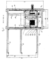
- the separation station 2 will now be described in more detail with reference to FIGS. 3 to 5.
- the base frame 10 are on the side Spars attached to each other parallel rails 12 on which a carriage 13 over Rolling is slidably guided, so that it is of different diameters can adjust the manufactured spiral duct.
- the carriage 13 In the set position the carriage 13 is fixed by a hand lever 14, through which an undercut Groove 15 of a beam connected to the cross bars of the frame 16 guided clamping piece is clamped to the carrier 16.
- the carriage 13 carries a table-like frame 20, on the table top 21 in parallel to the rails 12 extending guides are arranged on which a carriage 22 is guided back and forth.
- the carriage 22 is provided with guides 23 which run transversely to the rails 12.
- a displacement unit 24 is displaceably guided on the guides 23, which thus parallel to the axis of the tubes 7, 7 'via a synchronous motor 32 and a gearbox parallel to the pipe produced at the respective production speed can be moved.
- a cutter 26 which may be an end mill, with associated parts Drive motor 27 and gear unit and secondly the scissors 28 are held.
- the cutter 26 is driven by a three-phase motor 27, the speeds can have up to 25000 / min.
- the scissors 28 are a commercially available pair of scissors with two Tubular jacket 29 adjustable fork-shaped jaws 30 between the one Pipe jacket 29 penetrating cutting tongues 31, which with high frequency is driven swinging back and forth.
- the milling unit 26, 27 is connected to a socket 33 via a support piece 32.
- the scissors 28 are connected to the socket 35 via a holder 34.
- the sockets 33, 35 are independent of one another on linear guides by means of drive devices 36, 37 can be moved in the direction of the tube 7, 7 'and moved away from it.
- the milling cutter 26 and the scissors 28 can be passed through Moving the table-like frame 20 from the largest diameter of the tube 7 adjust to the smallest diameter of the tube 7 '.
- the separation device is controlled by a process computer, which Control data derived from the feed rate of the metal strip, which accordingly the optimal cutting speed of the milling cutter and the scissors is controlled.
- the separation of the pipe section from the pipe string in production basically takes place in the following steps:
- the production speed is down to 0, at least but reduced to a greatly reduced production speed.
- the pipe production is then resumed, so that the pipe rotates at a slow speed and is advanced.
- the cutter 26 moves in axial direction with pipe speed and cuts into the pipe jacket Circumferential slot that also cuts the fold.
- the milling cutter and the Scissors-carrying slides move in the axial direction synchronously with the tube With.
- the scissors are then switched on and move into the ones pre-cut by the milling cutter Slit in such a way that the tongue 31 the tube jacket penetrates and the jaws 30 from the outside put on the pipe jacket.
- the scissors are centered by this insertion into the slot.
- the pipe continues to run at slow speed, with the milling unit moving back and the scissors add the cut over the seam-free remaining tube circumference increased pipe speed and thus production speed.
- the pipe section held on the pipe drain stand is tipped over and then production of the spiral folding tube machine starts again.
Landscapes
- Engineering & Computer Science (AREA)
- Mechanical Engineering (AREA)
- Sawing (AREA)
- Shearing Machines (AREA)
Applications Claiming Priority (2)
| Application Number | Priority Date | Filing Date | Title |
|---|---|---|---|
| DE19944696A DE19944696A1 (de) | 1999-09-17 | 1999-09-17 | Vorrichtung zum Trennen von Rohren |
| DE19944696 | 1999-09-17 |
Publications (2)
| Publication Number | Publication Date |
|---|---|
| EP1099490A1 true EP1099490A1 (fr) | 2001-05-16 |
| EP1099490B1 EP1099490B1 (fr) | 2003-11-26 |
Family
ID=7922432
Family Applications (1)
| Application Number | Title | Priority Date | Filing Date |
|---|---|---|---|
| EP00119188A Expired - Lifetime EP1099490B1 (fr) | 1999-09-17 | 2000-09-05 | Dispositif pour couper des tubes |
Country Status (4)
| Country | Link |
|---|---|
| US (1) | US6619162B1 (fr) |
| EP (1) | EP1099490B1 (fr) |
| DE (2) | DE19944696A1 (fr) |
| DK (1) | DK1099490T3 (fr) |
Families Citing this family (3)
| Publication number | Priority date | Publication date | Assignee | Title |
|---|---|---|---|---|
| US8091455B2 (en) | 2008-01-30 | 2012-01-10 | Cummins Filtration Ip, Inc. | Apparatus, system, and method for cutting tubes |
| US8386289B2 (en) * | 2010-02-15 | 2013-02-26 | Accenture Global Services Limited | Multiple simultaneous session support by a remote technician |
| CN117680760B (zh) * | 2024-01-12 | 2026-03-31 | 衡阳鸿菱石油管材有限责任公司 | 一种无缝钢管轧制成型后的定长切割机 |
Citations (3)
| Publication number | Priority date | Publication date | Assignee | Title |
|---|---|---|---|---|
| US2547375A (en) * | 1946-12-30 | 1951-04-03 | Wiremold Co | Cutoff device for tubing |
| US5074018A (en) * | 1989-06-13 | 1991-12-24 | Emil Suter Maschinenfabrik Ag | Method and device for the cutting of pipes into separate pipe sections |
| EP0826467A1 (fr) * | 1996-08-30 | 1998-03-04 | S.I.C.A. SERRANDE INFISSI CARPENTERIA ATTREZZATURA S.p.A. | Procédé, dispositif et outil pour couper une barre tubulaire |
Family Cites Families (4)
| Publication number | Priority date | Publication date | Assignee | Title |
|---|---|---|---|---|
| US4362187A (en) * | 1980-08-05 | 1982-12-07 | Manville Service Corporation | Spirally-formed thermoplastic tube |
| US5239901A (en) * | 1992-09-11 | 1993-08-31 | Lin I Nan | CNC lathe |
| US5265505A (en) * | 1992-10-29 | 1993-11-30 | Frechette Eugene L | Turret-lathe coolant system |
| DE4342325C2 (de) * | 1993-12-11 | 1999-10-14 | Reika Werk Gmbh Maschf | Verfahren und Vorrichtung zum lage- und maßgenauen Anfasen eines Rohrendes |
-
1999
- 1999-09-17 DE DE19944696A patent/DE19944696A1/de not_active Withdrawn
-
2000
- 2000-09-05 DK DK00119188T patent/DK1099490T3/da active
- 2000-09-05 DE DE50004554T patent/DE50004554D1/de not_active Expired - Fee Related
- 2000-09-05 EP EP00119188A patent/EP1099490B1/fr not_active Expired - Lifetime
- 2000-09-18 US US09/664,327 patent/US6619162B1/en not_active Expired - Fee Related
Patent Citations (3)
| Publication number | Priority date | Publication date | Assignee | Title |
|---|---|---|---|---|
| US2547375A (en) * | 1946-12-30 | 1951-04-03 | Wiremold Co | Cutoff device for tubing |
| US5074018A (en) * | 1989-06-13 | 1991-12-24 | Emil Suter Maschinenfabrik Ag | Method and device for the cutting of pipes into separate pipe sections |
| EP0826467A1 (fr) * | 1996-08-30 | 1998-03-04 | S.I.C.A. SERRANDE INFISSI CARPENTERIA ATTREZZATURA S.p.A. | Procédé, dispositif et outil pour couper une barre tubulaire |
Also Published As
| Publication number | Publication date |
|---|---|
| DE50004554D1 (de) | 2004-01-08 |
| EP1099490B1 (fr) | 2003-11-26 |
| DE19944696A1 (de) | 2001-03-22 |
| DK1099490T3 (da) | 2004-03-29 |
| US6619162B1 (en) | 2003-09-16 |
Similar Documents
| Publication | Publication Date | Title |
|---|---|---|
| WO2015052339A1 (fr) | Dispositif de coupe à longueur de profilés en matière plastique extrudés | |
| DD149199A1 (de) | Vorrichtung zur bewerkstelligung eines fliegenden rollenwechsels | |
| DE2620190C3 (de) | Elektrische Widerstands-Stumpfschweißmaschine | |
| EP2803609B1 (fr) | Machine d'enroulement de matériaux en forme de bande | |
| EP1099490B1 (fr) | Dispositif pour couper des tubes | |
| DE69709388T2 (de) | Verfahren und vorrichtung zur herstellung von farbrollern | |
| DE2610289A1 (de) | Vorrichtung und verfahren zur herstellung und behandlung von metallbaendern | |
| DE60200291T2 (de) | Umwickelmaschine mit Flanken zum Tragen von sich entlang einer geschlossenen Bahn bewegenden greifenden Zentrierdornen | |
| DE3001230C2 (de) | Verfahren zum Spalten eines Bandes und Spaltanlage für Bänder | |
| DE2446776C2 (de) | Verfahren zur Herstellung einer geteilten Futtermutter für ein Bohrfutter | |
| EP0503363A1 (fr) | Dispositif de coupe et d'application de bandes dans une machine à enrouler | |
| DE2455902C3 (de) | Verfahren zur Herstellung von Tübbing- bzw. Tunnelausbausegmenten und Einrichtungen zur Durchführung des Verfahrens | |
| DE4001787C1 (fr) | ||
| EP0683032B1 (fr) | Dispositif pour la fabrication de conduits coaxiaux | |
| DE3219358A1 (de) | Einrichtung zum zerteilen von kontinuierlich vorgeschobenen rohren | |
| DE1286382B (de) | Vorrichtung zum Trennen und gleichzeitigen Bearbeiten der Trennkante eines in einem endlosen Strang kontinuierlich anfallenden Rohres | |
| DE102017126721A1 (de) | Verfahren und Vorrichtung zum Schneiden von Werkstücken aus Kunststoff | |
| DE60000888T2 (de) | Ein Verfahren und eine Vorrichtung zur kontinuierlichen Herstellung von Förderschnecken für Archimedesförderschnecken | |
| DE1690491B1 (de) | Vorrichtung zur kontinuierlichen herstellung eines koaxialkabels | |
| EP1964621B1 (fr) | Dispositif et procédé de fabrication de profilés | |
| EP3969236A1 (fr) | Dispositif et procédé de coupe en longueur d'un élément profilé en plastique | |
| DE102014116653A1 (de) | Wickelmaschine zum Wickeln von Warenbahnen | |
| EP0114613A1 (fr) | Tuyau flexible hélicoidal | |
| DE3116990A1 (de) | Maschine zur herstellung von schraubenfoermig gewickelten blechrohren | |
| DE69700206T2 (de) | Umreifungsmaschine für Bandmaterialrollen |
Legal Events
| Date | Code | Title | Description |
|---|---|---|---|
| PUAI | Public reference made under article 153(3) epc to a published international application that has entered the european phase |
Free format text: ORIGINAL CODE: 0009012 |
|
| AK | Designated contracting states |
Kind code of ref document: A1 Designated state(s): CH DE DK FR GB IT LI |
|
| AX | Request for extension of the european patent |
Free format text: AL;LT;LV;MK;RO;SI |
|
| 17P | Request for examination filed |
Effective date: 20011114 |
|
| AKX | Designation fees paid |
Free format text: CH DE DK FR GB IT LI |
|
| GRAH | Despatch of communication of intention to grant a patent |
Free format text: ORIGINAL CODE: EPIDOS IGRA |
|
| GRAS | Grant fee paid |
Free format text: ORIGINAL CODE: EPIDOSNIGR3 |
|
| GRAA | (expected) grant |
Free format text: ORIGINAL CODE: 0009210 |
|
| AK | Designated contracting states |
Kind code of ref document: B1 Designated state(s): CH DE DK FR GB IT LI |
|
| REG | Reference to a national code |
Ref country code: GB Ref legal event code: FG4D Free format text: NOT ENGLISH |
|
| REG | Reference to a national code |
Ref country code: CH Ref legal event code: EP |
|
| REG | Reference to a national code |
Ref country code: CH Ref legal event code: NV Representative=s name: BOVARD AG PATENTANWAELTE |
|
| REF | Corresponds to: |
Ref document number: 50004554 Country of ref document: DE Date of ref document: 20040108 Kind code of ref document: P |
|
| GBT | Gb: translation of ep patent filed (gb section 77(6)(a)/1977) |
Effective date: 20040216 |
|
| REG | Reference to a national code |
Ref country code: DK Ref legal event code: T3 |
|
| ET | Fr: translation filed | ||
| PG25 | Lapsed in a contracting state [announced via postgrant information from national office to epo] |
Ref country code: GB Free format text: LAPSE BECAUSE OF NON-PAYMENT OF DUE FEES Effective date: 20040905 |
|
| PG25 | Lapsed in a contracting state [announced via postgrant information from national office to epo] |
Ref country code: LI Free format text: LAPSE BECAUSE OF NON-PAYMENT OF DUE FEES Effective date: 20040930 Ref country code: DK Free format text: LAPSE BECAUSE OF NON-PAYMENT OF DUE FEES Effective date: 20040930 Ref country code: CH Free format text: LAPSE BECAUSE OF NON-PAYMENT OF DUE FEES Effective date: 20040930 |
|
| PLBE | No opposition filed within time limit |
Free format text: ORIGINAL CODE: 0009261 |
|
| STAA | Information on the status of an ep patent application or granted ep patent |
Free format text: STATUS: NO OPPOSITION FILED WITHIN TIME LIMIT |
|
| 26N | No opposition filed |
Effective date: 20040827 |
|
| PG25 | Lapsed in a contracting state [announced via postgrant information from national office to epo] |
Ref country code: DE Free format text: LAPSE BECAUSE OF NON-PAYMENT OF DUE FEES Effective date: 20050401 |
|
| GBPC | Gb: european patent ceased through non-payment of renewal fee |
Effective date: 20040905 |
|
| REG | Reference to a national code |
Ref country code: CH Ref legal event code: PL |
|
| PG25 | Lapsed in a contracting state [announced via postgrant information from national office to epo] |
Ref country code: FR Free format text: LAPSE BECAUSE OF NON-PAYMENT OF DUE FEES Effective date: 20050531 |
|
| REG | Reference to a national code |
Ref country code: DK Ref legal event code: EBP |
|
| REG | Reference to a national code |
Ref country code: FR Ref legal event code: ST |
|
| PG25 | Lapsed in a contracting state [announced via postgrant information from national office to epo] |
Ref country code: IT Free format text: LAPSE BECAUSE OF NON-PAYMENT OF DUE FEES Effective date: 20050905 |