EP1099492A2 - Automatisierten Bohrmechanismus zum Formen von Aushalsungen - Google Patents
Automatisierten Bohrmechanismus zum Formen von Aushalsungen Download PDFInfo
- Publication number
- EP1099492A2 EP1099492A2 EP00660196A EP00660196A EP1099492A2 EP 1099492 A2 EP1099492 A2 EP 1099492A2 EP 00660196 A EP00660196 A EP 00660196A EP 00660196 A EP00660196 A EP 00660196A EP 1099492 A2 EP1099492 A2 EP 1099492A2
- Authority
- EP
- European Patent Office
- Prior art keywords
- piston
- collar
- set forth
- tool head
- drive shaft
- Prior art date
- Legal status (The legal status is an assumption and is not a legal conclusion. Google has not performed a legal analysis and makes no representation as to the accuracy of the status listed.)
- Granted
Links
Images

Classifications
-
- B—PERFORMING OPERATIONS; TRANSPORTING
- B23—MACHINE TOOLS; METAL-WORKING NOT OTHERWISE PROVIDED FOR
- B23B—TURNING; BORING
- B23B41/00—Boring or drilling machines or devices specially adapted for particular work; Accessories specially adapted therefor
-
- B—PERFORMING OPERATIONS; TRANSPORTING
- B21—MECHANICAL METAL-WORKING WITHOUT ESSENTIALLY REMOVING MATERIAL; PUNCHING METAL
- B21J—FORGING; HAMMERING; PRESSING METAL; RIVETING; FORGE FURNACES
- B21J5/00—Methods for forging, hammering, or pressing; Special equipment or accessories therefor
- B21J5/06—Methods for forging, hammering, or pressing; Special equipment or accessories therefor for performing particular operations
- B21J5/063—Friction heat forging
- B21J5/066—Flow drilling
-
- B—PERFORMING OPERATIONS; TRANSPORTING
- B21—MECHANICAL METAL-WORKING WITHOUT ESSENTIALLY REMOVING MATERIAL; PUNCHING METAL
- B21C—MANUFACTURE OF METAL SHEETS, WIRE, RODS, TUBES, PROFILES OR LIKE SEMI-MANUFACTURED PRODUCTS OTHERWISE THAN BY ROLLING; AUXILIARY OPERATIONS USED IN CONNECTION WITH METAL-WORKING WITHOUT ESSENTIALLY REMOVING MATERIAL
- B21C37/00—Manufacture of metal sheets, rods, wire, tubes, profiles or like semi-manufactured products, not otherwise provided for; Manufacture of tubes of special shape
- B21C37/06—Manufacture of metal sheets, rods, wire, tubes, profiles or like semi-manufactured products, not otherwise provided for; Manufacture of tubes of special shape of tubes or metal hoses; Combined procedures for making tubes, e.g. for making multi-wall tubes
- B21C37/15—Making tubes of special shape; Making tube fittings
- B21C37/28—Making tube fittings for connecting pipes, e.g. U-pieces
- B21C37/29—Making branched pieces, e.g. T-pieces
- B21C37/298—Forming collars by flow-drilling
Definitions
- the invention relates to an automated collar-forming drill mechanism, comprising a rotatable drive shaft, a tool head mounted on the end of the drive shaft, an actuator for rotating the drive shaft, transfer means for carrying the drive shaft and the tool head back and forth in axial direction, said tool head comprising a drill for drilling a hole in the wall of a workpiece, such as a pipe, as the tool head is carried in one axial direction during a drilling operation, and collar-forming pegs adapted to extend below the hole rims and to extract the hole-encircling wall material for a collar as the tool head is carried in the opposite axial direction during a collar-forming operation.
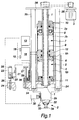
- a drive shaft 1 to be rotated by an actuator 3 is fitted with a tool head 2, comprising conventionally a drill bit 34 and collar-forming pegs 33, which engage in slots present in the conical surface of an adjusting means 32 in such a way that, by rotating the adjusting means 32 relative to the rod of the drill 34, the collar-forming pegs 33 can be extended from the drill bit or retracted into the drill bit, depending on the rotational direction of the adjusting means 32.
- the arrangement can be conventionally such that a spiral spring keeps the adjusting cone 32 in a position with the pegs 33 retracted but, by decelerating the rotation of the adjusting cone 32 by means of a brake 31 operated by a pneumatic cylinder 30, the pegs 33 can be extended for the duration of braking.
- the braking force only needs to overcome the springback factor of a spiral spring (not shown).
- the tool head 2 and the drive shaft 1 are maneuvered back and forth in axial direction, in practice up and down, by means of a piston-cylinder assembly 5-9, comprising two cylinders 5, 7, the lower cylinder 5 of which constitutes at the same time a housing 4, which is braced to be immobile.
- Each cylinder carries a piston 6, 8, on one side of which is provided a hydraulic fluid compartment 5h and 7h, respectively, and on the other side there is a cylinder compartment 5p, 7p for a pneumatic gas.
- a reversing valve 14 fig. 2
- the pistons 6, 8 and the piston rod 9 travel up or down as a result of pressure coming from a source of compressed air 15. Control over operating speeds and operating ranges is effected as follows.
- the hydraulic fluid compartments 5h, 7h are in a flow communication with each other by way of a flow channel 18c (fig. 2) provided with oppositely facing directional control valves 17 and, alongside the same, individually adjustable throttle valves 18a, 18b.
- Manual adjusting knobs 16 for the throttle valves are visible in fig. 1 along with a hydraulic valve block 16.
- the throttle valves 8a, 8b are adapted to be by-passed by a hydraulic on/off valve 20, in the on-position of which the tool head is drivable with said rapid actions.
- the hydraulic valve 20 receives its control from a pneumatic impulse valve 21, the impulse output threshold of which determines the initial position of a drilling operation and the terminal position of a collar-forming operation.
- a flange 24 movable along with the tool head 2 is fitted with an impulse output threshold barrier 23, 26, whose position is vertically adjustable by means of a screw spindle 25.
- the pneumatic impulse valve 21 has its roller 22 running along the outer threshold barrier surface 23, the hydraulic valve 20 will be in its on-position, allowing an unimpeded circulation of hydraulic fluid between the cylinder compartments 5h, 7h, whereby the pneumatic cylinders 5p, 7p are capable of driving the piston rod 9 up or down with a high-speed action.
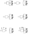
- the condition of fig. 1 corresponds to the initial condition shown in fig. 3A, wherein the roller 22 is in its extreme bottom position with respect to the impulse output threshold barrier 23, 25, 26 (which, in turn, is set in its top position).
- a bottom barrier 27 collides with a flange 28 of the housing 4 and in so doing closes a port 29 associated with the pneumatic circuit.
- This closure delivers a pneumatic compressed-air pulse to a pneumatic block 13, as a result of which the reversing valve 14 reverses its direction for the commencement of a collar-forming operation (figs. 4A and 4B).
- the bottom barrier 27 sets also mechanically the bottom limit for a drilling operation exactly at a certain point, which eliminates inaccuracy of the pneumatically effected operations.
- the bottom barrier 27 has also its distance from the flange 28 adjustable by means of a screw tap, which attaches the barrier 27 to the flange 24.
- a pressure impulse produced by closing the port 29 delivers the pressure also to a brake cylinder 30, which concurrently with a reversal extends the collar-forming pegs 33 while the adjusting cone 32 is rotated around a drill rod 1a by a friction brake 31.
- the valve 21 has its roller 22 collide again with the conical surface 26 of the threshold barrier 23 and shift the valve 21 to a position, wherein the compressed air is able to pass through the valve 21 for pushing the valve 20 to the on-position, allowing an unimpeded circulation of hydraulic fluid between the cylinder compartments 5h, 7h, whereby the tool head 2 rises up with a high-speed action (Fig. 4C).
- An impulse threshold valve (not shown), setting the top position, drives the reversing valve 14 to an intermediate position and the pistons 6, 8 come to a halt.
- the next run is commenced either with manual control or automatically by delivering a control impulse to the reversing valve 14, which is driven to the top position (fig. 2 shows the same in bottom position).
- the impulse threshold valve, setting the top position may also have a threshold response or barrier which is adjustable in order to eliminate an unnecessary travel from the high-speed action.
- a flange 24 which is movable along with the piston rod 9 and fitted with a journal box 2a for the tool head 2, with the bottom barrier 27, and with the impulse output threshold barrier 23, 25, 26 for the valve 21.
- the movable flange 24 is fitted with guide bars 35 extending through the housing 4, the top ends of which are secured to a bearing flange 36 the same as the piston rod 9.
- the actuator 3 is also secured to the bearing flange 36.
Landscapes
- Engineering & Computer Science (AREA)
- Mechanical Engineering (AREA)
- Earth Drilling (AREA)
- Drilling And Boring (AREA)
- Farming Of Fish And Shellfish (AREA)
- Perforating, Stamping-Out Or Severing By Means Other Than Cutting (AREA)
- Actuator (AREA)
Applications Claiming Priority (2)
| Application Number | Priority Date | Filing Date | Title |
|---|---|---|---|
| FI992437A FI108997B (fi) | 1999-11-12 | 1999-11-12 | Automaattinen kaulustusporalaite |
| FI992437 | 1999-11-12 |
Publications (3)
| Publication Number | Publication Date |
|---|---|
| EP1099492A2 true EP1099492A2 (de) | 2001-05-16 |
| EP1099492A3 EP1099492A3 (de) | 2002-02-06 |
| EP1099492B1 EP1099492B1 (de) | 2005-03-30 |
Family
ID=8555591
Family Applications (1)
| Application Number | Title | Priority Date | Filing Date |
|---|---|---|---|
| EP00660196A Expired - Lifetime EP1099492B1 (de) | 1999-11-12 | 2000-11-09 | Automatisierten Bohrmechanismus zum Formen von Aushalsungen |
Country Status (8)
| Country | Link |
|---|---|
| US (1) | US6427508B1 (de) |
| EP (1) | EP1099492B1 (de) |
| JP (1) | JP2001182715A (de) |
| KR (1) | KR20010070198A (de) |
| AT (1) | ATE291971T1 (de) |
| DE (1) | DE60019064D1 (de) |
| FI (1) | FI108997B (de) |
| MX (1) | MXPA00011065A (de) |
Cited By (5)
| Publication number | Priority date | Publication date | Assignee | Title |
|---|---|---|---|---|
| EP1415623A1 (de) | 2002-10-16 | 2004-05-06 | Advanced Medical Technologies AG | Implantat für die Anordnung zwischen Wirbeln der Wirbelsäule |
| CN102151851A (zh) * | 2011-04-25 | 2011-08-17 | 林雄 | 气动推力电主轴 |
| CN103240445A (zh) * | 2013-05-19 | 2013-08-14 | 交通运输部北海救助局 | 针对遇险翻扣船舶的应急救助快速防爆开孔设备 |
| CN109108324A (zh) * | 2017-06-22 | 2019-01-01 | 帕斯冲压技术股份公司 | 钻孔工具和钻孔工具的操作方法 |
| US11415031B2 (en) | 2017-07-21 | 2022-08-16 | Bosal Emission Control Systems Nv | Method for forming a collar in a muffler housing |
Families Citing this family (9)
| Publication number | Priority date | Publication date | Assignee | Title |
|---|---|---|---|---|
| US7003995B2 (en) * | 2004-03-12 | 2006-02-28 | General Motors Corporation | Hydrotapping power unit |
| US7284406B2 (en) * | 2005-05-02 | 2007-10-23 | Robert Krauss | Tube end forming and coping method and apparatus |
| US8690128B1 (en) * | 2008-07-23 | 2014-04-08 | Lippert Components Manufacturing, Inc. | Hydraulic leveling cylinder |
| DE102009052482A1 (de) * | 2009-02-11 | 2010-08-19 | Sms Meer Gmbh | Verfahren und Vorrichtung zur Herstellung von rohrförmigen Werkstücken aus einen vorgelochten Hohlblock |
| TWM367763U (en) * | 2009-06-15 | 2009-11-01 | Mao-Lian Huang | Processing device of Metal housing |
| CN102151877B (zh) * | 2011-03-16 | 2012-08-22 | 杭州田林机械制造有限公司 | 新型钻床传动机构 |
| CN102744444A (zh) * | 2012-07-20 | 2012-10-24 | 詹高峰 | 一种气电型动力头装置 |
| CN102744443A (zh) * | 2012-07-20 | 2012-10-24 | 詹高峰 | 气电型动力头 |
| CN112692109B (zh) * | 2020-12-25 | 2025-03-18 | 天津鑫凯建业科技有限公司 | 一种金刚石薄壁钻头基体校圆装置 |
Family Cites Families (7)
| Publication number | Priority date | Publication date | Assignee | Title |
|---|---|---|---|---|
| NL302693A (de) * | 1900-01-01 | |||
| US2631480A (en) * | 1951-03-05 | 1953-03-17 | Charles Leitschuh | Hydraulic step drilling unit |
| FI58879C (fi) * | 1973-05-30 | 1981-05-11 | Leo Larikka | Automatisk flaensborranordning |
| NL7700871A (nl) * | 1977-01-27 | 1978-07-31 | Geffen Tech Adviesbureau Bv | Werkwijze en inrichting voor het door wrij- vingswarmte en druk maken van een door een kraag omgeven gat in metalen plaat of de wand van een metalen buis. |
| FI800280A7 (fi) * | 1980-01-30 | 1981-01-01 | Serlachius Oy | Kaulustusporalaite. |
| US5205149A (en) * | 1991-09-11 | 1993-04-27 | Amada Mfg. America Inc. | Press machine having adjustable striker |
| US5209094A (en) * | 1992-03-06 | 1993-05-11 | B & G Manufacturing Co. | Chamfer and stamp machine |
-
1999
- 1999-11-12 FI FI992437A patent/FI108997B/fi active
-
2000
- 2000-11-07 JP JP2000339566A patent/JP2001182715A/ja active Pending
- 2000-11-09 DE DE60019064T patent/DE60019064D1/de not_active Expired - Lifetime
- 2000-11-09 EP EP00660196A patent/EP1099492B1/de not_active Expired - Lifetime
- 2000-11-09 KR KR1020000066339A patent/KR20010070198A/ko not_active Withdrawn
- 2000-11-09 AT AT00660196T patent/ATE291971T1/de not_active IP Right Cessation
- 2000-11-10 US US09/710,511 patent/US6427508B1/en not_active Expired - Lifetime
- 2000-11-10 MX MXPA00011065A patent/MXPA00011065A/es unknown
Cited By (7)
| Publication number | Priority date | Publication date | Assignee | Title |
|---|---|---|---|---|
| EP1415623A1 (de) | 2002-10-16 | 2004-05-06 | Advanced Medical Technologies AG | Implantat für die Anordnung zwischen Wirbeln der Wirbelsäule |
| CN102151851A (zh) * | 2011-04-25 | 2011-08-17 | 林雄 | 气动推力电主轴 |
| CN102151851B (zh) * | 2011-04-25 | 2012-11-21 | 林雄 | 气动推力电主轴 |
| CN103240445A (zh) * | 2013-05-19 | 2013-08-14 | 交通运输部北海救助局 | 针对遇险翻扣船舶的应急救助快速防爆开孔设备 |
| CN103240445B (zh) * | 2013-05-19 | 2015-02-04 | 交通运输部北海救助局 | 针对遇险翻扣船舶的应急救助快速防爆开孔设备 |
| CN109108324A (zh) * | 2017-06-22 | 2019-01-01 | 帕斯冲压技术股份公司 | 钻孔工具和钻孔工具的操作方法 |
| US11415031B2 (en) | 2017-07-21 | 2022-08-16 | Bosal Emission Control Systems Nv | Method for forming a collar in a muffler housing |
Also Published As
| Publication number | Publication date |
|---|---|
| EP1099492B1 (de) | 2005-03-30 |
| FI108997B (fi) | 2002-05-15 |
| ATE291971T1 (de) | 2005-04-15 |
| MXPA00011065A (es) | 2003-06-19 |
| EP1099492A3 (de) | 2002-02-06 |
| JP2001182715A (ja) | 2001-07-06 |
| KR20010070198A (ko) | 2001-07-25 |
| DE60019064D1 (de) | 2005-05-04 |
| FI19992437L (fi) | 2001-05-13 |
| US6427508B1 (en) | 2002-08-06 |
Similar Documents
| Publication | Publication Date | Title |
|---|---|---|
| EP1099492B1 (de) | Automatisierten Bohrmechanismus zum Formen von Aushalsungen | |
| CN101239459B (zh) | 具有气动的冲击装置的手持式工具机 | |
| US4355691A (en) | Hydraulic drilling apparatus | |
| US5816091A (en) | Wire shaping apparatus, in particular universal spring winding machine, with cutting device | |
| DE2029512C3 (de) | Schlagwerkzeug | |
| DE2832169A1 (de) | Motorisch betriebener bohrhammer | |
| US4936156A (en) | Mechanical transmission shifting mechanism | |
| CN102741017A (zh) | 用于润滑钻岩机的钻柄的方法和设备 | |
| DE1652685C3 (de) | Einrichtung zum Umschalten von Schlagbohren auf Drehbohren | |
| EP2960374A1 (de) | Arbeitsgerät mit stampfwerk oder schlagwerk mit verschränktem kurbeltrieb | |
| US3307638A (en) | Rock drill drive | |
| US20200248725A1 (en) | Oscillation cylinder arrangement | |
| EP2017039A2 (de) | Handwerkzeugmaschine mit Schlagwerk | |
| EP0168382B1 (de) | Einrichtung zum schlagenden und/oder drehenden Bohren | |
| CN106335031A (zh) | 电锤 | |
| DE3932134A1 (de) | Hammer mit luftfederschlagwerk | |
| US3802517A (en) | Screwdrivers and like tools | |
| SE456595B (sv) | Med slagverkan arbetande kompressionsvakuummaskin | |
| DE4020776C2 (de) | ||
| EP0894982B1 (de) | Hydraulische Servoeinrichtung | |
| CN102482917B (zh) | 冲击钻设备 | |
| CN116393923B (zh) | 一种球阀的加工工艺及球阀 | |
| JPS5914395B2 (ja) | 可変ピツチプロペラの羽根用調整装置 | |
| CN208068604U (zh) | 加工机的超音波刀把控制装置 | |
| EP0890028B1 (de) | Verfahren zum betreiben einer werkzeugmaschine |
Legal Events
| Date | Code | Title | Description |
|---|---|---|---|
| PUAI | Public reference made under article 153(3) epc to a published international application that has entered the european phase |
Free format text: ORIGINAL CODE: 0009012 |
|
| AK | Designated contracting states |
Kind code of ref document: A2 Designated state(s): AT BE CH CY DE DK ES FI FR GB GR IE IT LI LU MC NL PT SE TR |
|
| AX | Request for extension of the european patent |
Free format text: AL;LT;LV;MK;RO;SI |
|
| PUAL | Search report despatched |
Free format text: ORIGINAL CODE: 0009013 |
|
| AK | Designated contracting states |
Kind code of ref document: A3 Designated state(s): AT BE CH CY DE DK ES FI FR GB GR IE IT LI LU MC NL PT SE TR |
|
| AX | Request for extension of the european patent |
Free format text: AL;LT;LV;MK;RO;SI |
|
| 17P | Request for examination filed |
Effective date: 20020806 |
|
| AKX | Designation fees paid |
Free format text: AT BE CH CY DE DK ES FI FR GB GR IE IT LI LU MC NL PT SE TR |
|
| 17Q | First examination report despatched |
Effective date: 20040330 |
|
| GRAP | Despatch of communication of intention to grant a patent |
Free format text: ORIGINAL CODE: EPIDOSNIGR1 |
|
| RIN1 | Information on inventor provided before grant (corrected) |
Inventor name: ROPPONEN, VESA Inventor name: LETHO, PERTTI Inventor name: HAAVISTO, KARI Inventor name: SAARI, TIMO |
|
| GRAS | Grant fee paid |
Free format text: ORIGINAL CODE: EPIDOSNIGR3 |
|
| GRAA | (expected) grant |
Free format text: ORIGINAL CODE: 0009210 |
|
| AK | Designated contracting states |
Kind code of ref document: B1 Designated state(s): AT BE CH CY DE DK ES FI FR GB GR IE IT LI LU MC NL PT SE TR |
|
| PG25 | Lapsed in a contracting state [announced via postgrant information from national office to epo] |
Ref country code: IT Free format text: LAPSE BECAUSE OF FAILURE TO SUBMIT A TRANSLATION OF THE DESCRIPTION OR TO PAY THE FEE WITHIN THE PRESCRIBED TIME-LIMIT;WARNING: LAPSES OF ITALIAN PATENTS WITH EFFECTIVE DATE BEFORE 2007 MAY HAVE OCCURRED AT ANY TIME BEFORE 2007. THE CORRECT EFFECTIVE DATE MAY BE DIFFERENT FROM THE ONE RECORDED. Effective date: 20050330 Ref country code: LI Free format text: LAPSE BECAUSE OF FAILURE TO SUBMIT A TRANSLATION OF THE DESCRIPTION OR TO PAY THE FEE WITHIN THE PRESCRIBED TIME-LIMIT Effective date: 20050330 Ref country code: AT Free format text: LAPSE BECAUSE OF FAILURE TO SUBMIT A TRANSLATION OF THE DESCRIPTION OR TO PAY THE FEE WITHIN THE PRESCRIBED TIME-LIMIT Effective date: 20050330 Ref country code: NL Free format text: LAPSE BECAUSE OF FAILURE TO SUBMIT A TRANSLATION OF THE DESCRIPTION OR TO PAY THE FEE WITHIN THE PRESCRIBED TIME-LIMIT Effective date: 20050330 Ref country code: TR Free format text: LAPSE BECAUSE OF FAILURE TO SUBMIT A TRANSLATION OF THE DESCRIPTION OR TO PAY THE FEE WITHIN THE PRESCRIBED TIME-LIMIT Effective date: 20050330 Ref country code: BE Free format text: LAPSE BECAUSE OF FAILURE TO SUBMIT A TRANSLATION OF THE DESCRIPTION OR TO PAY THE FEE WITHIN THE PRESCRIBED TIME-LIMIT Effective date: 20050330 Ref country code: FI Free format text: LAPSE BECAUSE OF FAILURE TO SUBMIT A TRANSLATION OF THE DESCRIPTION OR TO PAY THE FEE WITHIN THE PRESCRIBED TIME-LIMIT Effective date: 20050330 Ref country code: CH Free format text: LAPSE BECAUSE OF FAILURE TO SUBMIT A TRANSLATION OF THE DESCRIPTION OR TO PAY THE FEE WITHIN THE PRESCRIBED TIME-LIMIT Effective date: 20050330 |
|
| REG | Reference to a national code |
Ref country code: GB Ref legal event code: FG4D |
|
| REG | Reference to a national code |
Ref country code: CH Ref legal event code: EP |
|
| REF | Corresponds to: |
Ref document number: 60019064 Country of ref document: DE Date of ref document: 20050504 Kind code of ref document: P |
|
| REG | Reference to a national code |
Ref country code: IE Ref legal event code: FG4D |
|
| PG25 | Lapsed in a contracting state [announced via postgrant information from national office to epo] |
Ref country code: GR Free format text: LAPSE BECAUSE OF FAILURE TO SUBMIT A TRANSLATION OF THE DESCRIPTION OR TO PAY THE FEE WITHIN THE PRESCRIBED TIME-LIMIT Effective date: 20050630 Ref country code: DK Free format text: LAPSE BECAUSE OF FAILURE TO SUBMIT A TRANSLATION OF THE DESCRIPTION OR TO PAY THE FEE WITHIN THE PRESCRIBED TIME-LIMIT Effective date: 20050630 |
|
| PG25 | Lapsed in a contracting state [announced via postgrant information from national office to epo] |
Ref country code: DE Free format text: LAPSE BECAUSE OF FAILURE TO SUBMIT A TRANSLATION OF THE DESCRIPTION OR TO PAY THE FEE WITHIN THE PRESCRIBED TIME-LIMIT Effective date: 20050701 |
|
| PG25 | Lapsed in a contracting state [announced via postgrant information from national office to epo] |
Ref country code: ES Free format text: LAPSE BECAUSE OF FAILURE TO SUBMIT A TRANSLATION OF THE DESCRIPTION OR TO PAY THE FEE WITHIN THE PRESCRIBED TIME-LIMIT Effective date: 20050711 |
|
| PG25 | Lapsed in a contracting state [announced via postgrant information from national office to epo] |
Ref country code: PT Free format text: LAPSE BECAUSE OF FAILURE TO SUBMIT A TRANSLATION OF THE DESCRIPTION OR TO PAY THE FEE WITHIN THE PRESCRIBED TIME-LIMIT Effective date: 20050907 |
|
| REG | Reference to a national code |
Ref country code: CH Ref legal event code: PL |
|
| NLV1 | Nl: lapsed or annulled due to failure to fulfill the requirements of art. 29p and 29m of the patents act | ||
| PG25 | Lapsed in a contracting state [announced via postgrant information from national office to epo] |
Ref country code: CY Free format text: LAPSE BECAUSE OF FAILURE TO SUBMIT A TRANSLATION OF THE DESCRIPTION OR TO PAY THE FEE WITHIN THE PRESCRIBED TIME-LIMIT Effective date: 20051109 Ref country code: IE Free format text: LAPSE BECAUSE OF NON-PAYMENT OF DUE FEES Effective date: 20051109 Ref country code: GB Free format text: LAPSE BECAUSE OF NON-PAYMENT OF DUE FEES Effective date: 20051109 |
|
| PG25 | Lapsed in a contracting state [announced via postgrant information from national office to epo] |
Ref country code: MC Free format text: LAPSE BECAUSE OF NON-PAYMENT OF DUE FEES Effective date: 20051130 Ref country code: LU Free format text: LAPSE BECAUSE OF NON-PAYMENT OF DUE FEES Effective date: 20051130 |
|
| PLBE | No opposition filed within time limit |
Free format text: ORIGINAL CODE: 0009261 |
|
| STAA | Information on the status of an ep patent application or granted ep patent |
Free format text: STATUS: NO OPPOSITION FILED WITHIN TIME LIMIT |
|
| 26N | No opposition filed |
Effective date: 20060102 |
|
| EN | Fr: translation not filed | ||
| GBPC | Gb: european patent ceased through non-payment of renewal fee |
Effective date: 20051109 |
|
| REG | Reference to a national code |
Ref country code: IE Ref legal event code: MM4A |
|
| PG25 | Lapsed in a contracting state [announced via postgrant information from national office to epo] |
Ref country code: SE Free format text: LAPSE BECAUSE OF FAILURE TO SUBMIT A TRANSLATION OF THE DESCRIPTION OR TO PAY THE FEE WITHIN THE PRESCRIBED TIME-LIMIT Effective date: 20050630 |
|
| PG25 | Lapsed in a contracting state [announced via postgrant information from national office to epo] |
Ref country code: FR Free format text: LAPSE BECAUSE OF NON-PAYMENT OF DUE FEES Effective date: 20051130 |
|
| PG25 | Lapsed in a contracting state [announced via postgrant information from national office to epo] |
Ref country code: FR Free format text: LAPSE BECAUSE OF NON-PAYMENT OF DUE FEES Effective date: 20050330 |