EP1099528A2 - Dispositif et procédé pour fabriquer, des profilés en resine synthétique renforcés de fibres continues - Google Patents
Dispositif et procédé pour fabriquer, des profilés en resine synthétique renforcés de fibres continues Download PDFInfo
- Publication number
- EP1099528A2 EP1099528A2 EP00203872A EP00203872A EP1099528A2 EP 1099528 A2 EP1099528 A2 EP 1099528A2 EP 00203872 A EP00203872 A EP 00203872A EP 00203872 A EP00203872 A EP 00203872A EP 1099528 A2 EP1099528 A2 EP 1099528A2
- Authority
- EP
- European Patent Office
- Prior art keywords
- channel
- extrusion
- synthetic resin
- fibres
- fluid material
- Prior art date
- Legal status (The legal status is an assumption and is not a legal conclusion. Google has not performed a legal analysis and makes no representation as to the accuracy of the status listed.)
- Withdrawn
Links
Images


Classifications
-
- B—PERFORMING OPERATIONS; TRANSPORTING
- B29—WORKING OF PLASTICS; WORKING OF SUBSTANCES IN A PLASTIC STATE IN GENERAL
- B29C—SHAPING OR JOINING OF PLASTICS; SHAPING OF MATERIAL IN A PLASTIC STATE, NOT OTHERWISE PROVIDED FOR; AFTER-TREATMENT OF THE SHAPED PRODUCTS, e.g. REPAIRING
- B29C48/00—Extrusion moulding, i.e. expressing the moulding material through a die or nozzle which imparts the desired form; Apparatus therefor
- B29C48/25—Component parts, details or accessories; Auxiliary operations
- B29C48/30—Extrusion nozzles or dies
- B29C48/32—Extrusion nozzles or dies with annular openings, e.g. for forming tubular articles
- B29C48/34—Cross-head annular extrusion nozzles, i.e. for simultaneously receiving moulding material and the preform to be coated
-
- B—PERFORMING OPERATIONS; TRANSPORTING
- B29—WORKING OF PLASTICS; WORKING OF SUBSTANCES IN A PLASTIC STATE IN GENERAL
- B29C—SHAPING OR JOINING OF PLASTICS; SHAPING OF MATERIAL IN A PLASTIC STATE, NOT OTHERWISE PROVIDED FOR; AFTER-TREATMENT OF THE SHAPED PRODUCTS, e.g. REPAIRING
- B29C48/00—Extrusion moulding, i.e. expressing the moulding material through a die or nozzle which imparts the desired form; Apparatus therefor
- B29C48/022—Extrusion moulding, i.e. expressing the moulding material through a die or nozzle which imparts the desired form; Apparatus therefor characterised by the choice of material
-
- B—PERFORMING OPERATIONS; TRANSPORTING
- B29—WORKING OF PLASTICS; WORKING OF SUBSTANCES IN A PLASTIC STATE IN GENERAL
- B29C—SHAPING OR JOINING OF PLASTICS; SHAPING OF MATERIAL IN A PLASTIC STATE, NOT OTHERWISE PROVIDED FOR; AFTER-TREATMENT OF THE SHAPED PRODUCTS, e.g. REPAIRING
- B29C48/00—Extrusion moulding, i.e. expressing the moulding material through a die or nozzle which imparts the desired form; Apparatus therefor
- B29C48/03—Extrusion moulding, i.e. expressing the moulding material through a die or nozzle which imparts the desired form; Apparatus therefor characterised by the shape of the extruded material at extrusion
- B29C48/09—Articles with cross-sections having partially or fully enclosed cavities, e.g. pipes or channels
-
- B—PERFORMING OPERATIONS; TRANSPORTING
- B29—WORKING OF PLASTICS; WORKING OF SUBSTANCES IN A PLASTIC STATE IN GENERAL
- B29C—SHAPING OR JOINING OF PLASTICS; SHAPING OF MATERIAL IN A PLASTIC STATE, NOT OTHERWISE PROVIDED FOR; AFTER-TREATMENT OF THE SHAPED PRODUCTS, e.g. REPAIRING
- B29C48/00—Extrusion moulding, i.e. expressing the moulding material through a die or nozzle which imparts the desired form; Apparatus therefor
- B29C48/15—Extrusion moulding, i.e. expressing the moulding material through a die or nozzle which imparts the desired form; Apparatus therefor incorporating preformed parts or layers, e.g. extrusion moulding around inserts
- B29C48/156—Coating two or more articles simultaneously
-
- B—PERFORMING OPERATIONS; TRANSPORTING
- B29—WORKING OF PLASTICS; WORKING OF SUBSTANCES IN A PLASTIC STATE IN GENERAL
- B29C—SHAPING OR JOINING OF PLASTICS; SHAPING OF MATERIAL IN A PLASTIC STATE, NOT OTHERWISE PROVIDED FOR; AFTER-TREATMENT OF THE SHAPED PRODUCTS, e.g. REPAIRING
- B29C48/00—Extrusion moulding, i.e. expressing the moulding material through a die or nozzle which imparts the desired form; Apparatus therefor
- B29C48/03—Extrusion moulding, i.e. expressing the moulding material through a die or nozzle which imparts the desired form; Apparatus therefor characterised by the shape of the extruded material at extrusion
- B29C48/06—Rod-shaped
-
- B—PERFORMING OPERATIONS; TRANSPORTING
- B29—WORKING OF PLASTICS; WORKING OF SUBSTANCES IN A PLASTIC STATE IN GENERAL
- B29C—SHAPING OR JOINING OF PLASTICS; SHAPING OF MATERIAL IN A PLASTIC STATE, NOT OTHERWISE PROVIDED FOR; AFTER-TREATMENT OF THE SHAPED PRODUCTS, e.g. REPAIRING
- B29C48/00—Extrusion moulding, i.e. expressing the moulding material through a die or nozzle which imparts the desired form; Apparatus therefor
- B29C48/03—Extrusion moulding, i.e. expressing the moulding material through a die or nozzle which imparts the desired form; Apparatus therefor characterised by the shape of the extruded material at extrusion
- B29C48/12—Articles with an irregular circumference when viewed in cross-section, e.g. window profiles
-
- B—PERFORMING OPERATIONS; TRANSPORTING
- B29—WORKING OF PLASTICS; WORKING OF SUBSTANCES IN A PLASTIC STATE IN GENERAL
- B29C—SHAPING OR JOINING OF PLASTICS; SHAPING OF MATERIAL IN A PLASTIC STATE, NOT OTHERWISE PROVIDED FOR; AFTER-TREATMENT OF THE SHAPED PRODUCTS, e.g. REPAIRING
- B29C48/00—Extrusion moulding, i.e. expressing the moulding material through a die or nozzle which imparts the desired form; Apparatus therefor
- B29C48/25—Component parts, details or accessories; Auxiliary operations
- B29C48/285—Feeding the extrusion material to the extruder
- B29C48/288—Feeding the extrusion material to the extruder in solid form, e.g. powder or granules
- B29C48/2886—Feeding the extrusion material to the extruder in solid form, e.g. powder or granules of fillers or of fibrous materials, e.g. short-fibre reinforcements
-
- B—PERFORMING OPERATIONS; TRANSPORTING
- B29—WORKING OF PLASTICS; WORKING OF SUBSTANCES IN A PLASTIC STATE IN GENERAL
- B29K—INDEXING SCHEME ASSOCIATED WITH SUBCLASSES B29B, B29C OR B29D, RELATING TO MOULDING MATERIALS OR TO MATERIALS FOR MOULDS, REINFORCEMENTS, FILLERS OR PREFORMED PARTS, e.g. INSERTS
- B29K2105/00—Condition, form or state of moulded material or of the material to be shaped
- B29K2105/06—Condition, form or state of moulded material or of the material to be shaped containing reinforcements, fillers or inserts
- B29K2105/08—Condition, form or state of moulded material or of the material to be shaped containing reinforcements, fillers or inserts of continuous length, e.g. cords, rovings, mats, fabrics, strands or yarns
-
- B—PERFORMING OPERATIONS; TRANSPORTING
- B29—WORKING OF PLASTICS; WORKING OF SUBSTANCES IN A PLASTIC STATE IN GENERAL
- B29K—INDEXING SCHEME ASSOCIATED WITH SUBCLASSES B29B, B29C OR B29D, RELATING TO MOULDING MATERIALS OR TO MATERIALS FOR MOULDS, REINFORCEMENTS, FILLERS OR PREFORMED PARTS, e.g. INSERTS
- B29K2105/00—Condition, form or state of moulded material or of the material to be shaped
- B29K2105/06—Condition, form or state of moulded material or of the material to be shaped containing reinforcements, fillers or inserts
- B29K2105/12—Condition, form or state of moulded material or of the material to be shaped containing reinforcements, fillers or inserts of short lengths, e.g. chopped filaments, staple fibres or bristles
Definitions
- This invention relates to a method and a machine for forming profiled articles of synthetic resin reinforced with continuous fibres.
- profiled article means articles of rectilinear axis, of indeterminate length, having a substantially constant cross-section, either of closed profile or of open profile.
- a typical but not exclusive application of the invention is in forming tubular articles, in particular lighting poles and similar structural articles.
- lighting poles are formed of thermosetting resin enriched with long or even continuous reinforcing fibres (roving) by methods totally different from extrusion, namely so-called “poltrusion” processes in which the long or continuous fibres are impregnated with thermosetting resin, followed by centrifuging of the fibres impregnated in this manner.
- An object of this invention is to provide a method and machine able to form, by the extrusion technique, profiled articles of synthetic resin, in particular tubular articles such as lighting poles or others, able to resist high stress, in particular bending.
- the extrusion method of the invention comprises the forced conveying, under pressure, of synthetic resin-based fluid material into and through a profiled extrusion channel provided in an extrusion die head, while simultaneously feeding, into and through the extrusion channel, continuous reinforcing fibres of indefinite length, such that they encounter said fluid material within the channel and are entrained through the channel together with the fluid material.
- the direction in which the synthetic resin-based fluid material is introduced into the extrusion channel forms an angle to the direction in which the continuous reinforcing fibres are introduced into the same channel. More particularly, the fluid material is introduced into the extrusion channel at an angle to the channel axis and the reinforcing fibres are introduced into the extrusion channel parallel to the channel axis.
- the fluid material introduced into the extrusion die head is a synthetic resin mixed with reinforcing fibres of limited length.
- the machine of the invention comprises:
- Figure 1 is a schematic general plan view of the plant for extruding tubular articles, in which the machine of the invention is applied.
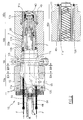
- Figure 2 is a section through the die head 10 of Figure 1 taken on the vertical axial plane.
- Figure 3 is a detail of Figure 2, regarding the upstream portion of the female element of the die head 10.
- Figure 4 is a section on the plane IV-IV of Figure 3.
- Figures 5A and 5B are sections on the planes VA and VB of Figure 2 respectively.
- Figure 6 is a perspective view of the machine 30 of Figure 1 for forming a mixture of fibres.
- Figure 7 is a section through a detail of Figure 6, taken on the axial plane.
- the extrusion machine of the invention comprises an extrusion die head 10 comprising an axially hollow female component 11 and a male component 12 inserted axially into the female component 11, to together define a profiled extrusion channel 20.
- the head 10 comprises, starting from the upstream end, a first portion 10a followed by a second portion 10b and a third portion 10c.
- the male component 12 has an overall frusto-conical lateral surface 12a converging in the downstream direction; in the second portion 10b, the surface 12b of the component 12 is equally frusto-conical; finally, in the third portion 10c, the surface 12c of the component 12 is cylindrical (i.e. formed with generators parallel to the axis of the head 10) and, in the particular case in which a profiled article of circular tubular section (for example a hollow pole) is to be formed, is of circular cross-section.
- the female component 11 has an internal axial through cavity which, in the first portion 10a, has an overall frusto-conical lateral surface 11a converging in the downstream direction, in the second portion 10b it has an equally frusto-conical surface 11b, and finally, in the third portion 10c, it has a cylindrical surface 11c which, in the particular case in which a profiled article of circular tubular section (for example a hollow pole) is to be formed, is of circular cross-section.
- the two components 11 and 12 mate perfectly and hence the respective surfaces 11a and 12a are in mutual contact (with the exception of the concavities 21 described hereinafter); in this portion 10a an insertion fit is thus achieved which supports the male component 12 within the female component 11.
- the surfaces 11b and 11c of the female component 11 have a diameter greater than the corresponding surfaces 12b and 12c of the male component 12, in order to form a tubular channel the cross-section of which is of constant thickness, to define the intermediate portion and downstream portion of the tubular extrusion channel (indicated overall by 20 in the figures).
- an intermediate portion 10i of limited length in which the male component 12 has a cylindrical surface 12i and the female component 11 has an equal surface 11i which lies in contact with the surface 12i; the reason for this is to form a support and centering region for the male component 12 within the female component 11.
- the extrusion channel comprises slight concavities 21 (four in the figures) for removing material on the surfaces 11a and 11i of the female component 11 (see Figures 3, 4, 5A, 5B in particular).
- the longitudinal axis of the concavities 21 commences radially at the inlet 15 and then, after a curve of 90 degrees (Figure 3), extends axially downstream until it opens into the portion 20b of the channel 20, corresponding to the portion 10b.
- these concavities 21 involve the entire circumference of the cross-section, hence the channel 20 extends without interruptions through 360 degrees (see Figure 5A in particular); in contrast on the surface 11i, the concavities 21 have a more limited extension in cross-section, such that between them there are defined four projecting regions 22 having the same diameter as the male component 12, in which the surface 12i of the male component 12 adheres to the surface 11i of the female component 11 (see Figure 5B in particular).
- the purpose of the concavities 21 is to convey the fluid material, entering through the inlet 15, to the portion 20b of the channel 20, the regions 22 acting as a support for the male component 12.
- the die head 10 is connected, via the inlet 15, to a machine for introducing synthetic resin-based fluid material under pressure, in particular to a machine 30 for forming a mixture of reinforcing fibres of limited length and synthetic resin.
- the machine 30 is constructed in accordance with the simultaneous Italian invention patent application in the name of the same applicants.
- the machine 30 comprises a screw conveyor 31, having two screw augers 32 counter-rotating within corresponding channels 33 substantially adhering to the profile of the screws 32, fed upstream by a fibre feed device 35 provided with rotary entrainment/mixing means for the fibres and arranged to introduce the fibres into the initial section 31a of the screw conveyor 31, through an inlet port 34 the axis of which is perpendicular to the plane defined by the two axes of the screw augers 32.
- the fibre feed device 35 comprises a hopper 36 of substantially vertical axis, positioned on the inlet port 34 provided on the upper region of the conveyor 31, for introducing fibrous material into this latter.
- a hopper 36 of substantially vertical axis, positioned on the inlet port 34 provided on the upper region of the conveyor 31, for introducing fibrous material into this latter.
- two motorized shafts 37a provided with elastic blades 37 rotating about an axis parallel to the plane defined by the two axes of the screw augers 32.
- Said blades 37 have a length such as to interfere, at their ends, with the lower portion of the hopper 36 such that, during rotation, the blades 37 flex when they interfere with said lower portion, and then elastically resume their normal profile when the blade rises higher, to lie immersed in the mass of fibrous material contained in the hopper (see Figure 7).
- a following section 31b Downstream of the initial section 31a of the conveyor 31 there is provided a following section 31b into which synthetic resin is injected in the molten state.
- this is introduced into the conveyor 31 at ambient temperature in a substantially liquid state by simple injectors 41 fed by pumps (of known type, not shown in the figures), such as to form within the section 31b a mixture comprising from 50% to 98% of fibres.
- the section 31b comprises a portion in which the screws 32 are shaped to provide mixing, to render the fibre-resin mixture more homogeneous, followed by a final portion in which the screws are shaped to provide an effective axial thrust to introduce the fluid fibre-resin material into the head 10 at sufficiently high pressure.
- the male component 12 comprises in its interior, along the upstream part (portions 10a and 10i) of the extrusion channel 20, a plurality of tubular guides 51 provided with respective internal channels within which thin sheaves of continuous fibres F are made to slide; the guides 51 are positioned in channels 17, parallel to the axis of the channel 20, their downstream ends opening onto the surface 12b within the intermediate portion 20b of the channel 20, where the form of this channel generally converges in the downstream direction.
- the fibres F arrive at the guides 51 by unwinding from large bobbins 52 supported by a frame 53.
- thermosetting resin As is well known, the resin must be maintained at a suitable temperature to prevent excessive hardening on heating.
- a system of channels (known per se) is provided, through which a conditioning fluid is circulated to maintain the temperature of the material within suitable values.
- the male component 12 is provided internally with ducting 43 fed by two channels 44 inserted into the upstream part of the male component 12, for entry and exit of the conditioning fluid respectively.
- the female component 11 is also provided internally with ducting 45, positioned in correspondence with the ducting 43 and acting together with it.
- the action of the rotary blades 37 is particularly effective in eliminating the bridges which the fibres tend to form,so facilitating fibre descent; of particular importance in this respect is the fact that the blades 37 flex against the lower portion of the hopper, and in resuming their proper shape repeatedly strike (as a loaded spring) the fibrous mass accumulated in that region, to move it and mix it, with an effectiveness which, as has been found experimentally, greatly facilitates fibre descent through the port 34.
- Synthetic resin (thermosetting) in the molten state is simultaneously introduced into the section 31b of the conveyor 31 via the injectors 41, and is mixed and rendered homogeneous within the section 31b by the rotation of the screw augers.
- the article enters a unit 60 (of known type and shown only schematically in Figure 1) which heats it to cause it to harden, and also pulls the article in a downstream direction in a manner concordant and synchronized with the advancement of the material and of the fibres F through the head 10.
- a unit 60 of known type and shown only schematically in Figure 1 which heats it to cause it to harden, and also pulls the article in a downstream direction in a manner concordant and synchronized with the advancement of the material and of the fibres F through the head 10.
- articles of indefinite length are obtained by an extrusion process and hence with the advantages typical of extrusion, these articles also being reinforced by longitudinal continuous fibres F involving the entire article and providing it with superior mechanical resistance, in particular against bending.
- the invention can be equally used to form articles of thermoplastic resin.
Landscapes
- Engineering & Computer Science (AREA)
- Mechanical Engineering (AREA)
- Manufacturing & Machinery (AREA)
- Extrusion Moulding Of Plastics Or The Like (AREA)
Applications Claiming Priority (2)
| Application Number | Priority Date | Filing Date | Title |
|---|---|---|---|
| ITRE990112 | 1999-11-10 | ||
| IT1999RE000112A IT1311045B1 (it) | 1999-11-10 | 1999-11-10 | Macchina e metodo di estrusione per realizzare manufatti profilati inresina sintetica rinforzata da fibre continue. |
Publications (2)
| Publication Number | Publication Date |
|---|---|
| EP1099528A2 true EP1099528A2 (fr) | 2001-05-16 |
| EP1099528A3 EP1099528A3 (fr) | 2001-05-23 |
Family
ID=11399508
Family Applications (1)
| Application Number | Title | Priority Date | Filing Date |
|---|---|---|---|
| EP00203872A Withdrawn EP1099528A3 (fr) | 1999-11-10 | 2000-11-06 | Dispositif et procédé pour fabriquer, des profilés en resine synthétique renforcés de fibres continues |
Country Status (2)
| Country | Link |
|---|---|
| EP (1) | EP1099528A3 (fr) |
| IT (1) | IT1311045B1 (fr) |
Family Cites Families (3)
| Publication number | Priority date | Publication date | Assignee | Title |
|---|---|---|---|---|
| US3694131A (en) * | 1971-03-25 | 1972-09-26 | Dart Ind Inc | Die for impregnating and coating filamentary material |
| US4132756A (en) * | 1974-12-20 | 1979-01-02 | Industrie Pirelli, S.P.A. | Process for extruding plastomeric or elastomeric material on filaments |
| DE3619981A1 (de) * | 1986-06-13 | 1987-12-17 | Freudenberg Carl Fa | Verfahren und vorrichtung zur herstellung eines fadenverstaerkten schlauches aus polymerem werkstoff |
-
1999
- 1999-11-10 IT IT1999RE000112A patent/IT1311045B1/it active
-
2000
- 2000-11-06 EP EP00203872A patent/EP1099528A3/fr not_active Withdrawn
Also Published As
| Publication number | Publication date |
|---|---|
| EP1099528A3 (fr) | 2001-05-23 |
| ITRE990112A0 (it) | 1999-11-10 |
| IT1311045B1 (it) | 2002-02-28 |
| ITRE990112A1 (it) | 2001-05-10 |
Similar Documents
| Publication | Publication Date | Title |
|---|---|---|
| EP0995567B1 (fr) | Procédé pour la fabrication de résine thermoplastique modifiée, chargée et renforcée de fibres et une extrudeuse-double-vis pour la mise en oeuvre du procédé | |
| EP1177871B1 (fr) | Procédé et dispositif pour la fabrication des articles en matière plastique renforcée par des fibres longues | |
| EP0771259B1 (fr) | Dispositif de fabrication de pieces en plastique a fibres de renforcement incorporees | |
| EP0979719A2 (fr) | Procédé et extrudeuse de plastification pour produire des compositions polymères renforcées par des fibres | |
| WO1997001424A1 (fr) | Procede et dispositif pour l'impregnation de roving par une matiere plastique | |
| DE2214571B2 (de) | Vorrichtung zum Tränken und Überziehen von fadenförmigem Material mit einem fließfähigen polymeren Harz | |
| EP3730275B1 (fr) | Procédé de compoundage direct des compositions renforcées par des fibres pour la fabrication de pièces moulées en matière plastique et dispositif de compoundage direct | |
| EP1697109B1 (fr) | Procede et dispositif pour appliquer un renfort sur un tube de plastique au moyen d'un procede de soudure a enveloppement | |
| EP3877150A1 (fr) | Tête d'impression pour la fabrication additive de matériaux composites renforcés par des fibres | |
| KR20180067289A (ko) | 전기 통신 광케이블 관 제조장치 및 제조방법 | |
| EP0364828B1 (fr) | Installation d'imprégnation par extrusion | |
| EP0397004B1 (fr) | Procédé et dispositif pour la fabrication de produits d'extrusion résistant au choc et à l'usure en polyéthylène hautement moléculaire | |
| EP1099528A2 (fr) | Dispositif et procédé pour fabriquer, des profilés en resine synthétique renforcés de fibres continues | |
| DE2514307A1 (de) | Schneckengehaeuse fuer einen extruder oder eine spritzgiessmaschine | |
| CN111867805A (zh) | 注塑机以及使用该注塑机的树脂成形体的制造方法 | |
| EP1099525A1 (fr) | Procédé pour la formation d'un mélange à base de résine synthétique et fibres de renforcement | |
| US3341387A (en) | Apparatus and method for filament winding and curing on a plurality of mandrels | |
| DE69215861T2 (de) | Extrusionsdüse | |
| EP1100664B1 (fr) | Dispositif pour la préparation d'une composition chimique réactive en plastique avec interposition de fibres naturelles. | |
| DE3521964C2 (fr) | ||
| DE102015003206B4 (de) | Verfahren und Anlage zum Herstellen eines Fertigteils | |
| KR20090082580A (ko) | 사출장치의 스크류 | |
| DE102017108470B3 (de) | Einschnecken-Plastifiziereinheit und Spritzgießmaschine mit einer Einschnecken-Plastifiziereinheit | |
| DE102016205531A1 (de) | Generatorkopf zur Erzeugung von stabförmigen Strukturelementen, Generator und Verfahren zur Erzeugung von stabförmigen Strukturelementen | |
| EP1293320A1 (fr) | Procédé d'assemblage par injection |
Legal Events
| Date | Code | Title | Description |
|---|---|---|---|
| PUAI | Public reference made under article 153(3) epc to a published international application that has entered the european phase |
Free format text: ORIGINAL CODE: 0009012 |
|
| PUAL | Search report despatched |
Free format text: ORIGINAL CODE: 0009013 |
|
| AK | Designated contracting states |
Kind code of ref document: A2 Designated state(s): AT BE CH CY DE DK ES FI FR GB GR IE LI LU MC NL PT SE TR |
|
| AX | Request for extension of the european patent |
Free format text: AL;LT;LV;MK;RO;SI |
|
| AK | Designated contracting states |
Kind code of ref document: A3 Designated state(s): AT BE CH CY DE DK ES FI FR GB GR IE IT LI LU MC NL PT SE TR |
|
| AX | Request for extension of the european patent |
Free format text: AL;LT;LV;MK;RO;SI |
|
| 17P | Request for examination filed |
Effective date: 20011030 |
|
| AKX | Designation fees paid |
Free format text: AT BE CH CY DE DK ES FI FR GB GR IE LI LU MC NL PT SE TR |
|
| 17Q | First examination report despatched |
Effective date: 20030225 |
|
| STAA | Information on the status of an ep patent application or granted ep patent |
Free format text: STATUS: THE APPLICATION IS DEEMED TO BE WITHDRAWN |
|
| 18D | Application deemed to be withdrawn |
Effective date: 20050722 |