EP1099596A2 - Dispositif de support d'un réceptacle de boissons - Google Patents
Dispositif de support d'un réceptacle de boissons Download PDFInfo
- Publication number
- EP1099596A2 EP1099596A2 EP00119965A EP00119965A EP1099596A2 EP 1099596 A2 EP1099596 A2 EP 1099596A2 EP 00119965 A EP00119965 A EP 00119965A EP 00119965 A EP00119965 A EP 00119965A EP 1099596 A2 EP1099596 A2 EP 1099596A2
- Authority
- EP
- European Patent Office
- Prior art keywords
- holding
- holding device
- carriage
- holding element
- slide
- Prior art date
- Legal status (The legal status is an assumption and is not a legal conclusion. Google has not performed a legal analysis and makes no representation as to the accuracy of the status listed.)
- Granted
Links
Images


Classifications
-
- B—PERFORMING OPERATIONS; TRANSPORTING
- B60—VEHICLES IN GENERAL
- B60N—SEATS SPECIALLY ADAPTED FOR VEHICLES; VEHICLE PASSENGER ACCOMMODATION NOT OTHERWISE PROVIDED FOR
- B60N3/00—Arrangements or adaptations of other passenger fittings, not otherwise provided for
- B60N3/10—Arrangements or adaptations of other passenger fittings, not otherwise provided for of receptacles for food or beverages, e.g. refrigerated
- B60N3/105—Arrangements or adaptations of other passenger fittings, not otherwise provided for of receptacles for food or beverages, e.g. refrigerated for receptables of different size or shape
- B60N3/106—Arrangements or adaptations of other passenger fittings, not otherwise provided for of receptacles for food or beverages, e.g. refrigerated for receptables of different size or shape with adjustable clamping mechanisms
-
- B—PERFORMING OPERATIONS; TRANSPORTING
- B60—VEHICLES IN GENERAL
- B60N—SEATS SPECIALLY ADAPTED FOR VEHICLES; VEHICLE PASSENGER ACCOMMODATION NOT OTHERWISE PROVIDED FOR
- B60N3/00—Arrangements or adaptations of other passenger fittings, not otherwise provided for
- B60N3/10—Arrangements or adaptations of other passenger fittings, not otherwise provided for of receptacles for food or beverages, e.g. refrigerated
- B60N3/102—Arrangements or adaptations of other passenger fittings, not otherwise provided for of receptacles for food or beverages, e.g. refrigerated storable or foldable in a non-use position
Definitions
- the invention relates to a holding device for a beverage container such as a beverage can, a mug or a cup, for inclined installation is provided, for example, in a dashboard of a motor vehicle.
- inclined Installation means that the holding device on an imaginary, inclined plane, is installed at an angle to a horizontal surface.
- the holding device has a slide, which is drawer-like with a sliding guide slidable from an inserted position to an extended position is led. In the extended position, a beverage container is in the holding device adjustable.
- the slide is inclined with the sliding guide in the inclined Level guided.
- On the slide is, for example, a swivel joint Holding element with an adjustment opening attached to adjust the beverage container.
- the holding element can be pivoted upwards from the slide, for example in an approximately horizontal position.
- the invention has for its object a holding device of the above explained type in such a way that it can be carried out flat and that inclined installation a set beverage container at least approximately vertically keeps standing.
- the invention Holding device has a storage element, which is preferably a flat component is formed and that is movable with a guide down on the carriage of the holding device is led.
- Guides include lever or swivel guides into consideration.
- the storage element is moved when moving placed in an approximately horizontal position at a distance below the holding element.
- a beverage container is set in the setting opening of the holding element adjustable on the shelf.
- the beverage container placed on the storage element is at least approximately vertical despite the inclined installation of the holding device held.
- the holding device has a gear, in particular a lever gear, which connects the parking element with the holding element and that the storage element moves downward when the holding element pivots upward.
- the gear is thus driven by the holding element and in turn drives the shut-off element on, the movement of the storage element is derived from the holding element.
- the holding device according to the invention has the advantage that it can be made flat is and therefore little space, for example in a dashboard of a motor vehicle needed.
- Another advantage of the invention is that it has an inclined, for example an inclination of a dashboard adapted installation allows and a set beverage container is still upright and safe against tipping holds.
- the holding device has a locking mechanism that the holding element in its upwardly pivoted position against an (accidental) Depress locks.
- it can be the gearbox that is the storage element connects to the holding element, be designed as a ratchet that the holding element in its upwardly pivoted position against movement by depression locks on the holding element.
- Unlocking can be done, for example, by moving it the slide from the extended position in the direction of the inserted Position.
- the storage element has a drip tray, those possibly while driving the motor vehicle from the one set in the holding device Beverage container catches spilling liquid. It can be the storage element itself be designed as a drip tray or, for example, a drip tray removably inserted into the storage element.
- the holding device has a swivel fitting for the storage element with which the storage element can be moved downwards and is pivotally attached to the slide.
- the downward mobility and the Swiveling can be achieved, for example, by means of a swivel lever gear.
- the pivoting and movability of the storage element can also be downward can be achieved in that the pivot fitting has a pivot axis in a rear Area or via a connection rigid with the storage element behind the Has storage element.
- the holding device has at least one Spring element, which pivots the holding element up and thereby over the Gear moves the storage element down.
- the spring element moves when moving the slide from the inserted to the extended position Holding element up and the storage element down, d. H. the holding device moves automatically into the extended position by moving its slide in a position of use in which a beverage container is adjustable in the holding device is.
- the sliding of the slide in the extended Position can also be spring-operated, so that the placement of the invention Holding device in the use position in which a beverage container is adjustable, limited to a simple unlocking of a locking device.
- the spring element can, for example, directly on the holding element or also indirectly via the storage element or the one connecting the storage element to the holding element Grip the gearbox on the holding element. Multiple spring elements can also be used Find use that attack different parts of the holding device.
- the holding device has a reset device for the holding element, which the holding element when moving the carriage from the extended to the retracted position down on the sled pivots.
- a reset device for the holding element, which the holding element when moving the carriage from the extended to the retracted position down on the sled pivots.
- the pivoting takes place by means of the reset device of the holding element downwards and moving the storage element upwards automatically by moving the carriage, the holding element does not have to be moved of the slide can be pivoted downwards into the inserted position.
- the reset device preferably also unlocks the locking mechanism that holds the holding element locks in the upward swung position against depression, provided there is such a lock.
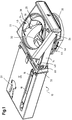
- the holding device 10 according to the invention shown in the drawing is one inclined installation, for example in a dashboard, not shown, of a motor vehicle intended.
- a position of use of the holding device 10 in which a beverage container, not shown, for example a beverage can, a cup or a cup is adjustable in the holding device 10 and by the holding device 10 is held securely against tipping.
- the holding device 10 is for an inclined installation, d. H. for installation in an imaginary, inclined plane provided at an angle to an imaginary, horizontal plane.
- the inclined The installation position of the holding device 10 can be seen in FIG. 2.
- the holding device 10 has a flat housing 12 which is open on a front side, in which a carriage 14 is slidably guided in the manner of a drawer.
- the housing 12 forms a sliding guide for the slide 14.
- the slide 14 is not made of one shown, inserted into the housing 12 in the position shown, from the Housing 12 extended position slidably guided in the housing 12.
- One in the Drawing not visible, arranged on a back of the carriage 14 roller spring (Tension spring), the free, rollable end near the front at the bottom of the housing 12 is attached, moves the carriage 14 in the illustrated, extended Position.
- the displacement movement is damped by a rotation damping element 16, that is inserted into an upper side of the slide 14 and its gearwheel a rack 18 of the housing 12 combs.
- a holding element 22 which is approximately square in plan view is also on the slide 14 a circular setting opening 24 for setting the beverage container, not shown arranged.
- the holding element 22 is with a swivel joint 26 upwards pivotally attached to the carriage 14.
- the swivel joint 26 is a pivot connection formed and close to a front end of the carriage 14 or of the holding element 22 arranged.
- the holding element 22 is around the swivel joint 26 from a position, not shown, lying flat on the carriage 14 in the in the drawing shown, pivoted upward position. In the not shown, lying on the carriage 14, the carriage 14 is together insertable into the housing 12 with the holding element 22. In the swung up Position takes the holding element 22 approximately a horizontal position on.
- a spring-loaded compensating flap in a manner known per se 28 arranged when setting the beverage container, not shown pressed into the setting opening 24 of the holding element 22 downwards and to the side and the set beverage container against the opposite one Side of the setting opening 24 presses.
- the compensating flap 28 adapts the invention Holding device 10 automatically on beverage containers different Diameter.
- a plate-shaped storage element 30 with an upstanding circumferential edge arranged. Due to its upstanding, circumferential The edge is the storage element 30 as a drip tray for from the set beverage container spilling liquid.
- the storage element has on its back 30 a rigid extension 32 (FIG. 2) which is integral with it and which is inclined protrudes backwards and upwards from the storage element 30. Via a pivot connection 34 at the rear end of the extension 32 is the storage element 30 with the carriage 14 of the holding device 10 according to the invention.
- the course of the extension 32 and its pivot pin connection 34 with the slide 14 is shown in FIG. 4 shown with dashed lines.
- the extension 32 with the pivot pin 34 forms one Swivel fitting for the storage element 30, with which the storage element 30 from a not shown, in the slide 14 in the position shown in the drawing Position is pivotable downwards and movable.
- One through the pivot connection 34 defined pivot axis is behind the actual one Abstellelement 30.
- the lever gear has a lever 36, which can be pivoted approximately in its center via a pivot pin connection 38 (FIG. 4) is connected to the carriage 14. At one end, the lever 36 points to both Sides an elongated hole 40 into which a pivot pin 42 of the holding element 22 engages. As a result, the lever 36 is pivotable and displaceable with the holding element 22 connected. At its other end, the lever 36 has one on each side protruding pin 44 on, in an elongated hole 46 in the upstanding, circumferential Edge of the parking element 30 engages. About the pin 44 and the slot 46, the lever 36 is pivotally and slidably connected to the storage element 30.
- the lever 36 movably connects the storage element 30 to the holding element 22. Pivots the holding element 22 up to the position shown, moves and the lever 36 pivots the storage element 30 from the position in the carriage 14 in the illustrated, approximately horizontal position down. In the swung down Position is one set in the setting opening 24 of the holding element 22 Beverage container can be placed on the storage element 30.
- the holding device 10 has a reset device, which during Insert the carriage 14 into the housing 12, the holding element 22 in the on the Carriage 14 swings down position.
- the reset device points a lever 48 on a pivot pin 50 on its rear End is pivotally mounted in the region of a rear end of the carriage 14.
- On the reset lever 48 has laterally protruding pins 52 at its front end, which engage in a kinked elongated hole 54 in the lever 36, which is the storage element 30 connects to the holding element 22.
- the holding device according to the invention 10 has a spring element 56 which indirectly via the reset lever 48 Holding element 22 presses up into the position shown.
- the spring element 56 is formed in the illustrated embodiment as a torsion coil spring 56, the placed on the pin 50, which connects the reset lever 48 to the slide 14 is and whose one leg is supported on a bottom of the carriage 14 and whose other leg attacks the reset lever 48 and pushes it upwards.
- the reset lever 48 pivots via the lever 36, which movably connects the parking element 30 to the holding element 22, the holding element 22 upwards and at the same time moves and pivots the storage element 30 in the position shown down.
- the reset lever 48 has a laterally protruding one Reset pin 58, which passes through a slot 60 of the carriage 14 laterally.
- the reset pin 58 are in a groove 62 which is on the inside of side walls of the Housing 12 of the holding device 10 are attached, guided.
- the groove 62 is shown in Figure 4 with a dashed line to distinguish it from the dashed lines with which the Extension 32 of the shut-off element 30, the reset lever 48 and the spring element 56 are able to differentiate.
- the groove 62 runs in the longitudinal direction of the housing 12, ie in the sliding direction of the slide 14. To open the housing 12 the front side of the groove 62 widens to form an inclined surface 64 diagonally upwards.
- the slide slides Reset pin 58 of the reset lever 48 first on the inclined surface 64 of the groove 62 along.
- the reset pin 48 and together with it the reset lever 48 thereby pressed down against the force of the spring element 56. Panned the reset lever 48 via the connecting element 30 with the holding element 22 Lever 36, the holding element 22 in the resting on the carriage 14 position down and the parking element 30 into the position in the carriage 14 after above, so that the slide 14 together with the holding element 22 and the storage element 30 can be inserted into the housing 12.
- the reset lever 48 and the lever 36, the parking element 30 with the holding element 22 connects, form a locking mechanism that holds the holding element 22 against depression locks in the pivoted up position: the end of the elongated hole 54 in Lever 36, in which the pin 52 of the reset lever 48 when pivoted upward Reset lever 48 and upwardly pivoted holding element 22 as in the drawing engages shown, extends in the tangential direction to the pin 50 with which the reset lever 48 is pivotally connected to the carriage 14.
- Slot 54 is the lever 36 in its position shown in the drawing against Swivel locked by a moment engaging the lever 36.
- the lever 36 thereby in turn locks the holding element 22 in its pivoted upward Position against depressing the holding element 22 by pressure from above on the Holding element 22.
- the holding element 22 can be pivoted downward by pressure on the reset lever 48 down, as he when inserting the carriage 14 in the Housing 12 from the inclined surface 64 via the reset pin 58 of the reset lever 48 is exercised on the reset lever 48.
- the one that swings down Reset lever 48 pivots the connecting element 30 with the holding element 22 Lever 36 and about this the holding element 22 down and at the same time Parking element 30 upwards.
Landscapes
- Engineering & Computer Science (AREA)
- Physics & Mathematics (AREA)
- Thermal Sciences (AREA)
- Transportation (AREA)
- Mechanical Engineering (AREA)
- Passenger Equipment (AREA)
- Vehicle Step Arrangements And Article Storage (AREA)
- Supplying Of Containers To The Packaging Station (AREA)
- Control And Other Processes For Unpacking Of Materials (AREA)
Applications Claiming Priority (2)
| Application Number | Priority Date | Filing Date | Title |
|---|---|---|---|
| DE19954670A DE19954670A1 (de) | 1999-11-13 | 1999-11-13 | Haltevorrichtung für einen Getränkebehälter |
| DE19954670 | 1999-11-13 |
Publications (3)
| Publication Number | Publication Date |
|---|---|
| EP1099596A2 true EP1099596A2 (fr) | 2001-05-16 |
| EP1099596A3 EP1099596A3 (fr) | 2003-08-13 |
| EP1099596B1 EP1099596B1 (fr) | 2006-06-07 |
Family
ID=7928944
Family Applications (1)
| Application Number | Title | Priority Date | Filing Date |
|---|---|---|---|
| EP00119965A Expired - Lifetime EP1099596B1 (fr) | 1999-11-13 | 2000-09-14 | Dispositif de support d'un réceptacle de boissons |
Country Status (5)
| Country | Link |
|---|---|
| EP (1) | EP1099596B1 (fr) |
| JP (1) | JP2001180362A (fr) |
| KR (1) | KR20010050687A (fr) |
| AT (1) | ATE328759T1 (fr) |
| DE (2) | DE19954670A1 (fr) |
Cited By (4)
| Publication number | Priority date | Publication date | Assignee | Title |
|---|---|---|---|---|
| GB2379203A (en) * | 2001-08-29 | 2003-03-05 | Nifco Inc | Container holder |
| WO2004035347A1 (fr) * | 2002-10-11 | 2004-04-29 | Sego Gmbh | Systeme de support de gobelet ou de bouteille destine notamment a un vehicule automobile |
| FR2996811A1 (fr) * | 2012-10-16 | 2014-04-18 | Faurecia Interieur Ind | Dispositif retractable de support de recipient et piece d'equipement de vehicule dotee d'un tel dispositif |
| CN107336652A (zh) * | 2017-07-24 | 2017-11-10 | 延锋安道拓座椅有限公司 | 弹出式杯托 |
Families Citing this family (8)
| Publication number | Priority date | Publication date | Assignee | Title |
|---|---|---|---|---|
| DE10227646B3 (de) * | 2002-06-20 | 2004-03-04 | Daimlerchrysler Ag | Cupholderanordnung für Fahrzeuge |
| DE102004009111A1 (de) * | 2004-02-25 | 2005-09-22 | Daimlerchrysler Ag | Cupholder |
| DE102007013981A1 (de) * | 2007-03-23 | 2008-09-25 | Fischer Automotive Systems Gmbh | Halter für einen Getränkebehälter |
| DE102007054488A1 (de) * | 2007-11-15 | 2009-05-20 | Fischer Automotive Systems Gmbh & Co. Kg | Halter für einen Getränkebehälter |
| DE102007058763A1 (de) * | 2007-12-06 | 2009-06-10 | Daimler Ag | Haltevorrichtung für einen Innenraum eines Kraftfahrzeugs |
| CN103786621B (zh) * | 2014-01-27 | 2016-01-27 | 宁波帅特龙集团有限公司 | 车用杯托 |
| DE102015200087A1 (de) | 2015-01-07 | 2016-07-07 | Volkswagen Aktiengesellschaft | Haltevorrichtung für einen Getränkebehälter |
| DE102018207510A1 (de) * | 2018-05-15 | 2019-11-21 | Bayerische Motoren Werke Aktiengesellschaft | Ablageeinrichtung für ein Fahrzeug |
Family Cites Families (7)
| Publication number | Priority date | Publication date | Assignee | Title |
|---|---|---|---|---|
| DE4318249A1 (de) * | 1993-06-02 | 1994-12-08 | Paulmann & Crone Gmbh & Co Kg | Vorrichtung zur Halterung von Getränkedosen oder dergleichen Behältnissen im Innenraum von Kraftfahrzeugen |
| DE19507614A1 (de) * | 1995-03-04 | 1996-09-05 | Fischer Artur Werke Gmbh | Halterung für einen Getränkebehälter |
| JP3594045B2 (ja) * | 1995-09-11 | 2004-11-24 | 株式会社ニフコ | カップホルダーユニット |
| DE19534840A1 (de) * | 1995-09-20 | 1997-03-27 | Happich Gmbh Gebr | Einbau-Vorrichtung |
| US5845888A (en) * | 1997-07-17 | 1998-12-08 | Prince Corporation | Retractable container holder |
| DE29810872U1 (de) * | 1998-06-17 | 1998-08-13 | Sarnatech Paulmann & Crone GmbH, 58511 Lüdenscheid | Vorrichtung für Kraftfahrzeuge zum Haltern von Getränkebehältern |
| DE29901124U1 (de) * | 1999-01-23 | 1999-05-06 | plastic concept gmbh Systemteile aus Kunststoff, 02742 Neusalza-Spremberg | Verstellbare Behälteraufnahme für Fahrzeuge aller Art |
-
1999
- 1999-11-13 DE DE19954670A patent/DE19954670A1/de not_active Ceased
-
2000
- 2000-09-14 EP EP00119965A patent/EP1099596B1/fr not_active Expired - Lifetime
- 2000-09-14 DE DE50012904T patent/DE50012904D1/de not_active Expired - Fee Related
- 2000-09-14 AT AT00119965T patent/ATE328759T1/de not_active IP Right Cessation
- 2000-09-28 KR KR1020000056918A patent/KR20010050687A/ko not_active Withdrawn
- 2000-11-10 JP JP2000344185A patent/JP2001180362A/ja active Pending
Non-Patent Citations (1)
| Title |
|---|
| None |
Cited By (7)
| Publication number | Priority date | Publication date | Assignee | Title |
|---|---|---|---|---|
| GB2379203A (en) * | 2001-08-29 | 2003-03-05 | Nifco Inc | Container holder |
| US6685152B2 (en) | 2001-08-29 | 2004-02-03 | Nifco Inc. | Container holder |
| GB2379203B (en) * | 2001-08-29 | 2004-12-15 | Nifco Inc | Container holder |
| WO2004035347A1 (fr) * | 2002-10-11 | 2004-04-29 | Sego Gmbh | Systeme de support de gobelet ou de bouteille destine notamment a un vehicule automobile |
| FR2996811A1 (fr) * | 2012-10-16 | 2014-04-18 | Faurecia Interieur Ind | Dispositif retractable de support de recipient et piece d'equipement de vehicule dotee d'un tel dispositif |
| CN107336652A (zh) * | 2017-07-24 | 2017-11-10 | 延锋安道拓座椅有限公司 | 弹出式杯托 |
| CN107336652B (zh) * | 2017-07-24 | 2019-04-12 | 延锋安道拓座椅有限公司 | 弹出式杯托 |
Also Published As
| Publication number | Publication date |
|---|---|
| JP2001180362A (ja) | 2001-07-03 |
| ATE328759T1 (de) | 2006-06-15 |
| KR20010050687A (ko) | 2001-06-15 |
| DE50012904D1 (de) | 2006-07-20 |
| DE19954670A1 (de) | 2001-05-17 |
| EP1099596B1 (fr) | 2006-06-07 |
| EP1099596A3 (fr) | 2003-08-13 |
Similar Documents
| Publication | Publication Date | Title |
|---|---|---|
| EP1059198B1 (fr) | Dispositif de support d'un réceptacle de boissons | |
| EP0730995B1 (fr) | Support pour un conteneur de boisson | |
| EP1176050B1 (fr) | Dispositif de support d'un réceptacle de boissons | |
| DE19528488C1 (de) | Halterung für zwei Getränkebehälter | |
| EP1093962A2 (fr) | Support pour récipients pour boissons | |
| EP1099596B1 (fr) | Dispositif de support d'un réceptacle de boissons | |
| DE19616774C2 (de) | Trinkgefäßhalter für Fahrzeuge | |
| DE202007013356U1 (de) | Vorrichtung zur Verstellung eines Bodens oder Abstellers eines Kühl- und/oder Gefriergerätes | |
| EP3941310B1 (fr) | Mécanisme de coulissement et de pivotement d'une tablette d'un meuble ou d'un appareil électroménager, et meuble ou appareil électroménager | |
| DE102006020264B4 (de) | Aufnahmefach für den Innenraum eines Fahrzeugs | |
| DE19821313C2 (de) | Halterung für einen Getränkebehälter in einem Kraftwagen | |
| DE10109119A1 (de) | Getränkehalter | |
| EP0730994B1 (fr) | Support pour un conteneur de boisson | |
| DE20204882U1 (de) | Halter für einen Getränkebehälter | |
| DE19636825C2 (de) | Haltevorrichtung für einen Getränkebehälter | |
| DE202007011662U1 (de) | Vorrichtung zur Halterung von Behältern, insbesondere Getränkedosen, Bechern o.dgl. Trinkgefäßen | |
| EP1281567A2 (fr) | Support pour contenants à boisson | |
| DE10317523A1 (de) | Haltevorrichtung für einen Getränkebehälter | |
| EP1238854B1 (fr) | Dispositif de maintien de récipients à boisson dans des véhicules automobiles | |
| DE19603590C1 (de) | Trinkgefäßhalter für Fahrzeuge | |
| DE19956649A1 (de) | Halter für einen Getränkebehälter in einem Kraftwagen | |
| DE19630528A1 (de) | Vorrichtung zum Halten zweier Getränkebehälter in der Mittelkonsole eines Kraftwagens | |
| DE19846028C2 (de) | Halter für Getränkebehälter | |
| EP1972492B1 (fr) | Support de réservoir de boissons | |
| DE4445862C1 (de) | Vorrichtung zur Halterung von Getränkedosen |
Legal Events
| Date | Code | Title | Description |
|---|---|---|---|
| PUAI | Public reference made under article 153(3) epc to a published international application that has entered the european phase |
Free format text: ORIGINAL CODE: 0009012 |
|
| AK | Designated contracting states |
Kind code of ref document: A2 Designated state(s): AT BE CH CY DE DK ES FI FR GB GR IE IT LI LU MC NL PT SE |
|
| AX | Request for extension of the european patent |
Free format text: AL;LT;LV;MK;RO;SI |
|
| PUAL | Search report despatched |
Free format text: ORIGINAL CODE: 0009013 |
|
| AK | Designated contracting states |
Designated state(s): AT BE CH CY DE DK ES FI FR GB GR IE IT LI LU MC NL PT SE |
|
| AX | Request for extension of the european patent |
Extension state: AL LT LV MK RO SI |
|
| 17P | Request for examination filed |
Effective date: 20040114 |
|
| AKX | Designation fees paid |
Designated state(s): AT BE CH CY DE DK ES FI FR GB GR IE IT LI LU MC NL PT SE |
|
| 17Q | First examination report despatched |
Effective date: 20050504 |
|
| GRAP | Despatch of communication of intention to grant a patent |
Free format text: ORIGINAL CODE: EPIDOSNIGR1 |
|
| GRAS | Grant fee paid |
Free format text: ORIGINAL CODE: EPIDOSNIGR3 |
|
| GRAA | (expected) grant |
Free format text: ORIGINAL CODE: 0009210 |
|
| PGFP | Annual fee paid to national office [announced via postgrant information from national office to epo] |
Ref country code: DE Payment date: 20060523 Year of fee payment: 7 |
|
| AK | Designated contracting states |
Kind code of ref document: B1 Designated state(s): AT BE CH CY DE DK ES FI FR GB GR IE IT LI LU MC NL PT SE |
|
| PG25 | Lapsed in a contracting state [announced via postgrant information from national office to epo] |
Ref country code: IT Free format text: LAPSE BECAUSE OF FAILURE TO SUBMIT A TRANSLATION OF THE DESCRIPTION OR TO PAY THE FEE WITHIN THE PRESCRIBED TIME-LIMIT;WARNING: LAPSES OF ITALIAN PATENTS WITH EFFECTIVE DATE BEFORE 2007 MAY HAVE OCCURRED AT ANY TIME BEFORE 2007. THE CORRECT EFFECTIVE DATE MAY BE DIFFERENT FROM THE ONE RECORDED. Effective date: 20060607 Ref country code: GB Free format text: LAPSE BECAUSE OF FAILURE TO SUBMIT A TRANSLATION OF THE DESCRIPTION OR TO PAY THE FEE WITHIN THE PRESCRIBED TIME-LIMIT Effective date: 20060607 Ref country code: NL Free format text: LAPSE BECAUSE OF FAILURE TO SUBMIT A TRANSLATION OF THE DESCRIPTION OR TO PAY THE FEE WITHIN THE PRESCRIBED TIME-LIMIT Effective date: 20060607 Ref country code: IE Free format text: LAPSE BECAUSE OF FAILURE TO SUBMIT A TRANSLATION OF THE DESCRIPTION OR TO PAY THE FEE WITHIN THE PRESCRIBED TIME-LIMIT Effective date: 20060607 Ref country code: FI Free format text: LAPSE BECAUSE OF FAILURE TO SUBMIT A TRANSLATION OF THE DESCRIPTION OR TO PAY THE FEE WITHIN THE PRESCRIBED TIME-LIMIT Effective date: 20060607 |
|
| REG | Reference to a national code |
Ref country code: GB Ref legal event code: FG4D Free format text: NOT ENGLISH |
|
| REG | Reference to a national code |
Ref country code: CH Ref legal event code: EP |
|
| REG | Reference to a national code |
Ref country code: IE Ref legal event code: FG4D Free format text: LANGUAGE OF EP DOCUMENT: GERMAN |
|
| REF | Corresponds to: |
Ref document number: 50012904 Country of ref document: DE Date of ref document: 20060720 Kind code of ref document: P |
|
| PG25 | Lapsed in a contracting state [announced via postgrant information from national office to epo] |
Ref country code: DK Free format text: LAPSE BECAUSE OF FAILURE TO SUBMIT A TRANSLATION OF THE DESCRIPTION OR TO PAY THE FEE WITHIN THE PRESCRIBED TIME-LIMIT Effective date: 20060907 Ref country code: SE Free format text: LAPSE BECAUSE OF FAILURE TO SUBMIT A TRANSLATION OF THE DESCRIPTION OR TO PAY THE FEE WITHIN THE PRESCRIBED TIME-LIMIT Effective date: 20060907 |
|
| PG25 | Lapsed in a contracting state [announced via postgrant information from national office to epo] |
Ref country code: ES Free format text: LAPSE BECAUSE OF FAILURE TO SUBMIT A TRANSLATION OF THE DESCRIPTION OR TO PAY THE FEE WITHIN THE PRESCRIBED TIME-LIMIT Effective date: 20060918 |
|
| PG25 | Lapsed in a contracting state [announced via postgrant information from national office to epo] |
Ref country code: LI Free format text: LAPSE BECAUSE OF NON-PAYMENT OF DUE FEES Effective date: 20060930 Ref country code: CH Free format text: LAPSE BECAUSE OF NON-PAYMENT OF DUE FEES Effective date: 20060930 Ref country code: BE Free format text: LAPSE BECAUSE OF NON-PAYMENT OF DUE FEES Effective date: 20060930 Ref country code: MC Free format text: LAPSE BECAUSE OF NON-PAYMENT OF DUE FEES Effective date: 20060930 |
|
| PG25 | Lapsed in a contracting state [announced via postgrant information from national office to epo] |
Ref country code: PT Free format text: LAPSE BECAUSE OF FAILURE TO SUBMIT A TRANSLATION OF THE DESCRIPTION OR TO PAY THE FEE WITHIN THE PRESCRIBED TIME-LIMIT Effective date: 20061107 |
|
| NLV1 | Nl: lapsed or annulled due to failure to fulfill the requirements of art. 29p and 29m of the patents act | ||
| GBV | Gb: ep patent (uk) treated as always having been void in accordance with gb section 77(7)/1977 [no translation filed] |
Effective date: 20060607 |
|
| REG | Reference to a national code |
Ref country code: IE Ref legal event code: FD4D |
|
| PLBE | No opposition filed within time limit |
Free format text: ORIGINAL CODE: 0009261 |
|
| STAA | Information on the status of an ep patent application or granted ep patent |
Free format text: STATUS: NO OPPOSITION FILED WITHIN TIME LIMIT |
|
| EN | Fr: translation not filed | ||
| REG | Reference to a national code |
Ref country code: CH Ref legal event code: PL |
|
| 26N | No opposition filed |
Effective date: 20070308 |
|
| PG25 | Lapsed in a contracting state [announced via postgrant information from national office to epo] |
Ref country code: AT Free format text: LAPSE BECAUSE OF NON-PAYMENT OF DUE FEES Effective date: 20060914 |
|
| BERE | Be: lapsed |
Owner name: FISCHERWERKE ARTUR FISCHER G.M.B.H. & CO. KG Effective date: 20060930 |
|
| PG25 | Lapsed in a contracting state [announced via postgrant information from national office to epo] |
Ref country code: FR Free format text: LAPSE BECAUSE OF FAILURE TO SUBMIT A TRANSLATION OF THE DESCRIPTION OR TO PAY THE FEE WITHIN THE PRESCRIBED TIME-LIMIT Effective date: 20070309 Ref country code: GR Free format text: LAPSE BECAUSE OF FAILURE TO SUBMIT A TRANSLATION OF THE DESCRIPTION OR TO PAY THE FEE WITHIN THE PRESCRIBED TIME-LIMIT Effective date: 20060908 |
|
| PG25 | Lapsed in a contracting state [announced via postgrant information from national office to epo] |
Ref country code: LU Free format text: LAPSE BECAUSE OF NON-PAYMENT OF DUE FEES Effective date: 20060914 Ref country code: DE Free format text: LAPSE BECAUSE OF NON-PAYMENT OF DUE FEES Effective date: 20080401 |
|
| PG25 | Lapsed in a contracting state [announced via postgrant information from national office to epo] |
Ref country code: CY Free format text: LAPSE BECAUSE OF FAILURE TO SUBMIT A TRANSLATION OF THE DESCRIPTION OR TO PAY THE FEE WITHIN THE PRESCRIBED TIME-LIMIT Effective date: 20060607 Ref country code: FR Free format text: LAPSE BECAUSE OF FAILURE TO SUBMIT A TRANSLATION OF THE DESCRIPTION OR TO PAY THE FEE WITHIN THE PRESCRIBED TIME-LIMIT Effective date: 20060607 |