EP1099604B1 - Hupbetätigungseinrichtung für Kraftfahrzeuglenkrad - Google Patents
Hupbetätigungseinrichtung für Kraftfahrzeuglenkrad Download PDFInfo
- Publication number
- EP1099604B1 EP1099604B1 EP00830633A EP00830633A EP1099604B1 EP 1099604 B1 EP1099604 B1 EP 1099604B1 EP 00830633 A EP00830633 A EP 00830633A EP 00830633 A EP00830633 A EP 00830633A EP 1099604 B1 EP1099604 B1 EP 1099604B1
- Authority
- EP
- European Patent Office
- Prior art keywords
- steering
- wheel
- actuating element
- stud
- spring
- Prior art date
- Legal status (The legal status is an assumption and is not a legal conclusion. Google has not performed a legal analysis and makes no representation as to the accuracy of the status listed.)
- Expired - Lifetime
Links
Images


Classifications
-
- B—PERFORMING OPERATIONS; TRANSPORTING
- B60—VEHICLES IN GENERAL
- B60R—VEHICLES, VEHICLE FITTINGS, OR VEHICLE PARTS, NOT OTHERWISE PROVIDED FOR
- B60R21/00—Arrangements or fittings on vehicles for protecting or preventing injuries to occupants or pedestrians in case of accidents or other traffic risks
- B60R21/02—Occupant safety arrangements or fittings, e.g. crash pads
- B60R21/16—Inflatable occupant restraints or confinements designed to inflate upon impact or impending impact, e.g. air bags
- B60R21/20—Arrangements for storing inflatable members in their non-use or deflated condition; Arrangement or mounting of air bag modules or components
- B60R21/203—Arrangements for storing inflatable members in their non-use or deflated condition; Arrangement or mounting of air bag modules or components in steering wheels or steering columns
- B60R21/2035—Arrangements for storing inflatable members in their non-use or deflated condition; Arrangement or mounting of air bag modules or components in steering wheels or steering columns using modules containing inflator, bag and cover attachable to the steering wheel as a complete sub-unit
- B60R21/2037—Arrangements for storing inflatable members in their non-use or deflated condition; Arrangement or mounting of air bag modules or components in steering wheels or steering columns using modules containing inflator, bag and cover attachable to the steering wheel as a complete sub-unit the module or a major component thereof being yieldably mounted, e.g. for actuating the horn switch or for protecting the driver in a non-deployment situation
-
- B—PERFORMING OPERATIONS; TRANSPORTING
- B60—VEHICLES IN GENERAL
- B60Q—ARRANGEMENT OF SIGNALLING OR LIGHTING DEVICES, THE MOUNTING OR SUPPORTING THEREOF OR CIRCUITS THEREFOR, FOR VEHICLES IN GENERAL
- B60Q5/00—Arrangement or adaptation of acoustic signal devices
- B60Q5/001—Switches therefor
- B60Q5/003—Switches therefor mounted on the steering wheel
-
- Y—GENERAL TAGGING OF NEW TECHNOLOGICAL DEVELOPMENTS; GENERAL TAGGING OF CROSS-SECTIONAL TECHNOLOGIES SPANNING OVER SEVERAL SECTIONS OF THE IPC; TECHNICAL SUBJECTS COVERED BY FORMER USPC CROSS-REFERENCE ART COLLECTIONS [XRACs] AND DIGESTS
- Y10—TECHNICAL SUBJECTS COVERED BY FORMER USPC
- Y10T—TECHNICAL SUBJECTS COVERED BY FORMER US CLASSIFICATION
- Y10T74/00—Machine element or mechanism
- Y10T74/20—Control lever and linkage systems
- Y10T74/20576—Elements
- Y10T74/20732—Handles
- Y10T74/20834—Hand wheels
Definitions
- the present invention relates to horn actuating devices for motor-vehicle steering-wheels, particularly steering-wheels provided with an air-bag.
- the actuating element of the device can be constituted by the lower rigid wall of a housing for an air-bag associated with the steering-wheel, or it can be constituted simply by a steering-wheel hub covering element which hides the hub of the steering-wheel from view.
- the object of the present invention is that of further simplifying the structure of the previously proposed steering-wheel so that the horn actuating device can be mounted on this steering-wheel with particularly easy and rapid operations.
- the invention provides a steering-wheel having all the above indicated features wherein said stop means provided at the lower end of each stud projecting from the actuating element are elastically deformable, so as to enable rapid installation of said studs of the actuating element within said guide bushes forming part of said pre-assembled unit.
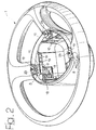
- numeral 1 generally designates the motor-vehicle steering-wheel forming the subject of the previous Italian patent application of the same applicant which has been identified above.
- the steering-wheel 1 comprises a metal frame 2 including a plurality of spokes 3 connecting a rim 4 to a hub (not shown in the drawings) which is to be connected to the steering shaft of the motor-vehicle.
- Each spoke 3 is embedded within a body 5 of plastic material and has an intermediate portion 6 providing a support for the horn actuating device associated with the steering-wheel 1.
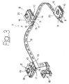
- This device is generally designated by reference numeral 7 and comprises three metal springs 8 each formed by a metal strip bent substantially in a U-shape and arranged horizontally, with its cavity facing towards the steering-wheel axis.
- Each spring 8 has a base portion 9 which rests above a flattened support 10 of plastic material. More precisely, the base portion 9 of each spring 8 rests on, and is in electric contact with, projections 11 of a conductive metal leaf 12 which is embedded within the body of plastic material of support 10.
- the conductive leaf 12 extends into two flattened appendages 13 (figure 3) which project outwardly from the plastic body of support 10 and are in electric contact with an electrically conductive strip 14 which is embedded within the body of a flexible strip 15 of plastic material connecting the three supports 10 to each other.
- a second electrically conductive strip 16 electrically connected to a terminal 17 projecting outwardly from strip 15 at the location of each spring 8 and having its free end fitted at 17a to the respective support 10.
- the flexible strip 15 of plastic material is also rigidly connected to, and preferably is moulded in one piece with the body of plastic material of a connector 18, which is for co-operation with a mating connector for connecting the two electric strips 14, 16 to the electric circuit of the motor-vehicle.
- the connector 18 is a female connector which is for co-operation with a male connector.
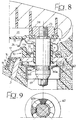
- Each spring 8 has a flexible portion 19 which is pressed elastically against the lower surface of a wall 20 forming the bottom wall of a housing of an air-bag associated with the steering-wheel 1.
- This housing, as well as the air-bag, are not illustrated in the annexed drawings, since these components can be made in any known way and do not fall within the scope of the invention.
- the air-bag housing could also be replaced, as already indicated in the foregoing, simply by a steering-wheel hub covering element.
- the entire air-bag housing is resiliently supported above the spring portions 19 of the three springs 8.
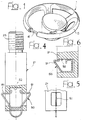
- each stud 21 has a threaded portion 23 which is secured to the respective bottom wall 20 by means of a nut 24 and a lower head 21a adapted to act as a stop element co-operating with the lower end of the respective bush 22 in order to limit the upward travel of the air-bag housing. It is this portion of the device which is modified by the present invention, as will be described hereinafter.
- Each bush 22 also incorporates a stop tooth 25 acting as a stop element for limiting the upward movement of the spring portion 19 of each spring 8.
- the appendage 17 associated with each support 10 constitutes a first fixed electric contact adapted to co-operate with a second movable electric contact constituted by a downwardly bent end 26 of the spring portion 19 of each spring 8.
- the entire unit shown in figure 3, comprising the flexible strip 15 with the connector 18 and the three supports 10 carrying the springs 8, can be assembled and mounted with simple and rapid operations on the frame of the steering-wheel (see figure 2). Due to the flexibility of strip 15, the device has a certain degree of adaptability to different types of steering-wheels.
- each stud 21 was provided with a head 21a adapted to act as a stop means co-operating with the lower end of the respective bush 22. Therefore, in order to mount the air-bag housing, the studs had to be inserted manually from below within bushes 22 and screwed within nuts 24 which were preliminarly secured to element 20.
- each stud 21 has elastically deformable stop means 50 in place of the head 21a, allowing rapid installation from above of the stud 21 within the respective guide bush 22, after that the stud 21 has been preliminarly secured to element 20 by nut 24.
- the stop means 50 are a wire spring forming a pair of radial protrusions 51 which are elastically deformable inwards.
- Each protrusion 51 is sloped in a way to assist its moving back into a cavity 52 of the stud 21 when it engages with the surface of the respective bush 22, during installation.
- Figure 6 shows a variant with a single protrusion 51.
- Figure 7 shows a second embodiment where the stop means are in form of a capsule element 50 fitted on the lower end of the respective stud 21 and having a plurality of radial flaps 53 which are elastically deflectable.
- Figure 8 shows a variant wherein the stud 21 is held in place by a spring element forced within the foam of the steering-wheel, this element being in form a washer 60 with internal radial flaps 60a which are deformed on installation of the stud 21 as a result of the engagement of a conical portion 61 thereof, until they enter a groove 62.
- Figure 9 shows the washer 60 in plan view.
- Figure 10 shows a variant with a split spring ring 60 received within a groove 62 and held by hooks of the steering-wheel frame.
- the lower end of the stud has a head which can be engaged by a wrench, for removal.
Landscapes
- Engineering & Computer Science (AREA)
- Mechanical Engineering (AREA)
- Physics & Mathematics (AREA)
- Acoustics & Sound (AREA)
- Steering Controls (AREA)
- Air Bags (AREA)
- Emergency Alarm Devices (AREA)
Claims (6)
- Kraftfahrzeug-Lenkrad, umfassend:wobei die Federmittel durch eine Vielzahl von Federn (8) gebildet werden, die jeweils einen Basisteil (9), der am Lenkradgestell (2) fest abgestützt ist, und einen flexiblen Teil (19), der mit dem Betätigungselement (20) betreibbar verbunden ist, sowie ein freies Ende (26) aufweisen, das zum Lenkradgestell (2) hin gebogen und ausgelegt ist, um den zweiten elektrischen Kontakt zu formen, der mit dem ersten elektrischen Kontakt (17) zusammenwirkt;ein Metallgestell (2), das eine Nabe, einen Kranz (4) und eine Vielzahl von Speichen (3) umfasst, die die Nabe mit dem Kranz (4) verbinden;ein Betätigungselement (20), das oberhalb des Gestells (2) des Lenkrades so angebracht ist, dass es sich zwischen einer erhabenen Ruhestellung und einer abgesenkten Stellung, die zur Hornbetätigung dient, bewegen lässt;Federmittel (8), die zwischen dem Betätigungselement (20) und dem Lenkradgestell (2) zwischengeschaltet sind, um das Betätigungselement in Richtung seiner erhabenen Stellung vorzuspannen;eine Hornbetätigungseinrichtung, die zwischen dem Betätigungselement und der Nabe zwischengeschaltet ist und mindestens einen ersten elektrischen Kontakt (17), der mit dem Gestell (2) des Lenkrades biegesteif verbunden ist und mindestens einen zweiten elektrischen Kontakt (26) umfasst, der sich mit dem Betätigungselement bewegen lässt und fiir das Zusammenwirken mit dem ersten elektrischen Kontakt (17) zur Bestätigung des Horns ausgelegt ist;
wobei die Federn (8) an den jeweiligen Abstützungen (10) aus Kunststoff angebracht sind, die durch ein flexibles Band (15) aus Kunststoff miteinander verbunden sind, in das zwei leitende Bänder (14, 16) eingebettet wurden, die mit jeder Feder (8) elektrisch verbunden sind und wobei der erste elektrische Kontakt (17) mit denselben Komponenten so zusammenwirkt, dass eine vormontierte Einheit gebildet wird, die am Lenkradgestell (2) untergebracht wird;
und wobei die Kunststoff-Abstützungen (10) der Federn (8) Führungsbuchsen (22) umfassen, wobei die Führungsstehbolzen (21), die biegesteif mit dem Betätigungselement verbunden sind, so verschiebbar sind, dass sie sich mit Hilfe desselben bewegen lassen und wobei Anschlagmittel zwischen dem unteren Ende eines jeden Stehbolzens (21) und dem Lenkradgestell zwischengeschaltet sind, um den Aufwärtshub des Betätigungselements (20) bezogen auf das Lenkradgestell (2) zu begrenzen;
dadurch gekennzeichnet, dass die Anschlagmittel, die am unteren Ende eines jeden Führungsstehbolzens (21) bereitgestellt werden und vom Betätigungselement (20) aus hervorstehen, so elastisch verformbar sind, dass ein schneller Einbau der Stehbolzen (21) des Betätigungselementes (20) in den Führungsbuchsen (22), die Teil der vormontierten Einheit sind, möglich ist. - Lenkrad nach Anspruch 1, dadurch gekennzeichnet, dass die Anschlagmittel durch ein Kapselelement (50) gebildet werden, das am unteren Ende eines jeden Stehbolzens (21) angebracht und mit einer Vielzahl von radial hervorstehenden Klappen (53) versehen ist, die sich elastisch durchbiegen lassen.
- Lenkrad nach einem der vorhergehenden Ansprüche, dadurch gekennzeichnet, dass die Anschlagmittel durch eine Drahtfeder (50) gebildet werden, die eine oder mehrere radiale Ausbuchtungen (51) definiert, die sich elastisch nach innen verformen lassen.
- Lenkrad nach Anspruch 2, dadurch gekennzeichnet, dass die Anschlagmittel durch ein Anschlagfederelement (60) gebildet werden, das in den Schaumstoff des Lenkrades gedrückt wird und mit dem jeweiligen Stehbolzen zusammenwirkt.
- Lenkrad nach Anspruch 4, dadurch gekennzeichnet, dass das Federelement durch eine Scheibe (60) gebildet wird, die eine Vielzahl von inneren radialen Klappen (60a) aufweist, die sich elastisch verformen lassen und ausgelegt sind, um beim Einbau mit einem konischen Teil (61) des jeweiligen Stehbolzens (21) zusammenzuwirken sowie nach dem Einbau in einem Abschnitt (62) mit reduzierten Durchmesser des Stehbolzens aufgenommen zu werden.
- Lenkrad nach Anspruch 1, dadurch gekennzeichnet, dass das Federelement (60) ein geschlitzter Ring ist, der ausgelegt wurde, um beim Einbau mit einem konischen Teil (61) des jeweiligen Stehbolzens (21) zusammenzuwirken sowie nach dem Einbau an einem Abschnitt mit reduziertem Durchmesser (62) des Stehbolzens aufgenommen zu werden.
Priority Applications (1)
| Application Number | Priority Date | Filing Date | Title |
|---|---|---|---|
| EP05028291A EP1657117A3 (de) | 1999-09-24 | 2000-09-22 | Hupbetätigungseinrichtung für Kraftfahrzeuglenkrad |
Applications Claiming Priority (2)
| Application Number | Priority Date | Filing Date | Title |
|---|---|---|---|
| IT1999TO000821A IT1308842B1 (it) | 1999-09-24 | 1999-09-24 | Dispositivo di azionamento di avvisatore acustico per un volante diazionamento. |
| ITTO990821 | 1999-09-24 |
Related Child Applications (1)
| Application Number | Title | Priority Date | Filing Date |
|---|---|---|---|
| EP05028291A Division EP1657117A3 (de) | 1999-09-24 | 2000-09-22 | Hupbetätigungseinrichtung für Kraftfahrzeuglenkrad |
Publications (3)
| Publication Number | Publication Date |
|---|---|
| EP1099604A2 EP1099604A2 (de) | 2001-05-16 |
| EP1099604A3 EP1099604A3 (de) | 2004-09-01 |
| EP1099604B1 true EP1099604B1 (de) | 2005-12-28 |
Family
ID=11418092
Family Applications (2)
| Application Number | Title | Priority Date | Filing Date |
|---|---|---|---|
| EP05028291A Withdrawn EP1657117A3 (de) | 1999-09-24 | 2000-09-22 | Hupbetätigungseinrichtung für Kraftfahrzeuglenkrad |
| EP00830633A Expired - Lifetime EP1099604B1 (de) | 1999-09-24 | 2000-09-22 | Hupbetätigungseinrichtung für Kraftfahrzeuglenkrad |
Family Applications Before (1)
| Application Number | Title | Priority Date | Filing Date |
|---|---|---|---|
| EP05028291A Withdrawn EP1657117A3 (de) | 1999-09-24 | 2000-09-22 | Hupbetätigungseinrichtung für Kraftfahrzeuglenkrad |
Country Status (4)
| Country | Link |
|---|---|
| US (1) | US6457379B1 (de) |
| EP (2) | EP1657117A3 (de) |
| DE (1) | DE60025140T2 (de) |
| IT (1) | IT1308842B1 (de) |
Families Citing this family (48)
| Publication number | Priority date | Publication date | Assignee | Title |
|---|---|---|---|---|
| DE29805207U1 (de) * | 1998-03-23 | 1998-06-04 | TRW Automotive Safety Systems GmbH, 63743 Aschaffenburg | Lenkrad mit Airbag |
| DE20108596U1 (de) * | 2001-05-22 | 2001-09-27 | TRW Automotive Safety Systems GmbH & Co. KG, 63743 Aschaffenburg | Gassackmodul und Fahrzeuglenkrad mit Gassackmodul |
| ITTO20010784A1 (it) * | 2001-08-03 | 2003-02-03 | Breed Automotive Tech | Dispositivo di azionamento di avvisatore acustico per un volante di autoveicolo. |
| US6830263B2 (en) * | 2002-02-08 | 2004-12-14 | Key Safety Systems, Inc. | Method for attaching an airbag module |
| DE20204461U1 (de) * | 2002-03-20 | 2002-07-25 | TRW Automotive Safety Systems GmbH & Co. KG, 63743 Aschaffenburg | Baugruppe mit Rastelementen |
| US6616181B1 (en) * | 2002-04-05 | 2003-09-09 | Breed Automotive Tedhnology, Inc. | Horn mechanism featuring immunity to cushion fold |
| US7437980B2 (en) * | 2002-05-29 | 2008-10-21 | Massachusetts Institute Of Technology | Flux-biased electromagnetic fast tool servo systems and methods |
| US7574947B2 (en) * | 2002-05-29 | 2009-08-18 | Massachusetts Institute Of Technology | Rotary fast tool servo system and methods |
| US7765905B2 (en) * | 2002-05-29 | 2010-08-03 | Massachusetts Institute Of Technology | Magnetic micropositioner and method of providing the same |
| US7275468B2 (en) * | 2002-05-29 | 2007-10-02 | Massachusetts Institute Of Technology | Rotary fast tool servo system and methods |
| DE20219729U1 (de) * | 2002-12-18 | 2003-03-06 | TAKATA-PETRI AG, 63743 Aschaffenburg | Vorrichtung zur Betätigung von elektrischen Funktionsgruppen, insbesondere von Hupen an Lenkrädern von Kraftfahrzeugen |
| GB2398277A (en) * | 2003-02-13 | 2004-08-18 | Autoliv Dev | Spring mounted air bag cover with electrical switch |
| US6942247B2 (en) * | 2003-03-12 | 2005-09-13 | Delphi Technologies, Inc. | Driver airbag formed contact spring |
| US7059631B2 (en) * | 2003-04-29 | 2006-06-13 | Toyoda Gosei Co., Ltd. | Method and apparatus for coupling a driver's side airbag to a steering wheel |
| DE20307096U1 (de) * | 2003-05-07 | 2003-10-09 | Trw Automotive Safety Sys Gmbh | Baugruppe aus einem Lenkrad und einem Gassackmodul |
| DE10324234A1 (de) * | 2003-05-28 | 2004-12-16 | Methode Electronics Malta Ltd. | Bedienschalter für einen Warnsignalgeber in einem Fahrzeug |
| US7268309B2 (en) * | 2003-06-30 | 2007-09-11 | Takata Corporation | Horn switch gear and airbag system |
| JP2005038811A (ja) | 2003-06-30 | 2005-02-10 | Takata Corp | ホーンスイッチ装置及びエアバッグ装置 |
| US7616084B2 (en) * | 2003-10-31 | 2009-11-10 | Massachusetts Institute Of Technology | Variable reluctance fast positioning system and methods |
| US7556281B2 (en) * | 2004-03-16 | 2009-07-07 | Toyoda Gosei Co., Ltd. | Stamped airbag retention members and method of airbag assembly |
| JP2006092921A (ja) * | 2004-09-24 | 2006-04-06 | Takata Corp | ホーンスイッチ装置、エアバッグ装置、ステアリング装置 |
| US7464959B2 (en) * | 2005-03-01 | 2008-12-16 | Trw Vehicle Safety Systems Inc. | Apparatus having a mechanism for limiting the movement of an air bag module relative to a steering wheel |
| US7348508B2 (en) * | 2006-05-05 | 2008-03-25 | Delphi Technologies, Inc. | Horn switch apparatus for a vehicle steering wheel |
| DE102008023004B4 (de) * | 2008-05-09 | 2014-04-03 | Autoliv Development Ab | Hupenaktivierungseinrichtung sowie Sicherheitseinrichtung mit einer solchen Hupenaktivierungseinrichtung |
| US8398115B2 (en) * | 2008-06-25 | 2013-03-19 | Autoliv Development Ab | Vehicle steering wheel |
| US20100219621A1 (en) * | 2009-02-27 | 2010-09-02 | Toyoda Gosei Co., Ltd. | Airbag-equipped steering wheel device |
| DE102009043372B4 (de) * | 2009-09-29 | 2014-03-13 | Autoliv Development Ab | Hupenaktivierungseinrichtung und Sicherheitsanordnung mit einer Hupenaktivierungseinrichtung |
| WO2011100960A2 (de) * | 2010-02-18 | 2011-08-25 | Trw Automotive Safety Systems Gmbh | Lenkrad mit gassackmodul |
| DE102011120490A1 (de) * | 2011-12-08 | 2013-06-13 | Gm Global Technology Operations, Llc | Anordnung eines Lenkrades und eines mit diesem verbundenen Airbag-Moduls bei einem Kraftfahrzeug |
| DE102013114791A1 (de) * | 2013-12-23 | 2015-06-25 | Autoliv Development Ab | Airbagmodul |
| DE202014002484U1 (de) * | 2014-03-21 | 2015-06-29 | Dalphi Metal Espana, S.A. | Hupeneinrichtung für ein Lenkrad und Lenkrad mit einer Hupeneinrichtung |
| JP6596926B2 (ja) * | 2015-05-26 | 2019-10-30 | Joyson Safety Systems Japan株式会社 | コンタクトプレート、コンタクトプレートの取付方法、及びエアバッグ装置 |
| JP6624732B2 (ja) * | 2016-03-29 | 2019-12-25 | 日本プラスト株式会社 | ハンドル |
| DE102016005020B4 (de) * | 2016-04-26 | 2019-08-14 | Dalphi Metal Espana, S.A. | Gassackeinheit und Fahrzeuginsassensicherheitssystem mit einer solchen Gassackeinheit sowie Herstellungsverfahren |
| JP6619293B2 (ja) * | 2016-05-23 | 2019-12-11 | 株式会社ダイセル | ガス発生器 |
| DE102016117001B4 (de) | 2016-09-09 | 2023-05-17 | Autoliv Development Ab | Hupenaktivierungseinrichtung |
| DE102016124530A1 (de) * | 2016-12-15 | 2018-06-21 | Trw Automotive Safety Systems Gmbh | Kopplungsvorrichtung zur schwingfähigen Befestigung eines Gassackmoduls an einem Fahrzeuglenkrad |
| US11718257B2 (en) * | 2016-12-15 | 2023-08-08 | Zf Passive Safety Systems Us Inc | Coupling device for mounting an airbag module to be oscillating on a vehicle steering wheel |
| DE102017102217A1 (de) * | 2017-02-06 | 2018-08-09 | Trw Automotive Safety Systems Gmbh | Hupenbetätigungseinheit |
| EP3499076B1 (de) | 2017-12-15 | 2021-03-31 | Vibracoustic Forsheda AB | Dämpfereinheit, dämpferbaugruppe und verfahren zur herstellung einer dämpfereinheit |
| DE102018112224A1 (de) * | 2018-05-22 | 2019-11-28 | Trw Automotive Safety Systems Gmbh | Fahrzeuglenkrad sowie Lenkradbaugruppe mit einem solchen Fahrzeuglenkrad |
| US10926698B2 (en) * | 2018-12-17 | 2021-02-23 | Key Safety Systems, Inc. | Integrated steering wheel, vibration absorber, and driver airbag |
| DE102019105802A1 (de) * | 2019-03-07 | 2020-09-10 | Trw Automotive Safety Systems Gmbh | Hupenbaugruppe, Verfahren zu deren Herstellung sowie Fahrzeuglenkvorrichtung mit einer solchen Hupenbaugruppe |
| FR3102115B1 (fr) * | 2019-10-18 | 2022-09-16 | Autoliv Dev | Dispositif d'avertisseur sonore de volant de véhicule |
| US11993204B2 (en) | 2020-12-24 | 2024-05-28 | Ronald E. Smith, JR. | Vehicle and pedestrian alert system and vehicle including an alert system |
| CN112793535A (zh) * | 2021-02-26 | 2021-05-14 | 锦州锦恒汽车安全系统股份有限公司 | 一种方向盘系统减振降噪结构 |
| KR20240033489A (ko) * | 2022-09-05 | 2024-03-12 | 현대자동차주식회사 | 스티어링휠과, 그 스티어링휠의 댐퍼유닛 |
| FR3167595A1 (fr) * | 2024-10-18 | 2026-04-24 | Autoliv Development Ab | Dispositif d’avertisseur sonore de véhicule |
Family Cites Families (12)
| Publication number | Priority date | Publication date | Assignee | Title |
|---|---|---|---|---|
| US5219415A (en) * | 1992-02-10 | 1993-06-15 | Albert Weinstein | Horn ring for a steering wheel having a restraint and method |
| US5331124A (en) * | 1992-07-20 | 1994-07-19 | Methode Electronics, Inc. | Wireless floating horn switch |
| US5303952A (en) * | 1992-12-23 | 1994-04-19 | United Technologies Automotive, Inc. | Electric signalling in a supplemental vehicle restraint system |
| US5333897A (en) * | 1993-10-25 | 1994-08-02 | General Motors Corporation | Snap lock pin inflatable restraint module mounting mechanism |
| US5627352A (en) * | 1994-09-28 | 1997-05-06 | Toyoda Gosei Co., Ltd. | Steering wheel |
| US5636858A (en) * | 1995-05-05 | 1997-06-10 | General Motors Corporation | Air bag module |
| JP3235413B2 (ja) * | 1995-06-22 | 2001-12-04 | 豊田合成株式会社 | ステアリングホイール |
| DE19724029A1 (de) * | 1997-06-06 | 1998-12-24 | Takata Europ Gmbh | Airbag-Vorrichtung |
| US6092832A (en) * | 1998-03-04 | 2000-07-25 | General Motors Corporation | Air bag module mounting mechanism and method of making |
| US6082758A (en) * | 1998-08-17 | 2000-07-04 | General Motors Corporation | Driver air bag horn ground spring |
| JP4538956B2 (ja) * | 2000-03-17 | 2010-09-08 | タカタ株式会社 | エアバッグ装置 |
| US6276711B1 (en) * | 2000-03-27 | 2001-08-21 | Breed Automotive Technology, Inc. | Quick disconnect feature for snap-in driver air bag module |
-
1999
- 1999-09-24 IT IT1999TO000821A patent/IT1308842B1/it active
-
2000
- 2000-09-22 EP EP05028291A patent/EP1657117A3/de not_active Withdrawn
- 2000-09-22 DE DE60025140T patent/DE60025140T2/de not_active Expired - Lifetime
- 2000-09-22 EP EP00830633A patent/EP1099604B1/de not_active Expired - Lifetime
- 2000-09-25 US US09/667,302 patent/US6457379B1/en not_active Expired - Fee Related
Also Published As
| Publication number | Publication date |
|---|---|
| EP1099604A2 (de) | 2001-05-16 |
| DE60025140D1 (de) | 2006-02-02 |
| IT1308842B1 (it) | 2002-01-11 |
| ITTO990821A1 (it) | 2001-03-24 |
| US6457379B1 (en) | 2002-10-01 |
| EP1099604A3 (de) | 2004-09-01 |
| EP1657117A3 (de) | 2006-06-07 |
| DE60025140T2 (de) | 2006-09-14 |
| EP1657117A2 (de) | 2006-05-17 |
Similar Documents
| Publication | Publication Date | Title |
|---|---|---|
| EP1099604B1 (de) | Hupbetätigungseinrichtung für Kraftfahrzeuglenkrad | |
| US5738369A (en) | Snap-on air bag and horn switch module | |
| US6722227B2 (en) | Horn actuating device for a steering wheel | |
| US9120453B2 (en) | Vibration reducing structure for steering wheel | |
| US20040178611A1 (en) | Driver airbag formed contact spring | |
| GB2270657A (en) | A steering wheel mounted air-bag unit | |
| MXPA05000052A (es) | Un volante de direccion. | |
| US7159898B2 (en) | Vehicle air bag module retention system | |
| US20020124682A1 (en) | Vehicle steering wheel | |
| US5219415A (en) | Horn ring for a steering wheel having a restraint and method | |
| US20050161308A1 (en) | Vehicle steering wheel | |
| US5756950A (en) | Motor vehicle steering wheel switch | |
| CN213566098U (zh) | 方向盘组件 | |
| KR101332732B1 (ko) | 경적 작동기 및 경적 작동기를 포함하는 자동차용 안전 장치 | |
| KR102340680B1 (ko) | 스티어링 휠 어셈블리, 스티어링 휠, 및 경적 작동 방법 | |
| GB2270883A (en) | A steering wheel structure | |
| WO2019154894A1 (en) | Airbag module, method for manufacturing an airbag module and steering wheel | |
| JP2000510412A (ja) | 組み込み一体型ステアリングホイールにおける警報装置の作動構造 | |
| EP0827878A3 (de) | Lenkradanordnung | |
| KR102529927B1 (ko) | 혼 스위치를 구비한 트랙터용 스티어링 어셈블리 | |
| GB2031816A (en) | Attaching hub caps to wheels | |
| KR102913586B1 (ko) | 스티어링 휠 | |
| CN208291163U (zh) | 安全气囊装置和方向盘形成的组件 | |
| KR100199754B1 (ko) | 조향핸들장착용 혼구조 | |
| JPH0621794Y2 (ja) | ステアリングホイールにおけるパッドの取付構造 |
Legal Events
| Date | Code | Title | Description |
|---|---|---|---|
| PUAI | Public reference made under article 153(3) epc to a published international application that has entered the european phase |
Free format text: ORIGINAL CODE: 0009012 |
|
| AK | Designated contracting states |
Kind code of ref document: A2 Designated state(s): AT BE CH CY DE DK ES FI FR GB GR IE IT LI LU MC NL PT SE |
|
| AX | Request for extension of the european patent |
Free format text: AL;LT;LV;MK;RO;SI |
|
| PUAL | Search report despatched |
Free format text: ORIGINAL CODE: 0009013 |
|
| AK | Designated contracting states |
Kind code of ref document: A3 Designated state(s): AT BE CH CY DE DK ES FI FR GB GR IE IT LI LU MC NL PT SE |
|
| AX | Request for extension of the european patent |
Extension state: AL LT LV MK RO SI |
|
| 17P | Request for examination filed |
Effective date: 20040805 |
|
| RAP1 | Party data changed (applicant data changed or rights of an application transferred) |
Owner name: KEY SAFETY SYSTEMS, INC. |
|
| GRAP | Despatch of communication of intention to grant a patent |
Free format text: ORIGINAL CODE: EPIDOSNIGR1 |
|
| GRAS | Grant fee paid |
Free format text: ORIGINAL CODE: EPIDOSNIGR3 |
|
| AKX | Designation fees paid |
Designated state(s): DE FR GB IT |
|
| GRAA | (expected) grant |
Free format text: ORIGINAL CODE: 0009210 |
|
| AK | Designated contracting states |
Kind code of ref document: B1 Designated state(s): DE FR GB IT |
|
| REG | Reference to a national code |
Ref country code: GB Ref legal event code: FG4D |
|
| REF | Corresponds to: |
Ref document number: 60025140 Country of ref document: DE Date of ref document: 20060202 Kind code of ref document: P |
|
| ET | Fr: translation filed | ||
| PLBE | No opposition filed within time limit |
Free format text: ORIGINAL CODE: 0009261 |
|
| STAA | Information on the status of an ep patent application or granted ep patent |
Free format text: STATUS: NO OPPOSITION FILED WITHIN TIME LIMIT |
|
| 26N | No opposition filed |
Effective date: 20060929 |
|
| PGFP | Annual fee paid to national office [announced via postgrant information from national office to epo] |
Ref country code: GB Payment date: 20090807 Year of fee payment: 10 |
|
| PGFP | Annual fee paid to national office [announced via postgrant information from national office to epo] |
Ref country code: IT Payment date: 20100918 Year of fee payment: 11 |
|
| GBPC | Gb: european patent ceased through non-payment of renewal fee |
Effective date: 20100922 |
|
| REG | Reference to a national code |
Ref country code: FR Ref legal event code: ST Effective date: 20110531 |
|
| PG25 | Lapsed in a contracting state [announced via postgrant information from national office to epo] |
Ref country code: FR Free format text: LAPSE BECAUSE OF NON-PAYMENT OF DUE FEES Effective date: 20100930 |
|
| PG25 | Lapsed in a contracting state [announced via postgrant information from national office to epo] |
Ref country code: GB Free format text: LAPSE BECAUSE OF NON-PAYMENT OF DUE FEES Effective date: 20100922 |
|
| PGFP | Annual fee paid to national office [announced via postgrant information from national office to epo] |
Ref country code: FR Payment date: 20090916 Year of fee payment: 10 |
|
| PGFP | Annual fee paid to national office [announced via postgrant information from national office to epo] |
Ref country code: DE Payment date: 20110630 Year of fee payment: 12 |
|
| PG25 | Lapsed in a contracting state [announced via postgrant information from national office to epo] |
Ref country code: IT Free format text: LAPSE BECAUSE OF NON-PAYMENT OF DUE FEES Effective date: 20110922 |
|
| PG25 | Lapsed in a contracting state [announced via postgrant information from national office to epo] |
Ref country code: DE Free format text: LAPSE BECAUSE OF NON-PAYMENT OF DUE FEES Effective date: 20130403 |
|
| REG | Reference to a national code |
Ref country code: DE Ref legal event code: R119 Ref document number: 60025140 Country of ref document: DE Effective date: 20130403 |