EP1099622A2 - Integriertes Schleppsystem - Google Patents
Integriertes Schleppsystem Download PDFInfo
- Publication number
- EP1099622A2 EP1099622A2 EP00610113A EP00610113A EP1099622A2 EP 1099622 A2 EP1099622 A2 EP 1099622A2 EP 00610113 A EP00610113 A EP 00610113A EP 00610113 A EP00610113 A EP 00610113A EP 1099622 A2 EP1099622 A2 EP 1099622A2
- Authority
- EP
- European Patent Office
- Prior art keywords
- tow
- integrated
- control
- bow
- towboat
- Prior art date
- Legal status (The legal status is an assumption and is not a legal conclusion. Google has not performed a legal analysis and makes no representation as to the accuracy of the status listed.)
- Withdrawn
Links
- 238000004891 communication Methods 0.000 claims abstract description 9
- 230000005540 biological transmission Effects 0.000 claims 1
- XLYOFNOQVPJJNP-UHFFFAOYSA-N water Substances O XLYOFNOQVPJJNP-UHFFFAOYSA-N 0.000 abstract description 2
- 239000000446 fuel Substances 0.000 description 11
- 230000008901 benefit Effects 0.000 description 10
- 238000000034 method Methods 0.000 description 9
- 238000011144 upstream manufacturing Methods 0.000 description 8
- 238000013459 approach Methods 0.000 description 3
- 238000012937 correction Methods 0.000 description 3
- 230000001419 dependent effect Effects 0.000 description 2
- 238000000926 separation method Methods 0.000 description 2
- 241000124033 Salix Species 0.000 description 1
- 230000002411 adverse Effects 0.000 description 1
- 230000033228 biological regulation Effects 0.000 description 1
- 230000008859 change Effects 0.000 description 1
- 238000007596 consolidation process Methods 0.000 description 1
- 238000010586 diagram Methods 0.000 description 1
- 230000000694 effects Effects 0.000 description 1
- 238000005516 engineering process Methods 0.000 description 1
- 239000013505 freshwater Substances 0.000 description 1
- 238000012423 maintenance Methods 0.000 description 1
- 238000012544 monitoring process Methods 0.000 description 1
- 230000009467 reduction Effects 0.000 description 1
- 230000007704 transition Effects 0.000 description 1
Images


Classifications
-
- B—PERFORMING OPERATIONS; TRANSPORTING
- B63—SHIPS OR OTHER WATERBORNE VESSELS; RELATED EQUIPMENT
- B63H—MARINE PROPULSION OR STEERING
- B63H21/00—Use of propulsion power plant or units on vessels
- B63H21/22—Use of propulsion power plant or units on vessels the propulsion power units being controlled from exterior of engine room, e.g. from navigation bridge; Arrangements of order telegraphs
-
- B—PERFORMING OPERATIONS; TRANSPORTING
- B63—SHIPS OR OTHER WATERBORNE VESSELS; RELATED EQUIPMENT
- B63B—SHIPS OR OTHER WATERBORNE VESSELS; EQUIPMENT FOR SHIPPING
- B63B35/00—Vessels or similar floating structures specially adapted for specific purposes and not otherwise provided for
- B63B35/66—Tugs
- B63B35/665—Floating propeller units, i.e. a motor and propeller unit mounted in a floating box
-
- B—PERFORMING OPERATIONS; TRANSPORTING
- B63—SHIPS OR OTHER WATERBORNE VESSELS; RELATED EQUIPMENT
- B63B—SHIPS OR OTHER WATERBORNE VESSELS; EQUIPMENT FOR SHIPPING
- B63B35/00—Vessels or similar floating structures specially adapted for specific purposes and not otherwise provided for
- B63B2035/002—Vessels or similar floating structures specially adapted for specific purposes and not otherwise provided for for inland waters, e.g. for use on canals or rivers
-
- B—PERFORMING OPERATIONS; TRANSPORTING
- B63—SHIPS OR OTHER WATERBORNE VESSELS; RELATED EQUIPMENT
- B63B—SHIPS OR OTHER WATERBORNE VESSELS; EQUIPMENT FOR SHIPPING
- B63B35/00—Vessels or similar floating structures specially adapted for specific purposes and not otherwise provided for
- B63B35/66—Tugs
- B63B35/70—Tugs for pushing
Definitions
- the present invention relates to the field of towboats, and particularly to such systems for manoeuvring and hauling barges on waterways.
- Tows are manoeuvred by steering and propulsion located at the extreme end of the tow. Consequently, the tow must be headed into and tied off to moored barges or willow trees on the bank.
- the integrated towboat system of the present invention is based around a powered and remotely operated unit, along with a control system, which can be placed anywhere in a tow and is fully controlled without cables. This arrangement is applicable for operating on any river with a towboat, which preferably is adapted to the control system.
- the invention provides a an integrated tow boat system comprising a powered bow-module (boat) equipped with propellers and steering aids in conjunction with a powered push boat.
- the system is particularly advantageous for moving barges with goods on water.
- An outstanding feature of the system is the integrated control of all the propulsion and steering machinery of the two boats through radio communication.
- the Integrated Towboat Concept consists mainly of three equipment modules, namely the Navigation Bridge Equipment module, the Powered Bow Unit module and the Control Telemetry module. Each module represents a stand-alone system part that allows the boat operator to build upon each other to provide the vessel sophistication desired.
- the computer When underway, the computer is configured to use the minimum thruster and rudder angle that is required to accomplish desired course changes. This reduces the tow train's drag that is related to steering, and the steering corrections that are the result of operator over and under steering.
- the powered unit is a unit consisting of two-drive propulsion system, steering system and wireless communication system.
- the system can be operated locally or remotely. When operated remotely, unit becomes part of the main drive unit (the push boat).
- This is a totally new method of operating a tow as it incorporates the barges into an integrated power tow.
- This integrated tow is handled as one entity by a unique integrated tow controller that achieves superior steering and propulsion.
- Rudder control is determined by the operator's estimation of the amount of rudder that is required to start or stop a turn, and is based upon what the operator sees on his rate of turn indicator (rate gyro).
- the computer may also be configured to select the optimum Revolutions per minute(rpm) settings for each of the towboat and bow unit's engines when stopping or accelerating the integrated tow into and out of turns.
- the joystick controls can significantly decrease fuel burn.
- operators operate by pushing the throttle to the rack (limit) or putting the towboat in reverse.
- the joystick's computer calculates the required thrust of propellers and thrusters, and the angle of thrusters and rudders.
- This system is capable of calculating the required thrust and angles as will cause the integrated tow to perform differently on the lower parts of the watercourse. Operators control their tow, as they know how to do it. Some are more skilful than others.
- the joystick aids the operators in bringing the tow upriver in less time and by burning less fuel.
- Fuel burn is a function of how often the throttles are put to the rack and how often the rudders are moved off of the centreline position.
- Reversing the direction of propeller rotation stops a towboat.
- the integrated tow is stopped by reversing direction of the propeller rotation on the towboat and by diverting each outboard propeller race outwards, one port and the other starboard. Operators now stop the tow by reversing engines and working the flanking rudders to maintain heading against propeller torque and river current.
- the system according to the invention to a large degree eliminates the need to push the tow into the bank, thereby reducing wear and possible damage to the barges.
- Holding the tow in this position enables assist tug to work both sides of the tow and possibly cut transit times to and from the barge fleet. Tows are now worked from one side then must be turned to work the other side. As a result, this take more time and the cost of the assist tug on charter is longer.
- the effective thrust generated by the bow unit and towboat is roughly equal to that which is produced by a single towboat having the same horsepower of the integrated tow.
- the integrated tow is able to increase the back haul load above that of a single towboat.
- flanking the integrated tow will be able to more closely approach the apex of the turn before reducing speed to current velocity. Flanking starts further upriver, thereby increasing the elapse time to resume running ahead.
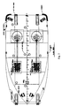
- the powered unit of the integrated towboat system according to a preferred embodiment of the invention will now be explained with reference to figures 1 and 2.
- the powered unit is a unit consisting of two-drive propulsion system, steering system and wireless communication system.
- the system can be operated locally or remotely. When operated remotely, unit becomes part of the main drive unit (the push boat). This allows a totally new method of operating a tow as it incorporates the barges into an integrated power tow.
- This integrated tow is handled as one entity by a unique integrated tow controller that achieves superior steering and propulsion.
- the integrated tow is used to increase back-haul capacity, improve steering through turns, create effective manoeuvrability, and maximise fuel economy.
- the computer may also be configured to select the optimum rpm settings for each of the towboat and bow unit's engines when stopping or accelerating the integrated tow into and out of turns.
- the joystick controls can significantly decrease fuel burn.
- the joystick's computer calculates the required thrust of propellers and thrusters, and the angle of thrusters and rudders. This system is capable of calculating the required thrust and angles as will cause the integrated tow to perform differently on the lower parts of the watercourse.
- the joystick aids the operators in bringing the tow upriver in less time and by burning less fuel.
- the joystick aids the operators in manoeuvring the tow in a manner, which may reduce turn around time.
- the joystick aids the operators to accomplish manoeuvres that were not possible before the integrated tow.
- the maximum steering force that the bow unit exerts upon the integrated tow is typically more than 50% higher than that which a conventionally powered pushboat of equal horsepower will produce.
- the bow unit is able to achieve higher steering forces at smaller thruster angles; therefore, the tow's speed loss due to steering is less.
- the remaining net thrust of the bow unit is greater, and the resultant skidding around a turn is dramatically reduced.
- the integrated tow is able to negotiate turns more quickly and create opportunities to avoid being held up for downstream traffic.
- the benefits realised are a decrease in transit time and a reduction of fuel burned for the upstream leg.
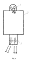
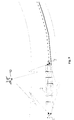
- FIG. 3 illustrates the forces applied to the tow when performing slow turns to port.
- Element 1 in this figure illustrates the new bow-unit with propulsion equipment to be integrated in the tow.
- Elements 2 and 3 illustrates the existing unit as of today, being the payload (barges) and push boat, respectively.
- the word manoeuvring includes all other conditions of operation with and beyond running ahead or astern at a constant speed and on a straight course.
- Reversing the direction of propeller rotation stops a towboat.
- the integrated tow is stopped by reversing direction of the propeller rotation on the towboat and by diverting each outboard propeller race outwards, one port and the other starboard. This is accomplished by flaring independently controlled flanking rudders.
- the bow unit applies powerful braking forces by rotating the two thrusters outwards to a position slightly forward of 90° until the speed drops. Rotating the thrusters to the bow maximises thereafter-thruster braking forces.
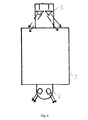
- Figure 4 illustrates the forces to be applied to the tow when performing crash stop at upstream voyage.
- Element 1 is still the new bow-unit to be developed, and the allocation of forces in the integrated system represent a new and improved method of performing emergency crash-stop of a tow of such a size.
- Element 2 represents the actual tow, payload (barges) and element 3 is the push boat.
- the effective thrust generated by the bow unit and towboat is roughly equal to that which is produced by a single towboat having the same horsepower of the integrated tow.
- the integrated tow is able to increase the back haul load above that of a single towboat.
- the barge that is lashed to the bow unit must be an empty in an upstream tow.
- the deep draft of a loaded barge made up directly behind the bow unit will adversely affect the propeller's slipstream and result in a thrust deduction.
- FIG 5 illustrates the use of working tugs 4, 4', any of which can be replaced by an additional powered bow unit of the invention, working the tow to build or break up a tow.
- Elements 4,4' illustrate the working tugs, each manoeuvring a single barge (element 2', 2") relative to the tow. This method offers simplified, more efficient and safer building and breaking up of tows than what is possible with existing methods.
- the integrated tow redefines many of these techniques in a way that applied technology enhance the pilot's ability to perform his job more safely.
- the integrated tow steers better than conventional tows because it places steering and thrust in front of the tow.
- the integrated tow's bow unit utilises two Azimuthing Thrusters to move the tow's pivot point forward and to develop sufficient thrust to push the head of the tow through the turn. This allows the operator to slow steer through more bends, even with larger tow sizes.
- the steering force that the bow unit exerts upon the integrated tow is typically more than 50% higher than that which a conventionally powered pushboat of equal horsepower could produce.
- the integrated tow is able to negotiate more turns using the smaller engines of the bow unit as the tow's primary power, thereby reducing fuel consumption of the tow for the southbound trip...and doing it in less time.
- Many collisions that damage and sink barges are the result of the operator failing to set his tow properly as he attempts to pass under bridge s pans.
- the added steering of the integrated tow and the greater control that is available to the operator will allow him to set up more quickly and make minor corrections as is required. Giving the pilot a more responsive tow is the best way to decrease the risk of collision with bridges.
- Figure 6 illustrates the forces to be applied to the tow when performing crash stop at upstream voyage.
- Element 1 is the new bow-unit to be developed, and the allocation of forces in the integrated system represent a new and improved method of performing emergency crash stop of a tow of such a size.
- Element 2 represents the actual tow, and element 3 is the push boat.
- An integrated tow boat system provides improved system efficiency.
- the Integrated controls will control all thrusters, rudder angles, and engine speeds using only the output that is necessary to maintain optimal control without over correcting the tow.
- This additional control capability enables the tow to be run closer to the bends therein-taking advantage of the stronger currents. The net results will be higher tow speeds without additional fuel burn.
- the Kongsberg Simrad Integrated Towboat Concept consists of 3 equipment modules. Each is a stand-alone system that allows the boat operator to build upon each other to provide the vessel sophistication desired.
- Module #1 constituting the Navigation Bridge Equipment can present the following features:
- Module #2 constituting the Powered Bow Unit can present the following features:
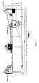
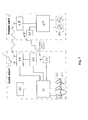
- Figure 7 shows a block diagram illustrating the configuration of the overall system in an embodiment of the invention.
- the push boat unit of an integrated tow system is the existing tug used for pushing the tow up and down the river.
- An exemplary towboat is illustrated in this figure (7).
- this unit typically is equipped with propellers with rudders (element 23), as well as the flanking rudders (element 22). These have been operated manually by the aid of levers, but when part of the integrated towboat system according to the invention, a single joystick will operate these propulsion devices.
- rudders rudders
- flanking rudders element 22
- a single joystick will operate these propulsion devices.
- units to facilitate the wireless communication with, and control of, the new powered bow-unit have been added. All these units together make up the complete integrated towboat system.
- the numbered elements on the push boat illustrated in figure 7 signifies the following units:
- the power unit is the new unit to be integrated to the system.
- this section consists of the following elements: (the numbering refers to the numbering on fig. 7):
- Element 1 is the new powered bow-unit
- 2 is the tow payload including a number of barges
- 3 is the push boat unit
- 20 - 29 are the units making up the automated control system
- 40 illustrates a satellite of a satellite based positioning system used for navigational purposes.
- figure 9 is shown an example of the overall system on voyage on a river, with the main elements 1, 2 and 3 representing the main elements of a tow with the integrated towboat system according to the invention, and element 40 is a satellite of a satellite based positioning system used for navigation.
- Module #3 constituting the Control Telemetry can present the following features:
Landscapes
- Engineering & Computer Science (AREA)
- Chemical & Material Sciences (AREA)
- Combustion & Propulsion (AREA)
- Mechanical Engineering (AREA)
- Ocean & Marine Engineering (AREA)
- Radar, Positioning & Navigation (AREA)
- Remote Sensing (AREA)
- Control Of Position, Course, Altitude, Or Attitude Of Moving Bodies (AREA)
Applications Claiming Priority (2)
| Application Number | Priority Date | Filing Date | Title |
|---|---|---|---|
| NO995477A NO995477D0 (no) | 1999-11-09 | 1999-11-09 | TaubÕtsystem og styringssystem for samme |
| NO995477 | 1999-11-09 |
Publications (2)
| Publication Number | Publication Date |
|---|---|
| EP1099622A2 true EP1099622A2 (de) | 2001-05-16 |
| EP1099622A3 EP1099622A3 (de) | 2003-01-08 |
Family
ID=19903957
Family Applications (1)
| Application Number | Title | Priority Date | Filing Date |
|---|---|---|---|
| EP00610113A Withdrawn EP1099622A3 (de) | 1999-11-09 | 2000-11-09 | Integriertes Schleppsystem |
Country Status (2)
| Country | Link |
|---|---|
| EP (1) | EP1099622A3 (de) |
| NO (1) | NO995477D0 (de) |
Cited By (2)
| Publication number | Priority date | Publication date | Assignee | Title |
|---|---|---|---|---|
| EP1561683A1 (de) * | 2004-02-09 | 2005-08-10 | Wärtsilä Finland Oy | Schubverbandvorrichtung, Barge und Schlepper |
| WO2019083996A1 (en) * | 2017-10-23 | 2019-05-02 | Marine Technologies, Llc | TOWERS AND OPERATIONS |
Family Cites Families (5)
| Publication number | Priority date | Publication date | Assignee | Title |
|---|---|---|---|---|
| US3864662A (en) * | 1973-05-18 | 1975-02-04 | France Etat | Telemetry systems employing active transponders |
| US4063240A (en) * | 1976-08-25 | 1977-12-13 | Sperry Rand Corporation | Electronic docking system |
| DE2655667C3 (de) * | 1976-12-08 | 1980-09-25 | Schottel-Werft Josef Becker Gmbh & Co Kg, 5401 Spay | Wasserfahrzeug |
| GB2173744A (en) * | 1985-04-11 | 1986-10-22 | Michael Thomas Beckett | Sectional vessels |
| US5111763A (en) * | 1989-06-23 | 1992-05-12 | Moerbe Ronald C | Steering unit for barges |
-
1999
- 1999-11-09 NO NO995477A patent/NO995477D0/no unknown
-
2000
- 2000-11-09 EP EP00610113A patent/EP1099622A3/de not_active Withdrawn
Non-Patent Citations (1)
| Title |
|---|
| None |
Cited By (3)
| Publication number | Priority date | Publication date | Assignee | Title |
|---|---|---|---|---|
| EP1561683A1 (de) * | 2004-02-09 | 2005-08-10 | Wärtsilä Finland Oy | Schubverbandvorrichtung, Barge und Schlepper |
| CN100439202C (zh) * | 2004-02-09 | 2008-12-03 | 瓦特西拉芬兰有限公司 | 驳船布置、驳船单元和拖轮单元 |
| WO2019083996A1 (en) * | 2017-10-23 | 2019-05-02 | Marine Technologies, Llc | TOWERS AND OPERATIONS |
Also Published As
| Publication number | Publication date |
|---|---|
| NO995477D0 (no) | 1999-11-09 |
| EP1099622A3 (de) | 2003-01-08 |
Similar Documents
| Publication | Publication Date | Title |
|---|---|---|
| CN112203935B (zh) | 拥挤海域的避航驾船方法及单轴双舵船的避航驾船系统 | |
| CN102171095B (zh) | 操纵杆控制的船用操纵系统 | |
| CN112004741B (zh) | 用于控制拖曳船队的方法 | |
| JP7141777B1 (ja) | 自動着桟機能を有する一軸二舵船 | |
| JP7145542B1 (ja) | 一軸二舵船の操舵角補正機能を有する操舵システム | |
| JP7240739B2 (ja) | 自動航行一軸二舵船 | |
| US20190225307A1 (en) | Towboat and operations thereof | |
| JP2021076537A (ja) | 船舶の着桟支援プログラム、船舶の着桟支援システム、及び船舶の着桟支援システムを装備した船舶 | |
| CN110254648A (zh) | 一种利用dp协助船舶进出港的控制系统 | |
| WO2018008589A1 (ja) | 船舶の操縦システム、船舶、及び船舶の操縦方法 | |
| JPS62279195A (ja) | 総合航法装置 | |
| EP1099622A2 (de) | Integriertes Schleppsystem | |
| JP2023159902A (ja) | 一軸二舵船の船体運動制御装置 | |
| JP7742178B2 (ja) | 2軸4舵船 | |
| JP7328692B2 (ja) | 緊急制御機能を備えた自動航行一軸二舵船 | |
| JPH08207880A (ja) | 第1の船を第2の船に連結する装置 | |
| RU2847373C1 (ru) | Способ управления координированной групповой деятельностью комплексов азимутальных буксиров-автоматов | |
| EP4524023B1 (de) | Schiffsantriebssystem zur bewegung eines wasserfahrzeugs in seitlicher richtung und steuerungsverfahren dafür | |
| EP4154080B1 (de) | Verfahren zur steuerung eines wasserfahrzeugs, steuereinheit und wasserfahrzeug | |
| WO2023048177A1 (ja) | 船舶操縦システム | |
| JPH0966894A (ja) | 高速船等の高速航行体用緊急回避支援方法および装置 | |
| JPS6390498A (ja) | シヤツタ−船舶航行装置 |
Legal Events
| Date | Code | Title | Description |
|---|---|---|---|
| PUAI | Public reference made under article 153(3) epc to a published international application that has entered the european phase |
Free format text: ORIGINAL CODE: 0009012 |
|
| AK | Designated contracting states |
Kind code of ref document: A2 Designated state(s): AT BE CH CY DE DK ES FI FR GB GR IE IT LI LU MC NL PT SE TR |
|
| AX | Request for extension of the european patent |
Free format text: AL;LT;LV;MK;RO;SI |
|
| PUAL | Search report despatched |
Free format text: ORIGINAL CODE: 0009013 |
|
| AK | Designated contracting states |
Kind code of ref document: A3 Designated state(s): AT BE CH CY DE DK ES FI FR GB GR IE IT LI LU MC NL PT SE TR |
|
| AX | Request for extension of the european patent |
Free format text: AL;LT;LV;MK;RO;SI |
|
| AKX | Designation fees paid | ||
| REG | Reference to a national code |
Ref country code: DE Ref legal event code: 8566 |
|
| STAA | Information on the status of an ep patent application or granted ep patent |
Free format text: STATUS: THE APPLICATION IS DEEMED TO BE WITHDRAWN |
|
| 18D | Application deemed to be withdrawn |
Effective date: 20030709 |