EP1099626B1 - Système de sortie de secours arrière et de contrôle pour un aéronef - Google Patents
Système de sortie de secours arrière et de contrôle pour un aéronef Download PDFInfo
- Publication number
- EP1099626B1 EP1099626B1 EP00203468A EP00203468A EP1099626B1 EP 1099626 B1 EP1099626 B1 EP 1099626B1 EP 00203468 A EP00203468 A EP 00203468A EP 00203468 A EP00203468 A EP 00203468A EP 1099626 B1 EP1099626 B1 EP 1099626B1
- Authority
- EP
- European Patent Office
- Prior art keywords
- aircraft
- aft
- cabin
- wing
- panels
- Prior art date
- Legal status (The legal status is an assumption and is not a legal conclusion. Google has not performed a legal analysis and makes no representation as to the accuracy of the status listed.)
- Expired - Lifetime
Links
- 238000003032 molecular docking Methods 0.000 claims 1
- XLYOFNOQVPJJNP-UHFFFAOYSA-N water Substances O XLYOFNOQVPJJNP-UHFFFAOYSA-N 0.000 description 8
- 230000008901 benefit Effects 0.000 description 3
- 210000001015 abdomen Anatomy 0.000 description 2
- 230000009977 dual effect Effects 0.000 description 2
- 238000012986 modification Methods 0.000 description 2
- 230000004048 modification Effects 0.000 description 2
- 230000001174 ascending effect Effects 0.000 description 1
- 239000000446 fuel Substances 0.000 description 1
Images


Classifications
-
- B—PERFORMING OPERATIONS; TRANSPORTING
- B64—AIRCRAFT; AVIATION; COSMONAUTICS
- B64D—EQUIPMENT FOR FITTING IN OR TO AIRCRAFT; FLIGHT SUITS; PARACHUTES; ARRANGEMENT OR MOUNTING OF POWER PLANTS OR PROPULSION TRANSMISSIONS IN AIRCRAFT
- B64D11/00—Passenger or crew accommodation; Flight-deck installations not otherwise provided for
-
- B—PERFORMING OPERATIONS; TRANSPORTING
- B64—AIRCRAFT; AVIATION; COSMONAUTICS
- B64C—AEROPLANES; HELICOPTERS
- B64C1/00—Fuselages; Constructional features common to fuselages, wings, stabilising surfaces or the like
- B64C1/22—Other structures integral with fuselages to facilitate loading, e.g. cargo bays, cranes
-
- B—PERFORMING OPERATIONS; TRANSPORTING
- B64—AIRCRAFT; AVIATION; COSMONAUTICS
- B64C—AEROPLANES; HELICOPTERS
- B64C3/00—Wings
-
- B—PERFORMING OPERATIONS; TRANSPORTING
- B64—AIRCRAFT; AVIATION; COSMONAUTICS
- B64C—AEROPLANES; HELICOPTERS
- B64C39/00—Aircraft not otherwise provided for
- B64C39/10—All-wing aircraft
-
- B—PERFORMING OPERATIONS; TRANSPORTING
- B64—AIRCRAFT; AVIATION; COSMONAUTICS
- B64C—AEROPLANES; HELICOPTERS
- B64C39/00—Aircraft not otherwise provided for
- B64C39/10—All-wing aircraft
- B64C2039/105—All-wing aircraft of blended wing body type
Definitions
- the present invention relates to aircraft of the type having a cabin defined within a wing of the aircraft. More particularly, the invention relates to an aft egress device providing access to the cabin of such an aircraft and to an aircraft having such an aft egress device.
- aircraft designs are being contemplated which would enable capacity to be increased substantially above the largest aircraft that are currently available.
- aircraft configurations being studied are aircraft having the passenger cabin and/or cargo compartments within the wing rather than (or in addition to) within the fuselage.
- Such aircraft are referred to herein as "blended wing-body" aircraft, but it will be understood that the invention is not limited to any particular aircraft configuration and applies to any aircraft having a cabin or compartment within a wing.
- the document US-A-5 893 535 discloses an aircraft comprising a wing having upper and lower aerodynamic surfaces extending between a leading edge and a trailing edge of the wing; a cabin defined between the upper and lower surfaces of the wing and having an aft end proximate the trailing edge of the wing (see Figure 6); and a generally wedge-shaped aft egress device forming at least a portion of the trailing edge of the wing, whereby access can be had to the cabin through the aft egress device.
- US-A-2 942 813 discloses a combined speed brake, escape hatch and baggage access door for an aircraft.
- the aircraft according to claim 1 provides an aircraft having an aft egress device which provides access to the cabin through a trailing edge portion of the wing.
- the trailing edge of the wing is usually devoted to variable control surfaces such as pitch controllers, and may also accommodate engines, hydraulic systems, and other systems, the invention nevertheless enables an aft egress to be located in the trailing edge of the wing.
- the aft egress device performs dual functions of providing access to the cabin and serving as a variable control surface for the aircraft.
- the invention meets the aforementioned needs by providing an aircraft having one or more aft egress devices which can serve as additional exits for emergency evacuation of the aircraft, and can also serve as access passages for service crews to service the aircraft from the rear, thus allowing passengers to board the aircraft through forward doors while service crew members simultaneously service the aircraft.
- the aft egress device also serves as a variable control surface
- the invention enables aft access passages to be provided without conflicting with the requirement of providing control surfaces for the aircraft.
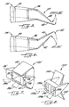
- an aircraft 20 is schematically shown in sectioned side elevation in which an aft egress device 22 in accordance with one embodiment of the invention forms a wedge-shaped trailing edge portion of the wing 24.
- the aircraft 20 is of the blended wing-body (also known as "flying wing") type of aircraft in which a cabin 26 is defined within the interior of the wing between the upper surface 28 and the lower surface 30 of the wing.
- the aft end of the cabin 26 is bounded by a rear spar 32 which includes an access opening 34 through which access can be had to the cabin.
- the aircraft also includes an auxiliary spar 36 aft of the rear spar 32, the auxiliary spar serving as a support structure for the aft egress device 22.
- the auxiliary spar 36 also includes an access opening 38 for access to the cabin, as further described below.
- FIGS. 2-6 depict the aft egress device 22 in more detail and illustrate the device in various positions.
- the aft egress device 22 includes an upper panel 40 which is pivotally mounted at its forward end to the auxiliary spar 36, such as by means of a hinged connection, and a lower panel 42 which likewise is pivotally mounted at its forward end to the auxiliary spar, also typically by means of a hinged connection.
- the forward ends of the panels 40 and 42 are vertically spaced apart and are generally aligned with the upper and lower ends of the access opening 38 in the auxiliary spar 36.
- FIG. 2 depicts the aft egress device in a closed condition in which the upper and lower panels 40 and 42 converge toward their aft ends to form a wedge-shaped trailing edge portion of the wing 24.
- the upper panel 40 forms an extension of the upper surface 28 of the wing
- the lower panel 42 forms an extension of the lower surface 30 of the wing.
- the panels 40 and 42 close the access opening 38 when they are in the closed positions as shown in FIG. 2.
- FIG. 3 shows the aft egress device 22 in an open service position enabling service crew members to enter through the access opening 38 and through the opening 34 in the rear spar 32 into the cabin 26 (FIG. 1).
- the upper panel 40 is pivoted upward and the lower panel 42 is pivoted downward into a generally horizontal position.
- the upper and/or lower panels are pivoted by means of actuators or the like, as described below in conjunction with the embodiment of FIG. 9.
- the lower panel 42 in this position serves as a ramp for loading and unloading persons and cargo into and out of the cabin.
- a passage 44 is created between the panels 40 and 42 for access to the cabin.
- FIG. 4 shows the aft egress device 22 in an open emergency evacuation position enabling persons in the cabin to exit the aircraft through the egress device and reach the ground.
- the lower panel 42 is pivoted downward so as to extend down from the wing 24 to the ground (or the water in the case of a water landing). In this position, the lower panel 42 serves as an emergency slide.
- the invention enables the aft egress device 22 to perform dual functions of providing an access passage for access to and evacuation of the cabin, and also providing aerodynamic control to the aircraft.
- FIG. 5 shows the aft egress device 22 in a flap-down configuration for providing aerodynamic control to the aircraft.
- the upper panel 40 and lower panel 42 are pivoted generally in unison so as to angle downward.
- FIG. 6 shows the aft egress device 22 in a flap-up configuration with the panels 40 and 42 pivoted generally in unison so as to angle upward.
- FIGS. 7 and 8 are perspective views of two alternative embodiments of aft egress devices in accordance with the invention.
- an aft egress device 22' is shown in which a single double-wide access opening 38' is formed in an auxiliary spar 36' so that two side-by-side aisles 39a and 39b leading from the cabin of the aircraft can feed into the egress device.
- aft egress device 22' is shown in which a single double-wide access opening 38' is formed in an auxiliary spar 36' so that two side-by-side aisles 39a and 39b leading from the cabin of the aircraft can feed into the egress device.
- one of the aisles 39a may lead from the upper deck while the other aisle 39b leads from the lower deck.
- Pivotal movement of the upper panel 40' is effected by an actuator 46 connected at one end to the fixed wing structure and connected at the other end to the upper panel 40'.
- Pivotal movement of the lower panel 42' is effected by a separate actuator 48 similarly connected between the wing structure and the lower panel.
- the upper and lower panels may be moved independently of each other.
- the upper and lower panels 40' and 42' may be pivoted away from each other as shown for aerodynamic control purposes such as aerodynamic braking on a landing roll.
- FIG. 8 shows an alternative embodiment of an aft egress device 122 in which two side-by-side single-wide access openings 138a and 138b are formed in the auxiliary spar 136 so that two aisles 139a and 139b leading from the aircraft cabin can be fed to the egress device.
- FIG. 8 also illustrates that in some cases it is desirable to provide the upper panel 140 and lower panel 142 with the capability of rotating to generally vertical positions (or more preferably past vertical) so as not to interfere with ground service vehicles which may dock with the passage in the aft egress device 122.
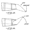
- FIGS. 9-14 depict an aft egress device 222 in which the lower panel 242 is pivotally connected at its forward end 244 to the wing structure, and the upper panel 240 is pivotally connected at its forward end 246 to the lower panel 242 via a pair of side walls 248 which are fixed to the lower panel 242 along each of the opposite sides thereof.
- the side walls 248 extend upward from the lower panel 242 and terminate at upper ends 250 adjacent the upper surface 228 of the wing.
- the upper panel 240 is pivotally connected to the upper ends 250 of the side walls 248.
- An actuator 252 is connected between the wing structure and each of the side walls 248 for effecting pivotal movement of the lower panel 242.
- the aft egress device 222 includes a latch 254 comprising cooperative latch members 256 and 258 attached to the lower panel 242 and upper panel 240, respectively. When the latch members 256 and 258 are engaged with each other, the upper panel 240 is slaved to the lower panel 242 (as shown in phantom lines in FIG.
- the aft egress device 222 also includes a spring device 260 connected between the lower panel 242 and the upper panel 240 for biasing the panels away from each other. When the latch members 256 and 258 are disengaged from each other, the spring device 260 pivotally moves the upper panel 240 upward away from the lower panel 242 so as to create a passage 262 between the panels for access to the cabin of the aircraft.
- the spring device 260 is illustrated as being a coil spring, it will be understood that other types of spring devices such as pneumatic devices or the like may be used instead of or in addition to a coil spring.
- FIGS. 10-14 depict the aft egress device 222 in various positions corresponding to the positions of the aft egress device 22 shown in FIGS. 2-6, respectively.
- the upper panel 240 is unlatched from the lower panel 242 and the lower panel 242 is pivoted into a generally horizontal position, as shown in FIG. 11, so that the lower panel serves as a ramp for loading and unloading.
- the panels are unlatched from each other and the lower panel 242 is pivoted downward to intersect the ground (or the water in the case of a water landing) so as to serve as an emergency slide, as shown in FIG. 12.
- FIGS. 13 and 14 show the aft egress device 222 in flap-down and flap-up positions for effecting aerodynamic control of the aircraft.
- the invention provides unique aft egress devices enabling access to and egress from a cabin in an aircraft wing through an aft end of the cabin and through a trailing edge portion of the wing. Locating the egress device at the wing trailing edge enables the device to be used for emergency evacuation in a variety of circumstances including water landings, belly landings (i.e., all landing gear up), and various combinations of landing gear failures.
- the aft egress devices of the invention can also serve as access passages for service crews to service the aircraft from the rear, thus allowing passengers to board the aircraft through forward doors while service crew members simultaneously service the aircraft from the rear. Additionally, where the aft egress devices also serve as variable control surfaces, the invention enables aft access passages to be provided without conflicting with the requirement of providing trailing edge control surfaces for the aircraft.
- the aft egress device 222 is illustrated and described as having the lower panel 242 connected to the actuators 252 and the upper panel 240 slaved to the lower panel 242; however, it will be recognized that the upper panel 240 may be connected to the actuators 252 and the lower panel 242 may be slaved to the upper panel.
- the upper and lower panels are described as being pivotally mounted to auxiliary spar 36, the upper and lower panels can be mounted to other portions of the wing such that the resulting aft egress device forms a portion of the trailing edge of the wing.
Landscapes
- Engineering & Computer Science (AREA)
- Aviation & Aerospace Engineering (AREA)
- Mechanical Engineering (AREA)
- Tires In General (AREA)
- Body Structure For Vehicles (AREA)
Claims (16)
- Aéronef, comprenant :une aile ayant des surfaces aérodynamiques supérieure et inférieure qui s'étendent entre un bord d'attaque et un bord de fuite de l'aile,une cabine délimitée entre les surfaces supérieure et inférieure de l'aile et ayant une extrémité arrière proche du bord de fuite de l'aile, la cabine délimitant une ouverture à son extrémité arrière pour l'entrée dans la cabine et la sortie de celle-ci, etun dispositif de contrôle et de sortie arrière ayant une forme générale de coin, formant une partie au moins du bord de fuite de l'aile et pouvant pivoter comme un tout par rapport au reste de l'aile pour être utilisé comme gouverne de bord de fuite de l'aile, le dispositif de contrôle et de sortie arrière comprenant des panneaux supérieur et inférieur et un système à organe de manoeuvre raccordé aux panneaux et destiné à faire pivoter les panneaux à la fois dans le même sens et en sens opposés, le système à organe de manoeuvre étant destiné à faire pivoter l'un au moins des panneaux afin qu'il s'écarte de l'autre pour la création entre eux d'un passage relié à l'ouverture de la cabine, si bien qu'un accès à la cabine peut être obtenu par l'intermédiaire du dispositif de contrôle et de sortie arrière.
- Aéronef selon la revendication 1, dans lequel les panneaux supérieur et inférieur sont tous deux montés sur l'aile.
- Aéronef selon la revendication 1 ou 2, dans lequel l'un des panneaux est monté sur l'aile et l'autre panneau est monté sur le premier panneau.
- Aéronef selon la revendication 3, dans lequel le système à organe de manoeuvre comprend un premier organe de manoeuvre raccordé au premier panneau afin que le dispositif de contrôle et de sortie arrière pivote comme un tout lorsqu'il est utilisé comme gouverne, et un second organe de manoeuvre raccordé entre les panneaux et destiné à faire pivoter les panneaux afin qu'ils s'écartent l'un de l'autre et donnent accès à la cabine.
- Aéronef selon la revendication 4, dans lequel le second organe de manoeuvre comporte un ressort.
- Aéronef selon la revendication 5, comprenant en outre un verrou destiné à verrouiller les panneaux l'un sur l'autre lorsque le dispositif de contrôle et de sortie arrière est utilisé comme gouverne et à déverrouiller les panneaux pour leur permettre de pivoter à distance l'un de l'autre pour donner accès à la cabine.
- Aéronef selon l'une quelconque des revendications 1 à 6, dans lequel les panneaux peuvent s'écarter l'un de l'autre par pivotement à des orientations pratiquement verticales, afin, qu'ils ne constituent pas d'obstacle lorsque des véhicules terrestres viennent en appui contre le passage du dispositif de contrôle et de sortie arrière.
- Aéronef selon l'une quelconque des revendications 1 à 7, dans lequel le panneau inférieur peut pivoter vers le bas en s'écartant du panneau supérieur avec une orientation inclinée afin qu'il soit utilisé comme rampe.
- Aéronef selon l'une quelconque des revendications 1 à 8, dans lequel les panneaux sont montés de façon pivotante sur un longeron de l'aile.
- Aéronef selon la revendication 9, dans lequel l'extrémité arrière de la cabine est délimitée par un longeron arrière de l'aile, et le longeron sur lequel les panneaux sont montés est un longeron auxiliaire disposé en arrière du longeron arrière.
- Aéronef selon la revendication 10, dans lequel l'ouverture débouchant dans la cabine est délimitée dans le longeron arrière, et le longeron auxiliaire délimite aussi une ouverture pour l'accès à la cabine.
- Aéronef selon l'une quelconque des revendications 1 à 11, dans lequel le dispositif de contrôle et de sortie arrière peut pivoter en position de volet tourné vers le haut et vers le bas.
- Aéronef selon l'une quelconque des revendications 1 à 12, dans lequel la cabine a deux allées disposées côte à côte et rejoignant l'ouverture formée à l'extrémité arrière de la cabine, et le passage formé dans le dispositif de contrôle et de sortie arrière est un passage de double largeur raccordant les deux allées.
- Aéronef selon la revendication 13, dans lequel les panneaux sont montés de façon pivotante sur un longeron auxiliaire de l'aile et le passage dans le dispositif de contrôle et de sortie arrière est relié à l'ouverture de double largeur formée dans le longeron auxiliaire aligné sur les deux allées de la cabine.
- Aéronef selon la revendication 14, dans lequel les panneaux sont montés de façon pivotante sur un longeron auxiliaire de l'aile et le passage formé dans le dispositif de contrôle et de sortie arrière est raccordé à une paire d'ouvertures placées côte à côte dans le longeron auxiliaire et alignées respectivement sur les deux allées de la cabine.
- Aéronef selon l'une quelconque des revendications 1 à 15, dans lequel le système à organe de manoeuvre comprend des organes de manoeuvre pouvant fonctionner indépendamment et raccordés aux panneaux supérieur et inférieur afin que chaque panneau puisse pivoter indépendamment de l'autre.
Applications Claiming Priority (2)
| Application Number | Priority Date | Filing Date | Title |
|---|---|---|---|
| US09/438,090 US6382562B1 (en) | 1999-11-10 | 1999-11-10 | AFT egress and control device for an aircraft |
| US438090 | 1999-11-10 |
Publications (2)
| Publication Number | Publication Date |
|---|---|
| EP1099626A1 EP1099626A1 (fr) | 2001-05-16 |
| EP1099626B1 true EP1099626B1 (fr) | 2003-04-02 |
Family
ID=23739171
Family Applications (1)
| Application Number | Title | Priority Date | Filing Date |
|---|---|---|---|
| EP00203468A Expired - Lifetime EP1099626B1 (fr) | 1999-11-10 | 2000-10-06 | Système de sortie de secours arrière et de contrôle pour un aéronef |
Country Status (3)
| Country | Link |
|---|---|
| US (1) | US6382562B1 (fr) |
| EP (1) | EP1099626B1 (fr) |
| DE (1) | DE60001897T2 (fr) |
Families Citing this family (13)
| Publication number | Priority date | Publication date | Assignee | Title |
|---|---|---|---|---|
| FR2817237B1 (fr) * | 2000-11-28 | 2003-02-28 | Eads Airbus Sa | Dispositif d'acces a bord pour aeronef et aile volante equipee d'un tel dispositif |
| US7093798B2 (en) * | 2004-01-30 | 2006-08-22 | The Boeing Company | Transformable airplane |
| DE102004049504A1 (de) * | 2004-10-11 | 2006-04-13 | Airbus Deutschland Gmbh | Flugzeugflügel, Verfahren zum Betreiben eines Flugzeugflügels und Verwendung einer schwenkbaren Hinterkante an einem Hauptflügel eines Flugzeugflügels zum Justieren der Form und Breite eines Luftspalts |
| DE102005044535B3 (de) * | 2005-09-17 | 2007-06-14 | Airbus Deutschland Gmbh | Einrichtung zur Not-Evakuierung, insbesondere für ein Nurflügel-Flugzeug |
| US8366050B2 (en) | 2009-11-21 | 2013-02-05 | The Boeing Company | Blended wing body cargo airplane |
| DE102014201040A1 (de) * | 2014-01-21 | 2015-07-23 | Airbus Operations Gmbh | Luftfahrzeug |
| US10696378B2 (en) * | 2017-10-20 | 2020-06-30 | The Boeing Company | Cargo door assembly for vehicle |
| EP3587261B1 (fr) * | 2018-06-22 | 2021-04-14 | Bombardier Inc. | Aéronef à aile volante |
| US10919631B2 (en) * | 2018-10-29 | 2021-02-16 | Safran Cabin Inc. | Aircraft with multiple doors and multiple zones |
| US11034452B2 (en) * | 2018-10-29 | 2021-06-15 | Safran Cabin Inc. | Aircraft with staggered seating arrangement |
| US10661879B2 (en) * | 2018-10-29 | 2020-05-26 | Safran Cabin Inc. | Aircraft with selective cargo area access |
| US20260062133A1 (en) * | 2024-09-04 | 2026-03-05 | General Electric Company | Blended wing aircraft |
| US12448134B1 (en) | 2025-01-15 | 2025-10-21 | General Electric Company | Blended wing aircraft |
Family Cites Families (20)
| Publication number | Priority date | Publication date | Assignee | Title |
|---|---|---|---|---|
| US1854444A (en) * | 1929-09-03 | 1932-04-19 | George E Barnhart | Airplane wing construction |
| US1916475A (en) * | 1931-06-16 | 1933-07-04 | Randolph F Hall | Airplane |
| US1987050A (en) | 1933-02-23 | 1935-01-08 | Burnelli Aircraft Ltd | Tailless airplane |
| US2376780A (en) * | 1942-01-26 | 1945-05-22 | Oades J Kenyon | Tail structure for aircraet |
| US2323279A (en) | 1942-08-20 | 1943-06-29 | Glenn L Martin Co | Cargo landplane |
| US2547811A (en) * | 1945-09-25 | 1951-04-03 | Vincent J Burnelli | Rear doorway for airfoil fuselages |
| US2616639A (en) * | 1948-10-26 | 1952-11-04 | Vincent J Burnelli | Cargo air transport |
| US2650780A (en) | 1949-04-02 | 1953-09-01 | Northrop Aircraft Inc | All-wing aircraft |
| US2759691A (en) | 1953-08-04 | 1956-08-21 | Fairchild Engine & Airplane | Aircraft cargo loading doors |
| US2926869A (en) * | 1956-10-01 | 1960-03-01 | John J Sullivan | Vertical and horizontal flight amphibious aircraft |
| US2942813A (en) | 1958-02-14 | 1960-06-28 | Lockheed Aircraft Corp | Combined speed brake, escape hatch and baggage access door for aircraft |
| US3216373A (en) * | 1963-12-16 | 1965-11-09 | Pullman Inc | Bridge plate counterbalance device |
| US3486719A (en) | 1967-12-04 | 1969-12-30 | Aereon Corp | Airship |
| US3544046A (en) | 1968-08-01 | 1970-12-01 | Alexei Yakovlevich Belolipetsk | Device for opening and closing hatch of airborne craft |
| US4140291A (en) | 1977-10-13 | 1979-02-20 | The United States Of America As Represented By The Secretary Of The Air Force | Ramp toe stowage system |
| US4167258A (en) | 1978-03-24 | 1979-09-11 | Lockheed Corporation | Aft cargo door for aircraft |
| US4566657A (en) * | 1979-05-21 | 1986-01-28 | Grow Harlow B | Span loaded flying wing control |
| US4449679A (en) | 1982-03-05 | 1984-05-22 | Fairchild Industries, Inc. | Multi role aircraft |
| EP0271197B1 (fr) | 1986-10-31 | 1991-02-27 | British Aerospace Public Limited Company | Agencement de porte pour avion |
| US5893535A (en) | 1997-06-19 | 1999-04-13 | Mcdonnell Douglas Corporation | Rib for blended wing-body aircraft |
-
1999
- 1999-11-10 US US09/438,090 patent/US6382562B1/en not_active Expired - Lifetime
-
2000
- 2000-10-06 EP EP00203468A patent/EP1099626B1/fr not_active Expired - Lifetime
- 2000-10-06 DE DE60001897T patent/DE60001897T2/de not_active Expired - Lifetime
Also Published As
| Publication number | Publication date |
|---|---|
| DE60001897D1 (de) | 2003-05-08 |
| US6382562B1 (en) | 2002-05-07 |
| EP1099626A1 (fr) | 2001-05-16 |
| DE60001897T2 (de) | 2003-11-06 |
Similar Documents
| Publication | Publication Date | Title |
|---|---|---|
| US6834833B2 (en) | Twin aisle small airplane | |
| EP2512921B1 (fr) | Station de repos d'équipage d'avion commercial à structure à pression de petit diamètre | |
| US6851650B2 (en) | Tri-body aircraft and methods for their manufacture | |
| EP0987177B1 (fr) | Aéronef à double cabine supérieure | |
| EP1099626B1 (fr) | Système de sortie de secours arrière et de contrôle pour un aéronef | |
| US7644888B2 (en) | High-speed aircraft and methods for their manufacture | |
| US9108719B2 (en) | Aircraft with AFT split-level multi-deck fusealge | |
| US8398022B2 (en) | Wide body aircraft architecture | |
| CA2363194C (fr) | Dispositif d'acces a bord pour aeronef et aile volante equipee d'un tel dispositif | |
| EP1413513A2 (fr) | Aéronef avec une soute inférieure polyvalente et procédés de fabrication associés | |
| EP2840023B1 (fr) | Aéronef avec fuselage arrière multi-étages à deux niveaux | |
| US20040245375A1 (en) | Integrated high-speed aircraft and associated methods of manufacture | |
| US7156345B2 (en) | Modular overhead stowage bin systems and associated methods | |
| US10589836B2 (en) | Split level forward double deck airliner | |
| US7717372B2 (en) | Reduced-perimeter aircraft | |
| US20180281934A1 (en) | Front landing gear of reduced height and aircraft, in particular a flying wing, equipped with such a front landing gear | |
| US9452817B1 (en) | Aircraft having split level cabin floors | |
| US20250304254A1 (en) | Emergency oxygen systems for internal cabins of aircraft | |
| US8720820B2 (en) | Aircraft having multiple seating configurations and associated systems and methods | |
| EP3263457B1 (fr) | Avion à double cabine avant à niveau séparé | |
| EP4155207A1 (fr) | Ensembles de compartiments de rangement pour cabines internes d'aéronef | |
| US20070278346A1 (en) | Aircraft cabin configuration | |
| GB2500767A (en) | System for loading passengers into a vehicle | |
| Beach | Designing the Lockheed L-1011 to Meet Airline Needs Beyond 1970 |
Legal Events
| Date | Code | Title | Description |
|---|---|---|---|
| PUAI | Public reference made under article 153(3) epc to a published international application that has entered the european phase |
Free format text: ORIGINAL CODE: 0009012 |
|
| AK | Designated contracting states |
Kind code of ref document: A1 Designated state(s): DE FR GB |
|
| AX | Request for extension of the european patent |
Free format text: AL;LT;LV;MK;RO;SI |
|
| 17P | Request for examination filed |
Effective date: 20011011 |
|
| 17Q | First examination report despatched |
Effective date: 20011207 |
|
| AKX | Designation fees paid |
Free format text: DE FR GB |
|
| GRAH | Despatch of communication of intention to grant a patent |
Free format text: ORIGINAL CODE: EPIDOS IGRA |
|
| GRAH | Despatch of communication of intention to grant a patent |
Free format text: ORIGINAL CODE: EPIDOS IGRA |
|
| GRAA | (expected) grant |
Free format text: ORIGINAL CODE: 0009210 |
|
| AK | Designated contracting states |
Designated state(s): DE FR GB |
|
| REG | Reference to a national code |
Ref country code: GB Ref legal event code: FG4D |
|
| REF | Corresponds to: |
Ref document number: 60001897 Country of ref document: DE Date of ref document: 20030508 Kind code of ref document: P |
|
| ET | Fr: translation filed | ||
| PLBE | No opposition filed within time limit |
Free format text: ORIGINAL CODE: 0009261 |
|
| STAA | Information on the status of an ep patent application or granted ep patent |
Free format text: STATUS: NO OPPOSITION FILED WITHIN TIME LIMIT |
|
| 26N | No opposition filed |
Effective date: 20040105 |
|
| REG | Reference to a national code |
Ref country code: FR Ref legal event code: PLFP Year of fee payment: 16 |
|
| REG | Reference to a national code |
Ref country code: FR Ref legal event code: PLFP Year of fee payment: 17 |
|
| REG | Reference to a national code |
Ref country code: FR Ref legal event code: PLFP Year of fee payment: 18 |
|
| REG | Reference to a national code |
Ref country code: FR Ref legal event code: PLFP Year of fee payment: 19 |
|
| PGFP | Annual fee paid to national office [announced via postgrant information from national office to epo] |
Ref country code: DE Payment date: 20191029 Year of fee payment: 20 |
|
| PGFP | Annual fee paid to national office [announced via postgrant information from national office to epo] |
Ref country code: FR Payment date: 20191025 Year of fee payment: 20 |
|
| PGFP | Annual fee paid to national office [announced via postgrant information from national office to epo] |
Ref country code: GB Payment date: 20191028 Year of fee payment: 20 |
|
| REG | Reference to a national code |
Ref country code: DE Ref legal event code: R071 Ref document number: 60001897 Country of ref document: DE |
|
| REG | Reference to a national code |
Ref country code: GB Ref legal event code: PE20 Expiry date: 20201005 |
|
| PG25 | Lapsed in a contracting state [announced via postgrant information from national office to epo] |
Ref country code: GB Free format text: LAPSE BECAUSE OF EXPIRATION OF PROTECTION Effective date: 20201005 |