EP1099802A2 - Positions- und Orientierungsgeber für eine Baumaschine - Google Patents
Positions- und Orientierungsgeber für eine Baumaschine Download PDFInfo
- Publication number
- EP1099802A2 EP1099802A2 EP00650188A EP00650188A EP1099802A2 EP 1099802 A2 EP1099802 A2 EP 1099802A2 EP 00650188 A EP00650188 A EP 00650188A EP 00650188 A EP00650188 A EP 00650188A EP 1099802 A2 EP1099802 A2 EP 1099802A2
- Authority
- EP
- European Patent Office
- Prior art keywords
- fiber
- construction apparatus
- optic bundle
- base
- monitoring
- Prior art date
- Legal status (The legal status is an assumption and is not a legal conclusion. Google has not performed a legal analysis and makes no representation as to the accuracy of the status listed.)
- Withdrawn
Links
Images

Classifications
-
- G—PHYSICS
- G01—MEASURING; TESTING
- G01D—MEASURING NOT SPECIALLY ADAPTED FOR A SPECIFIC VARIABLE; ARRANGEMENTS FOR MEASURING TWO OR MORE VARIABLES NOT COVERED IN A SINGLE OTHER SUBCLASS; TARIFF METERING APPARATUS; MEASURING OR TESTING NOT OTHERWISE PROVIDED FOR
- G01D5/00—Mechanical means for transferring the output of a sensing member; Means for converting the output of a sensing member to another variable where the form or nature of the sensing member does not constrain the means for converting; Transducers not specially adapted for a specific variable
- G01D5/26—Mechanical means for transferring the output of a sensing member; Means for converting the output of a sensing member to another variable where the form or nature of the sensing member does not constrain the means for converting; Transducers not specially adapted for a specific variable characterised by optical transfer means, i.e. using infrared, visible, or ultraviolet light
- G01D5/268—Mechanical means for transferring the output of a sensing member; Means for converting the output of a sensing member to another variable where the form or nature of the sensing member does not constrain the means for converting; Transducers not specially adapted for a specific variable characterised by optical transfer means, i.e. using infrared, visible, or ultraviolet light using optical fibres
-
- E—FIXED CONSTRUCTIONS
- E02—HYDRAULIC ENGINEERING; FOUNDATIONS; SOIL SHIFTING
- E02F—DREDGING; SOIL-SHIFTING
- E02F3/00—Dredgers; Soil-shifting machines
- E02F3/04—Dredgers; Soil-shifting machines mechanically-driven
- E02F3/28—Dredgers; Soil-shifting machines mechanically-driven with digging tools mounted on a dipper- or bucket-arm, i.e. there is either one arm or a pair of arms, e.g. dippers, buckets
- E02F3/36—Component parts
- E02F3/42—Drives for dippers, buckets, dipper-arms or bucket-arms
- E02F3/43—Control of dipper or bucket position; Control of sequence of drive operations
- E02F3/431—Control of dipper or bucket position; Control of sequence of drive operations for bucket-arms, front-end loaders, dumpers or the like
-
- E—FIXED CONSTRUCTIONS
- E02—HYDRAULIC ENGINEERING; FOUNDATIONS; SOIL SHIFTING
- E02F—DREDGING; SOIL-SHIFTING
- E02F3/00—Dredgers; Soil-shifting machines
- E02F3/04—Dredgers; Soil-shifting machines mechanically-driven
- E02F3/28—Dredgers; Soil-shifting machines mechanically-driven with digging tools mounted on a dipper- or bucket-arm, i.e. there is either one arm or a pair of arms, e.g. dippers, buckets
- E02F3/36—Component parts
- E02F3/42—Drives for dippers, buckets, dipper-arms or bucket-arms
- E02F3/43—Control of dipper or bucket position; Control of sequence of drive operations
- E02F3/435—Control of dipper or bucket position; Control of sequence of drive operations for dipper-arms, backhoes or the like
-
- E—FIXED CONSTRUCTIONS
- E02—HYDRAULIC ENGINEERING; FOUNDATIONS; SOIL SHIFTING
- E02F—DREDGING; SOIL-SHIFTING
- E02F3/00—Dredgers; Soil-shifting machines
- E02F3/04—Dredgers; Soil-shifting machines mechanically-driven
- E02F3/76—Graders, bulldozers, or the like with scraper plates or ploughshare-like elements; Levelling scarifying devices
- E02F3/80—Component parts
- E02F3/84—Drives or control devices therefor, e.g. hydraulic drive systems
- E02F3/844—Drives or control devices therefor, e.g. hydraulic drive systems for positioning the blade, e.g. hydraulically
-
- E—FIXED CONSTRUCTIONS
- E02—HYDRAULIC ENGINEERING; FOUNDATIONS; SOIL SHIFTING
- E02F—DREDGING; SOIL-SHIFTING
- E02F9/00—Component parts of dredgers or soil-shifting machines, not restricted to one of the kinds covered by groups E02F3/00 - E02F7/00
- E02F9/26—Indicating devices
- E02F9/264—Sensors and their calibration for indicating the position of the work tool
-
- G—PHYSICS
- G02—OPTICS
- G02B—OPTICAL ELEMENTS, SYSTEMS OR APPARATUS
- G02B6/00—Light guides; Structural details of arrangements comprising light guides and other optical elements, e.g. couplings
- G02B6/02—Optical fibres with cladding with or without a coating
- G02B6/02057—Optical fibres with cladding with or without a coating comprising gratings
Definitions
- This invention relates generally to construction equipment and, more particularly, to control systems for monitoring the position of construction equipment members and, optionally, controlling such members in a closed loop control.
- the invention is applicable to excavators, graders, trenchers, and the like.
- a feedback control system can be established in order to drive the member to a desired position, such as disclosed in commonly assigned United States Patent 4,829,418, the disclosure of which is hereby incorporated herein by reference.
- Monitoring the position of the member has proven difficult.
- the member is located at the end of a series of articulated members, such as the bucket on an excavator is rotatably connected to a stick which is rotatably connected to a boom which is rotatably connected to a frame or cab member.
- the frame or cab member is rotatably connected to a propulsion unit, such as a set of caterpillars defining a crawler.
- a propulsion unit such as a set of caterpillars defining a crawler.
- a propulsion unit such as a set of caterpillars defining a crawler.
- Each of the members is monitored by some form of transducer, such as a rotary encoder, verticality sensor, or the like.
- Each sensor output is wired back to a control position centrally, such as at the frame member.
- a control processes the outputs of the various sensors and produces a value representative of the position of the bucket teeth at any one time.
- Each of the sensors must be supplied with electrical power and an output fed back to a central control. This requires extensive wiring, as well as the necessity for proper positioning and calibrating of each sensor. Each of the sensors is subject to physical damage as well as various forms of interference, such as electromagnetic interference. In order to determine the position of the monitored member, it is first necessary to read and combine the outputs of numerous sensors. The sensors often need to be integrated in order to arrive at the desired parameter. All of this increases the complexity of the apparatus for assembling and operating. Furthermore, the results are not always satisfactory in the field.
- the present invention is directed to a construction apparatus including a base, a member supported by the base through an articulated support and a control.
- the control monitors the orientation and/or position of the member.
- the control includes a fiber-optic sensor producing a signal proportional to curvature or displacement of a fiber-optic bundle.
- the invention advantageously allows the monitoring of the member, which may be a construction implement, such as an excavator bucket, a grader blade, or the like, while avoiding many of the problems of the prior art.
- a control unit in the cab, or the like may monitor the member without the requirement for supplying electrical energy to the member itself.
- the output of the control is a signal proportional to the measured position and/or orientation of the member without the necessity for combining the outputs of numerous sensors and integrating the resultant signal. Furthermore, the control is substantially immune to electromagnetic interference and other environmental degradation at the job site and can be used to field-upgrade existing equipment.
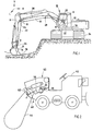
- a construction apparatus in the form of an excavator 10 includes a base 12 and a construction implement in the form of a bucket 14 having digging teeth 16.
- Bucket 14 is connected with base 12 through an articulated support in the form of a boom 18 pivotally connected with base 12 at a pivot 20 and a stick 22 pivotally connected with boom 18 at a pivot 24.
- Bucket 14 is pivotally connected with stick 22 at pivot 26.
- a control 28 monitors the position and/or orientation of bucket 14.
- Control 28 includes a fiber-optic bundle 30 extending from an electronic control assembly 32 positioned at base 12 and extending to bucket 14.
- Control 28 produces a parameter as monitored by electronic control 32 that directly represents the position and/or orientation of bucket 14.
- Fiber-optic bundle 30 which may be positioned within a flexible conduit, such as plastic conduit, aluminum conduit, steel conduit, or the like, may be registered with pivots 20, 24 and 26 by registration members R located at the excavator, and corresponding registration members are on the fiber-optic bundle 30. This provides precise positioning between the fiber-optic bundle and each pivot 20, 24 and 26.
- excavator 10 includes a crawler, or a caterpillar, 34 that pivotally supports base 12 at a joint 36. Another control 28 could be positioned between crawler 34 and base 12 in order to monitor rotation of joint 36.
- This provides complete position information of bucket 14 in three degrees of freedom: vertical, horizontal and lateral.
- boom 18 is pivotally mounted to pivot laterally with respect to the base. In such circumstances, it would be possible for control 28 to directly monitor the position of bucket 14 in three degrees of freedom.
- Control 28 preferably is SHAPE TAPETM marketed by Measurand, Inc. of Fredericton, NB, Canada. Such units are capable of measuring one degree of freedom, two degrees of freedom or six degrees of freedom. In the illustrated embodiment, a six-degree of freedom unit is utilized. However, a two degree of freedom unit may suffice. Control 28 is preferably manufactured according to United States Patents 5,321,257 issued to L.A. Danisch, the disclosures of which are hereby incorporated herein by reference, and will not be repeated herein in detail. Suffice it to say, a bending sensor 110 is illustrated mounted to a member 111 that is capable of bending (fig 5).
- Light is conveyed from a photo-emitter 112 through a plastic or other optical fiber light guide 13 to the sensor portion 110, and thence through guide 114 to a photo-detector 115.
- the light guide near the sensor region 110 has had its outer protective jacket removed, and the light conducting core exposed along a strip on the surface; portions 113 and 114 leading to the sensor region may have the jacket in place.
- the sensing portion 110 is adapted to sense bending.
- the photo-emitter 112 and photo-detector 115 are part of an electronic measuring system 116 and display 117, which includes means for measuring the difference in intensity of the light beam between the photo-emitter 112 and the photo-detector 115.
- Fig 6 illustrates, in cross-section, a conventional optical fiber waveguide 118 having a light-conducting fiber 119 and a cladding 120. Normally there will be a buffer layer and a coating layer also.
- the cladding is removed locally, at 121, extending in a band along the fiber 119, to form a light emitting surface 122.
- the band can be formed by deliberately removing cladding as by abrasion, melting, or the like, or by displacement as by pressure or rubbing on the fiber, for example by a heated tool, depending upon the particular form of fiber.
- Figure 7 illustrates a modification of the arrangement of Fig 6 in which the light emitting surface band 121 is covered with a light absorbent material 120a.
- Typical materials for the coating 120a are graphite filled epoxy resin, dye-filled resins and similar materials.
- the use of the coating 120a prevents emitted light interfering with any other instrument or structure and also prevents any back reflection into the fiber, which could affect the measurements.
- the additional coating 120a can be applied only over the band 121, but more commonly is applied around the entire fiber.
- Fig 8 illustrates one example of a fiber 119 with the emitting surface textured. Serrations 123 have been created on one side of the fiber, as by pressing it onto the surface with a file. Similar serrations can be created by heat forming and molding. Both plastic and glass optical fibers can be so formed.
- Heat forming can be accomplished by pressing the fiber slightly onto a heated metal surface which can be serrated, corrugated, or otherwise formed.
- the angle of the serrations can vary. It is not necessary to first remove the cladding of the fiber as this will be displace. After treatment, a sensor portion emits some light along the length while transmitting a portion of any light within it to either end.
- multiple fibers can be used to form a sensing system capable of detecting a multiple-dimensional vector describing the applied bend.
- the sensing portions would be arranged so that the axes of maximum sensitivity are at 120 degrees to each other, for example.
- Fiber-optic bundle 30 may be one unit spanning base 12, boom 18, stick 22 and bucket 14. Alternatively, individual fiber-optic bundles may be used to measure position and/or orientation at each pivot 20, 24 and 26. Other arrangements will suggest themselves to the skilled artisan.
- Excavator 10 may be of the type generally disclosed in commonly assigned Patent 4,829,418, the disclosure of which is hereby incorporated herein by reference.
- the particular laser calibration technique disclosed in the '418 patent may be utilized to calibrate the control system 28 in excavator 10.
- the control system 28 could be calibrated by having the operator position bucket 14 at a particular location, such as a grade stake, and actuating a calibration button. Other techniques known in the art may be utilized, such as positioning a laser receiver (not shown) in a laser beam and actuating a calibration button.
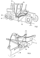
- FIG. 2 Another construction apparatus in the form of a trencher 40 includes a frame 42 and a trenching tool 44 (Fig. 2).
- a control assembly 46 is shown to include a fiber-optic bundle 48 extending from an electronic control module 50 positioned on frame 42 to a location on trencher tool 44. This allows trencher tool 44, which pivots with respect to frame 42, to be monitored in its angular orientation with respect to the frame.
- Trencher 40 may, otherwise, be of the type disclosed in commonly assigned United States Patent 5,559,725, the disclosure of which is hereby incorporated herein by reference.
- a control 58 includes a fiber-optic bundle 60 extending from blade 56 to a stationary platform 62.
- An electronic control module 64 monitors the position of blade 56 with respect to platform 62 about vertical axis V.
- Grader 52 additionally includes a bogie 66, which mounts drive wheels 68.
- Bogie 66 provides limited pivotal motion about a vertical axis (not shown) with respect to grader frame 54.
- bogie 66 pivots about its vertical axis in order to accommodate movement of the grader 52 as it traverses the surface to be graded.
- the bogie seeks an accommodating position. This may result in the grader "crabbing" when the bogie is not aligned with the front wheels of the grader.
- a control system could be used to monitor bogie 66 and provide information to a master control for grader 52 that would take into account the degree of crabbing of the bogie, the details of which would be understood by the skilled artisan.
Landscapes
- Engineering & Computer Science (AREA)
- Mechanical Engineering (AREA)
- Mining & Mineral Resources (AREA)
- Civil Engineering (AREA)
- General Engineering & Computer Science (AREA)
- Structural Engineering (AREA)
- Physics & Mathematics (AREA)
- General Physics & Mathematics (AREA)
- Operation Control Of Excavators (AREA)
- Component Parts Of Construction Machinery (AREA)
Applications Claiming Priority (2)
| Application Number | Priority Date | Filing Date | Title |
|---|---|---|---|
| US16426199P | 1999-11-09 | 1999-11-09 | |
| US164261P | 1999-11-09 |
Publications (2)
| Publication Number | Publication Date |
|---|---|
| EP1099802A2 true EP1099802A2 (de) | 2001-05-16 |
| EP1099802A3 EP1099802A3 (de) | 2002-01-30 |
Family
ID=22593699
Family Applications (1)
| Application Number | Title | Priority Date | Filing Date |
|---|---|---|---|
| EP00650188A Withdrawn EP1099802A3 (de) | 1999-11-09 | 2000-11-09 | Positions- und Orientierungsgeber für eine Baumaschine |
Country Status (1)
| Country | Link |
|---|---|
| EP (1) | EP1099802A3 (de) |
Cited By (4)
| Publication number | Priority date | Publication date | Assignee | Title |
|---|---|---|---|---|
| US7734398B2 (en) | 2006-07-31 | 2010-06-08 | Caterpillar Inc. | System for automated excavation contour control |
| CN103362173A (zh) * | 2013-07-31 | 2013-10-23 | 王均义 | 装载机铲斗触地感测装置 |
| US9975472B2 (en) | 2015-04-30 | 2018-05-22 | Tyri International, Inc. | Controllable lighting arrangement for a vehicle |
| AU2020202517B2 (en) * | 2013-11-25 | 2022-04-21 | Esco Group Llc | Wear part monitoring |
Family Cites Families (7)
| Publication number | Priority date | Publication date | Assignee | Title |
|---|---|---|---|---|
| US3735818A (en) * | 1969-01-23 | 1973-05-29 | Cmi Corp Oklahoma City | Motor-grader implements |
| GB1390066A (en) * | 1971-03-17 | 1975-04-09 | Grad Line | Grader control |
| US4888890A (en) * | 1988-11-14 | 1989-12-26 | Spectra-Physics, Inc. | Laser control of excavating machine digging depth |
| US5633494A (en) * | 1991-07-31 | 1997-05-27 | Danisch; Lee | Fiber optic bending and positioning sensor with selected curved light emission surfaces |
| US5249379A (en) * | 1992-09-15 | 1993-10-05 | Eagle-Picher Industries, Inc. | Mounting structure for the linear actuators of a trenching apparatus |
| JP2566745B2 (ja) * | 1994-04-29 | 1996-12-25 | 三星重工業株式会社 | 電子制御油圧掘削機の自動平坦作業方法 |
| JPH09144056A (ja) * | 1995-11-29 | 1997-06-03 | Sumitomo Constr Mach Co Ltd | トレンチャーの掘削位置検出装置 |
-
2000
- 2000-11-09 EP EP00650188A patent/EP1099802A3/de not_active Withdrawn
Cited By (5)
| Publication number | Priority date | Publication date | Assignee | Title |
|---|---|---|---|---|
| US7734398B2 (en) | 2006-07-31 | 2010-06-08 | Caterpillar Inc. | System for automated excavation contour control |
| CN103362173A (zh) * | 2013-07-31 | 2013-10-23 | 王均义 | 装载机铲斗触地感测装置 |
| CN103362173B (zh) * | 2013-07-31 | 2015-05-20 | 王均义 | 装载机铲斗触地感测装置 |
| AU2020202517B2 (en) * | 2013-11-25 | 2022-04-21 | Esco Group Llc | Wear part monitoring |
| US9975472B2 (en) | 2015-04-30 | 2018-05-22 | Tyri International, Inc. | Controllable lighting arrangement for a vehicle |
Also Published As
| Publication number | Publication date |
|---|---|
| EP1099802A3 (de) | 2002-01-30 |
Similar Documents
| Publication | Publication Date | Title |
|---|---|---|
| US7810260B2 (en) | Control system for tool coupling | |
| US8843279B2 (en) | Method and apparatus for determining a spatial positioning of loading equipment | |
| US4129224A (en) | Automatic control of backhoe digging depth | |
| US8082084B2 (en) | Loader and loader control system | |
| US8122974B2 (en) | Apparatus for drilling machine alignment | |
| US12134880B2 (en) | Position detection device and method for detecting the position of a bucket of an excavator | |
| US7293376B2 (en) | Grading control system | |
| JP6546558B2 (ja) | 建設機械及び建設機械の較正方法 | |
| US9803477B2 (en) | Fiber optic shape sensing adapted to cutter module of highwall miner | |
| US5559725A (en) | Automatic depth control for trencher | |
| JPH0633612B2 (ja) | 掘削装置を運転する方法および掘削装置 | |
| EP1099802A2 (de) | Positions- und Orientierungsgeber für eine Baumaschine | |
| US20060124323A1 (en) | Work linkage position determining system | |
| US20160097658A1 (en) | Fiber optic implement position determination system | |
| JP2001074413A (ja) | 反射表面への距離を測定する装置及び方法 | |
| US11248455B2 (en) | Acoustic geosteering in directional drilling | |
| US5550757A (en) | Method for determination of the position of an elongated piece | |
| JP2982890B2 (ja) | 地盤掘削機の姿勢計測装置および姿勢制御方法 | |
| US20150020605A1 (en) | System for locating electric cables | |
| KR20000024991A (ko) | 굴삭기의 버켓 변위 측정장치 및 그 측정방법 | |
| JP4208062B2 (ja) | 土構造物用すべり検知補強杭 | |
| KR20120131132A (ko) | 굴삭기의 레벨 측정장치 | |
| KR101243930B1 (ko) | 굴삭기의 레벨 측정장치 | |
| FI104584B (fi) | Menetelmä pitkänomaisen kappaleen aseman määrittämiseksi | |
| JP4256526B2 (ja) | 地中掘削機の変位計測装置 |
Legal Events
| Date | Code | Title | Description |
|---|---|---|---|
| PUAI | Public reference made under article 153(3) epc to a published international application that has entered the european phase |
Free format text: ORIGINAL CODE: 0009012 |
|
| AK | Designated contracting states |
Kind code of ref document: A2 Designated state(s): AT BE CH CY DE DK ES FI FR GB GR IE IT LI LU MC NL PT SE TR |
|
| AX | Request for extension of the european patent |
Free format text: AL;LT;LV;MK;RO;SI |
|
| PUAL | Search report despatched |
Free format text: ORIGINAL CODE: 0009013 |
|
| AK | Designated contracting states |
Kind code of ref document: A3 Designated state(s): AT BE CH CY DE DK ES FI FR GB GR IE IT LI LU MC NL PT SE TR |
|
| AX | Request for extension of the european patent |
Free format text: AL;LT;LV;MK;RO;SI |
|
| RIC1 | Information provided on ipc code assigned before grant |
Free format text: 7E 02F 9/20 A, 7E 02F 9/26 B, 7E 02F 3/84 B, 7G 01D 5/353 B |
|
| AKX | Designation fees paid | ||
| REG | Reference to a national code |
Ref country code: DE Ref legal event code: 8566 |
|
| STAA | Information on the status of an ep patent application or granted ep patent |
Free format text: STATUS: THE APPLICATION IS DEEMED TO BE WITHDRAWN |
|
| 18D | Application deemed to be withdrawn |
Effective date: 20020731 |