EP1099824A2 - Dispositif de préhension et relâchement au choix de tubes - Google Patents
Dispositif de préhension et relâchement au choix de tubes Download PDFInfo
- Publication number
- EP1099824A2 EP1099824A2 EP01200460A EP01200460A EP1099824A2 EP 1099824 A2 EP1099824 A2 EP 1099824A2 EP 01200460 A EP01200460 A EP 01200460A EP 01200460 A EP01200460 A EP 01200460A EP 1099824 A2 EP1099824 A2 EP 1099824A2
- Authority
- EP
- European Patent Office
- Prior art keywords
- spider
- elevator
- valve
- pressure
- slips
- Prior art date
- Legal status (The legal status is an assumption and is not a legal conclusion. Google has not performed a legal analysis and makes no representation as to the accuracy of the status listed.)
- Granted
Links
Images



Classifications
-
- E—FIXED CONSTRUCTIONS
- E21—EARTH OR ROCK DRILLING; MINING
- E21B—EARTH OR ROCK DRILLING; OBTAINING OIL, GAS, WATER, SOLUBLE OR MELTABLE MATERIALS OR A SLURRY OF MINERALS FROM WELLS
- E21B19/00—Handling rods, casings, tubes or the like outside the borehole, e.g. in the derrick; Apparatus for feeding the rods or cables
- E21B19/02—Rod or cable suspensions
- E21B19/06—Elevators, i.e. rod- or tube-gripping devices
- E21B19/07—Slip-type elevators
Definitions
- This invention relates generally to methods and apparatus for installing and removing well bore pipe, and more particularly pertains to a pressure interlock system with improved response time wherein the elevator slips are pneumatically actuated and the spider slips may be pneumatically or hydraulically actuated, and wherein the spider may be flush mounted.
- Pneumatic casing tools are gripping devices used to hold and lower tubes or tubular well casing into a pre-drilled hole.
- the tools are used in sets consisting of one elevator slip assembly and one spider slip assembly.
- the elevator and spider slip assemblies are functionally identical tools except for the accessories used to operate each tool.
- a problem associated with the use of these tools is related to gripping the casing collar which is of a larger diameter than the outside diameter of the well casing. The problem is caused when the elevator slip assembly is not lowered sufficiently below the collar.
- the slip assemblies are designed such that the gripping forces generated are sufficient for proper gripping only when the slips are lowered sufficiently below a casing collar so as to completely grip the outside diameter of the well casing and not the collar.
- the person working up in the derrick operates the control valves that close the elevator slips. Once the elevator slips are closed and the weight of the casing is on the elevator, the stabber sometimes actuates the control valve to the open direction. However, with the casing weight hanging on the elevator, the air pressure alone will not open the slips. The proper time to actuate the control valve is after the string is lowered and the spider assembly slips are closed, and not before.
- Another problem is that once an elevator or spider has been energized to the open or closed position, there is a time required to allow the tool to reach the gripped position, detect that this has occurred and have the interlock system respond accordingly. During this time the interlock system may not function properly.
- Flush mounted spiders utilize a series of hydraulic cylinders rather than pneumatic cylinders to power slips upward to the open position or downward to the closed position.
- Of particular danger, which is unique to the flush mounted spider is the ability of the spider slips to be opened inadvertently despite being engaged in the down position with casing suspended in the slips. This is possible due the substantial upward force which can be applied to the slips thus dislodging them from the closed position.
- the substantial force is the result of the high operating pressures that are typical of hydraulic systems 138 bar to 207 bar (2000 to 3000 psi) as opposed to the lower operating pressures 5.5 bar to 10.4 bar (80 to 150 psi) that are typical of pneumatically operated elevators and spiders. Additional problems arise due to the fact that the operational controls for this spider are located within a separate control panel as opposed to being mounted on the tool itself.
- Pneumatic conduits between the elevator and spider are typically about 36.5 m (120 feet) long and 19 mm (0.75 inches) in diameter.
- the fluid volumes from such conduits are large and the response to operation of control valves may be sluggish, possibly endangering the operator.
- the present invention includes pressure circuits where conduits that would have been 19 mm (0.75 inches) in diameter may be about 13 mm (0.5 inches) in diameter instead, and conduits that would have been 36.5 m (120 feet) long are now about 90 cm (3 feet) long.
- the smaller conduit lengths and diameters allowed by the present invention reduce the fluid volumes that must be handled by the apparatus. Smaller fluid volumes, in turn, result in improved response time and safer operation of the apparatus.
- An object of the present invention is an apparatus for gripping and releasing tubes so that one set of tube gripping slips is gripping the tube at all times and that one set of slips may not be released from the tube unless the other set of slips has a firm grip on the well casing.
- Another object of the present invention is to deactivate the elevator slips and/or the spider slips against inadvertent actuation unless the other set of slips are fully set in gripping position.
- Yet another object of the present invention is an apparatus having enhanced performance of the interlock system by improving the response time.
- a further object of the present invention is an apparatus for gripping an releasing a tube wherein at least one set of slips is actuated by hydraulic fluid pressure.
- an apparatus for controlling the gripping and releasing of a tubular member comprising an elevator with a set of slips for optionally gripping and releasing a tubular member; a spider with a set of slips for optionally gripping and releasing said tubular member; a pressure circuit in communication with said elevator slips and said spider slips to control the supply of pressure to release one set of slips only when the other set of slips is gripping said tubular member, wherein said pressure circuit comprising a plurality of interconnected elevator valves, spider valves, and conduit systems, and wherein at least one of said elevator valves and said spider valves is supplied by a pilot valve.
- the pressure circuit comprises elevator and spider pressure chambers for actuating the elevator or spider slips to grip or release the tube.
- the pressure circuit includes a plurality of interconnected elevator valves, spider valves, and conduit systems.
- the conduit systems comprise multi-position fluid pressure controlling valves to control or regulate the flow of pressure through the circuit and to actuate valves and slips into different positions.
- the apparatus may also include a drilling rig having a travelling block and a supportive rig floor, a casing gripping fluid actuated casing elevator assembly carried by the travelling block and a casing gripping fluid actuated casing spider assembly mounted on the rig floor.
- the elevator assembly and the spider assembly each has a piston in a pressurable closing chamber to actuate slips into gripping engagement with well casing when the closing chamber is pressurized, and also a pressurable opening chamber also containing a piston to move the slips into release from the casing when the opening chamber is pressurized.
- the opening and closing chambers may sometimes be referred to collectively herein as the elevator or spider pressure chamber.
- the spider may be controlled remotely from said spider.
- the spider may be a flush mounted spider.
- One set of slips may be actuated by hydraulic pressure and the other set of slips by pneumatic pressure.
- the communication and control circuitry of the apparatus may be electrical.
- the pressure circuit of the apparatus may include:
- the pressure circuit may also include an additional elevator valve and an additional spider valve each of which can be used to optionally open and close one set of slips regardless of the position of the other set of slips.
- These valves are manual bypass valves that are ordinarily are always in position to supply pressure through the circuit as the interlock valves direct, but may be manually actuated to switch to a direct pressure supply to override the usual operation of the interlock circuit.
- the elevator bypass valve may be connected between the second and third elevator valves, and the spider bypass valve may be connected between the second and third spider valves.
- the apparatus may also include a flush mounted spider assembly where the spider slips position is sensed directly.
- the apparatus with a flush mounted spider includes an elevator assembly substantially the same as previously described and a flush mounted spider with a spider control console connected remotely to said spider including:
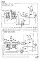
- the elevator slips are controlled pneumatically and the spider slips are actuated hydraulically and remotely from the spider assembly and the spider slip position is sensed in the spider hydraulics, the pressure circuit then includes:
- the preferred embodiment also includes an additional spider valve and an additional elevator valve connected to said pressure circuit to optionally open and close one set of slips regardless of the position of the other set of slips.
- VALVE DESCRIPTIONS 58-4-way two position pneumatic directional control valve manual lever Used to raise and lower slips, only functions if valve #72 has pilot signal 158-4-way two position pneumatic directional control valve, manual lever Used to raise and lower slips, only functions if valve #72 has pilot signal 72-3-way two position pneumatic directional control valve, spring offset, pilot operated Blocks air supply to valve #58 until slips are set on spider, valve #60 actuated 160-3-way two position pneumatic directional control valve, spring offset, cam operated Sends pilot signal to valve #78 when valve #76 is in the interlock position 74-3-way manual ball valve Selects air source, either air supply or pilot from valve #84 88-3-way two position hydraulic directional control valve, spring offset, hydraulic pilot Sends pilot oil to pilot on valve #84, sending air signal to valve #74 and valve #72 if valve #74 is in interlock position.
- valve #80 & #82 are shifted to both up or both down position 82-5-way pneumatic directional control valve, two position, detent Used in conjunction with valve #80 to raise and lower slips 80-5-way pneumatic directional control valve, two position, detent Used in conjunction with valve #82 to raise and lower slips 78-3-way two position pneumatic directional control valve, spring offset, pneumatic pilot Blocks air supply to valves #82 & #80 until slips are set on elevator, valve #160 actuated and valve #76 in the interlock position 76-3-way manual ball valve Selects air source, either air supply or pilot from valve #160 90-hydraulic selector valve, dual pressure Reduces available pressure to set slips until valve #60 is actuated 60-4-way two position hydraulic directional control valve, cam operated Selects high pressure when slip
- FIG. 1 there is shown the pertinent portion of a drilling rig 10 which is rigged to run well casing with an elevator slip assembly 12 suspended from links 28 and a travelling block 26 (indicated in dashed lines), and a spider slip assembly 18 supported on the rig casing guide 16.
- the spider assembly 18 carries a bottom guide 20, shown in dashed lines, and a spider top guide 22 as shown.
- the elevator and the spider are air actuated from an air supply 42 which passes through a conduit or hose 38 to the elevator 12 and through a conduit or hose 40 to the spider 18.
- an air supply 42 which passes through a conduit or hose 38 to the elevator 12 and through a conduit or hose 40 to the spider 18.
- conduits or hoses 44A and 46A Interconnected between the elevator 12 and the spider 18 are conduits or hoses 44A and 46A which have a purpose made more clear with reference to FIG. 4.
- FIG. 2 schematically illustrates a slip member 30 seated in a slip bowl 32 and firmly engaged in gripping contact with well casing 34 just below a casing collar 36.
- This FIG. 2 illustrates the internal configuration of both the elevator 12 and the spider 18 when the slips 30 are correctly seated.
- FIG. 3 schematically illustrates a situation where the slip member 30 has engaged with the casing collar 36, has not been correctly seated in the slip bowl 32, and has not been seated correctly around the casing 34.
- the "cocking" of the slip 30 is exaggerated but it can be seen that the gripping action of slip member 30 is precarious at best and subject to being dislodged with little “bumping" of the casing against some obstruction in the well bore.
- the elevator slip assembly 12 and the slip spider assembly 18 are illustrated in FIG. 4 purely for functionality and do not reflect the actual internal construction of the elevator 12 and the spider 18 as appearing in FIG. 1. It will be seen that the schematic representation of elevator 12 and spider 18 is similar to corresponding assemblies as shown in U.S.-A-4,676,312. Though schematic and functional, the elevator 12 and the spider 18 as shown in FIG. 4 accurately correspond to the function of the same elements or parts thereof as shown in FIGS. 1-3.
- the elevator 12 is to include a plurality of slips 30 adapted to be guided into a slip bowl 32 to be engaged and disengaged from the well casing 34.
- the slips 30 are pulled up in retracted position so as to be free and clear of the casing 34 and the casing collar 36.
- the elevator 12 is equipped with two slip piston cylinder assemblies 48 which form respectively a slip release pressure chamber 50 and a slip closure pressure chamber 52.
- the slip release chambers 50 are connected through a conduit 54 into a manually actuated two-position slip actuator valve 58.
- the slip closure chambers 52 are connected through a slip closure conduit or line 56 also into the two-position valve 58.
- the valve 58 is adapted to admit fluid pressure into slip release chambers 50 while venting fluid pressure from the slip closure chambers 52 through the line 56 to atmosphere. When the valve 58 is shifted to its second position, fluid pressure is admitted to the slip closure chambers 52 while venting pressure from the release chambers 50 through line 54 to atmosphere.
- Valve #58 is supplied with air through line 502 via valve #72 which is piloted by valve #60 which is physically mounted on the spider.
- Valve #60 is actuated by the slip lowering/opening mechanism on the spider. Once the spider slips are properly set, or valve #60 is mechanically actuated so as to send a signal to valve #72 opening valve #72 thus permitting flow of air to valve #58 and onward to the rod end of the pneumatic cylinders on the elevator slip close mechanism forcing the slips downward into engagement with the pipe.
- valve #158 Once elevator is set, release slips on spider by manually shifting valve #158 on standard air spider to the up position. Valve #158 will have an air source if valve #160 on the elevator has been actuated by the elevator slip close mechanism signalling that the elevator slips have been properly set on the pipe body. The signal from valve #160 pilots valve #78 so as to allow air flow through line #501 to valve #158. If the elevator is not set properly on the pipe, valve #160 will not be shifted and no pilot air will be available to valve #78 making it not possible to open the slips on the spider.
- the string is lowered through the spider until the elevator is just above the spider.
- the spider slips are set as described in Step 1 and the next joint is lifted into position for make up. Should someone shift the spider valve #158 on the spider before the elevator is in position and slips have been properly set, the spider will not open because valve #160 on the elevator has not been actuated signalling that the elevator slip have been properly set. This would prevent the string of pipe from being dropped down hole.
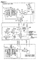
- fluid pressure is admitted into the control valve 58 through a conduit or line 502 from a two-position, spring offset pilot valve 72 which is actuated into position to admit fluid pressure to control valve 58 by fluid pressure admitted through a three-way elevator interlock valve 74 connected to optionally admit fluid pressure either from a direct supply such as compressed air (FIG. 6) through line 46A, or from two-position spider control console valve 84 (FIG. 7) through line 46A.
- Line 502 may be as short as approximately 90 cm (3 feet) in length and as narrow as approximately 12.5 mm (0.5 inches) in diameter, as compared to 19 mm (0.75 inches) in diameter for typical elevator conduits.
- Line 44A may be about 36.5 m (120 feet) in length, but only approximately 6 mm (0.25 inches) in diameter as compared to 19 mm (0.75 inches) as is typical for elevator-spider conduits.
- Pilot valve 84 is actuated to admit fluid pressure to elevator interlock valve 74 by fluid pressure admitted through a two-position, spring offset, pilot valve 88 which is actuated in turn by fluid pressure passing through pressure selector valve 90.
- Pressure selector valve 90 admits fluid pressure to spider closing chamber 152 to close the spider, and is actuated by fluid pressure admitted through control valve 60 into position to supply reduced hydraulic pressure to spider slips 30 when the spider 18 is fully closed into gripping position (FIG. 6).
- Valve 90 is a safety feature of the apparatus.
- valve 90 is useful to moderate the force of the hydraulic pressure on the spider slips.
- Pilot valve 78 admits fluid pressure from a direct pneumatic fluid pressure source through line or conduit 501 to a manually operated, two-position control console valves 80 and 82 only when the elevator 160 is fully closed into gripping position.
- Line 501 may be as short as approximately 90 cm (3 feet) in length and as narrow as approximately 12.5 mm (0.5 inches) in diameter.
- Control console valves 80 and 82 must both be in position to admit fluid pressure to actuate two-position, spring offset pilot valve 86 to admit fluid pressure from a hydraulic source to open and close the spider 18.
- Pilot valve 78 is actuated through interlock valve 76, only when the elevator 12 is closed, by fluid pressure admitted when elevator slip position sensing valve 160 is actuated into position to admit fluid pressure by the elevator 12 being fully closed into gripping position.
- Position sensing valve 160 is a two-position, spring offset valve mechanically actuated into position to admit fluid pressure to interlock valve 76 only when the elevator is fully closed into gripping position. If the elevator is in any position other than fully closed into gripping position, valve 160 blocks fluid pressure supply to valve 76 from a direct pneumatic source and vents to atmosphere fluid pressure from the elevator closing chamber 52. Pilot valves 72 and 78 allow for conduits of overall small fluid volume in the apparatus and improved response time.
- the elevator being used is a conventional air operated type elevator and the spider is a Flush Mount Type Spider powered by hydraulics.
- the spider hydraulic control valves are located within a separate control console.
- the spider interlock function is accomplished by the use of a pneumatic slip position sensing valve which is mounted in the spider apparatus itself (The procedure described below is the same irrespective of whether casing or tubing is being run, therefore for simplicity we will refer to casing when referring to the pipe being run but this is not intended to limit the scope of this procedure to casing applications.)
- Valve #58 is supplied with air through line 502 via valve #72 which is piloted by valve #60 which is physically mounted on the spider.
- Valve #60 is actuated by the slip lowering/opening mechanism on the spider. Once the spider slips are properly set, or valve #60 is mechanically actuated so as to send a signal to valve #72 opening valve #72 thus permitting flow of air to valve #58 an onward to the rod end of the pneumatic cylinders on the elevator slip close mechanism forcing the slips downward into engagement with the pipe.
- valve #'s 80 and 82 are supplied with air via valve #78 and valve #78 is piloted to supply air if valve #160 on the elevator has been actuated by the elevator slip close mechanism signalling that the elevator slips have been properly set on the pipe body. If the elevator is not set properly on the pipe, valve #160 will not be shifted and no pilot air will be available to valve #78 making it not possible to open the slips on the spider.
- FIGS. 4, 6, 7, and 8 in view of FIGS. 1 and 2, the spider 18 is set on the rig floor and the elevator 12 is suspended from the travelling block 26 and links 28 as shown.
- the casing string 34 is suspended into the hole from elevator 12 and lowered by the travelling block 26.
- the slips in the spider 18 are opened and the pipe 34 travels freely through it.
- the slips of the elevator are closed and firmly grip casing 34.
- the elevator 12 is lowered over the casing to a point below the collar at the top of that last joint.
- the elevator slips 30 are then closed by actuating elevator control 58 to supply pneumatic pressure to elevator closing chamber 52 and the elevator is used to lift the casing 34 a very short distance. This short lift is to enable the slips 130 and the spider 18 to be opened.
- the casing string 34 is again suspended from the elevator 12, thus allowing the whole string to be lowered to start the sequence again for another single joint of casing.
- the gripping system shown in FIGS. 4 through 8 assures that, at all times, one set of the slips 30 or 130 are closed into firm gripping contact with the body of the casing 34. If one set is not closed then the other set will not be able to be energized to be released.
- the piloted valve 72 and 78 shown in FIGS. 4 through 8 reduces the volume of compressed fluid that must be released to the atmosphere each time the elevator or spider is operated resulting in improved response time of the gripping assembly.
- Spider control console valve 86 is actuated by pneumatic pressure supplied from valve 82 to supply hydraulic pressure from a hydraulic pressure supply to open and close the spider slips 130.
- Spider valve 88 is actuated by the hydraulic pressure supplied through valve 86 to supply hydraulic pressure to actuate spider control valve 84 to supply pneumatic pressure to elevator pilot valve 72.
- interlock valve 60 and 160 positioning of the interlock valve 60 and 160 by their respective linkages 70 and 170 is critical such that the respective actuating valves 58 and 158 may be actuated only when the other of the respective slips 30 and 130 are closed into firm gripping engagement with the pipe body. Closing either set of slips on a larger diameter such as a collar 36 would not permit the respective position valve 60 or 160 to actuate as described. The system therefore assures that at least one of elevator 12 or spider 18 will be firmly gripping the casing 34 at all times.
- the elevator being used is a conventional air operated type elevator and the spider is a Flush Mount Type Spider powered by hydraulics.
- the spider hydraulic control valves are located within a separate control console.
- the spider interlock function is accomplished by the use of a hydraulic slip position sensing valve #60 which is mounted in the spider apparatus itself
- the hydraulic slip position sensing valve regulates the hydraulic cylinder pressure (via control of valve #90 being applied to the rod ends of the spider slip set cylinders.
- Slip position sensing valve #60 restricts the pressure being applied to the cylinders to a low level of approximately 34.5 bar (500 psi) until the spider slips are properly set at which time valve #60 is actuated and the pressure being applied to the cylinders is increased to approximately 138 bar (2000 psi).
- Valve #88 located in the spider control console monitors this varying pressure and is actuated at 69 bar (1000 psi) to send a signal to valve #84 also located in the console.
- valve #60 is actuated and the hydraulic pressure rises from the 34.5 bar (500 psi) set point to 138 bar (2000 psi) resulting in valve #88 being actuated sending a signal to actuate valve #84.
- Actuation of valve #84 sends a signal via line 44A to valve #72 located on the elevator which in turn supplies air pressure to the inlet of manual valve #58 making it possible to open the elevator slips.
- Valve #58 is supplied with air through line 502 via valve #72 which is piloted by valve #84 which is piloted by valve #88.
- Valve 88 responds to the changing hydraulic pressure when the spider slips are properly set.
- valve #60 is mechanically actuated increasing the hydraulic system pressure from 34.5 bar (500 psi) to 138 bar (2000 psi) and in accordance with the circuit description above results in valve #72 on the elevator being actuated thus permitting flow of air to valve #58 and onward to the rod end of the pneumatic cylinders on the elevator slip close mechanism forcing the slips downward into engagement with the pipe.
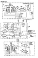
- the control valves are now illustrated in FIG. 8.
- valves #80 and #82 on the spider control console release the spider slips by manually shifting valves #80 and #82 on the spider control console to the up position.
- Valves #'s 80 and 82 are supplied with air via valve #78 and valve #78 is piloted to supply air if valve #160 on the elevator has been actuated by the elevator slip close mechanism signalling that the elevator slips have been properly set on the pipe body. If the elevator is not set properly on the pipe, valve #160 will not be shifted and no pilot air will be available to valve #78 making it not possible to open the slips on the spider.
- the control valves are now illustrated in FIG. 7.
- Line 44A may be approximately 36.5 bar (120 feet) in length, but only 6 mm (0.25 inches) in diameter, as compared with 19 mm (0.75 inches) diameters typically used for elevator-spider conduits.
- the system described above is one that utilized compressed air to open and close the slips as well as a way of transmitting signals from one tool to the other. It is readily seen that the same interlock system herein described could be used in a hydraulic circuit equally well, providing that various components are designed for hydraulic operation.
- An hydraulically operated Flush Mount Spider may be utilized with a pneumatically operated elevator and as shown in FIGS. 5, 6, and 7, a control console 270 may be connected remotely to the flush mounted spider 18.
- the system as herein described could be an electropneumatic system or an electrohydraulic system with the valves disclosed actuated by electrical solenoids connected through appropriate limits switches.
Landscapes
- Engineering & Computer Science (AREA)
- Geology (AREA)
- Mining & Mineral Resources (AREA)
- Life Sciences & Earth Sciences (AREA)
- General Life Sciences & Earth Sciences (AREA)
- Fluid Mechanics (AREA)
- Mechanical Engineering (AREA)
- Environmental & Geological Engineering (AREA)
- Physics & Mathematics (AREA)
- Geochemistry & Mineralogy (AREA)
- Types And Forms Of Lifts (AREA)
- Fluid-Pressure Circuits (AREA)
- Shaping Of Tube Ends By Bending Or Straightening (AREA)
- Lining Or Joining Of Plastics Or The Like (AREA)
- Manipulator (AREA)
Applications Claiming Priority (3)
| Application Number | Priority Date | Filing Date | Title |
|---|---|---|---|
| US08/783,933 US5791410A (en) | 1997-01-17 | 1997-01-17 | Apparatus and method for improved tubular grip assurance |
| US783933 | 1997-01-17 | ||
| EP97921333A EP0966592B1 (fr) | 1997-01-17 | 1997-04-21 | Dispositif et procede de serrage a surete amelioree d'un element tubulaire |
Related Parent Applications (1)
| Application Number | Title | Priority Date | Filing Date |
|---|---|---|---|
| EP97921333A Division EP0966592B1 (fr) | 1997-01-17 | 1997-04-21 | Dispositif et procede de serrage a surete amelioree d'un element tubulaire |
Publications (3)
| Publication Number | Publication Date |
|---|---|
| EP1099824A2 true EP1099824A2 (fr) | 2001-05-16 |
| EP1099824A3 EP1099824A3 (fr) | 2001-09-05 |
| EP1099824B1 EP1099824B1 (fr) | 2003-09-03 |
Family
ID=25130865
Family Applications (2)
| Application Number | Title | Priority Date | Filing Date |
|---|---|---|---|
| EP01200460A Expired - Lifetime EP1099824B1 (fr) | 1997-01-17 | 1997-04-21 | Dispositif de préhension et relâchement au choix de tubes |
| EP97921333A Expired - Lifetime EP0966592B1 (fr) | 1997-01-17 | 1997-04-21 | Dispositif et procede de serrage a surete amelioree d'un element tubulaire |
Family Applications After (1)
| Application Number | Title | Priority Date | Filing Date |
|---|---|---|---|
| EP97921333A Expired - Lifetime EP0966592B1 (fr) | 1997-01-17 | 1997-04-21 | Dispositif et procede de serrage a surete amelioree d'un element tubulaire |
Country Status (8)
| Country | Link |
|---|---|
| US (2) | US5791410A (fr) |
| EP (2) | EP1099824B1 (fr) |
| AU (1) | AU2739697A (fr) |
| CA (1) | CA2274650C (fr) |
| DE (2) | DE69724670T2 (fr) |
| DK (2) | DK1099824T3 (fr) |
| NO (1) | NO313967B1 (fr) |
| WO (1) | WO1998031914A1 (fr) |
Cited By (2)
| Publication number | Priority date | Publication date | Assignee | Title |
|---|---|---|---|---|
| WO2004101417A3 (fr) * | 2003-05-15 | 2005-02-03 | Matheus Christensen | Elevateur se deplaçant a l'interieur |
| US7086461B2 (en) | 2000-11-04 | 2006-08-08 | Weatherford/Lamb, Inc. | Combined grip control of elevator and spider slips |
Families Citing this family (121)
| Publication number | Priority date | Publication date | Assignee | Title |
|---|---|---|---|---|
| US7036610B1 (en) | 1994-10-14 | 2006-05-02 | Weatherford / Lamb, Inc. | Apparatus and method for completing oil and gas wells |
| US7108084B2 (en) | 1994-10-14 | 2006-09-19 | Weatherford/Lamb, Inc. | Methods and apparatus for cementing drill strings in place for one pass drilling and completion of oil and gas wells |
| US7147068B2 (en) | 1994-10-14 | 2006-12-12 | Weatherford / Lamb, Inc. | Methods and apparatus for cementing drill strings in place for one pass drilling and completion of oil and gas wells |
| US7228901B2 (en) | 1994-10-14 | 2007-06-12 | Weatherford/Lamb, Inc. | Method and apparatus for cementing drill strings in place for one pass drilling and completion of oil and gas wells |
| US7040420B2 (en) | 1994-10-14 | 2006-05-09 | Weatherford/Lamb, Inc. | Methods and apparatus for cementing drill strings in place for one pass drilling and completion of oil and gas wells |
| US7013997B2 (en) | 1994-10-14 | 2006-03-21 | Weatherford/Lamb, Inc. | Methods and apparatus for cementing drill strings in place for one pass drilling and completion of oil and gas wells |
| US7100710B2 (en) | 1994-10-14 | 2006-09-05 | Weatherford/Lamb, Inc. | Methods and apparatus for cementing drill strings in place for one pass drilling and completion of oil and gas wells |
| US6868906B1 (en) | 1994-10-14 | 2005-03-22 | Weatherford/Lamb, Inc. | Closed-loop conveyance systems for well servicing |
| US6056060A (en) * | 1996-08-23 | 2000-05-02 | Weatherford/Lamb, Inc. | Compensator system for wellbore tubulars |
| US5850877A (en) * | 1996-08-23 | 1998-12-22 | Weatherford/Lamb, Inc. | Joint compensator |
| US5791410A (en) * | 1997-01-17 | 1998-08-11 | Frank's Casing Crew & Rental Tools, Inc. | Apparatus and method for improved tubular grip assurance |
| EP0887510B1 (fr) * | 1997-06-25 | 2003-10-01 | Weatherford/Lamb, Inc. | Système de commutation de sécurité pour élévateurs du type à coin de retenue |
| US6536520B1 (en) | 2000-04-17 | 2003-03-25 | Weatherford/Lamb, Inc. | Top drive casing system |
| US7140445B2 (en) | 1997-09-02 | 2006-11-28 | Weatherford/Lamb, Inc. | Method and apparatus for drilling with casing |
| US7509722B2 (en) | 1997-09-02 | 2009-03-31 | Weatherford/Lamb, Inc. | Positioning and spinning device |
| US6742596B2 (en) | 2001-05-17 | 2004-06-01 | Weatherford/Lamb, Inc. | Apparatus and methods for tubular makeup interlock |
| DE19747468C1 (de) * | 1997-10-28 | 1999-04-01 | Weatherford Oil Tool | Klemmvorrichtung zum Halten von Rohren |
| ATE220758T1 (de) * | 1997-12-24 | 2002-08-15 | Well Engineering Partners B V | Herstellen und aufbrechen von verbindungen zwischen bohrrohrsträngen |
| US6079490A (en) * | 1998-04-10 | 2000-06-27 | Newman; Frederic M. | Remotely accessible mobile repair unit for wells |
| GB9815809D0 (en) * | 1998-07-22 | 1998-09-16 | Appleton Robert P | Casing running tool |
| GB2340857A (en) | 1998-08-24 | 2000-03-01 | Weatherford Lamb | An apparatus for facilitating the connection of tubulars and alignment with a top drive |
| GB2340858A (en) | 1998-08-24 | 2000-03-01 | Weatherford Lamb | Methods and apparatus for facilitating the connection of tubulars using a top drive |
| GB2340859A (en) | 1998-08-24 | 2000-03-01 | Weatherford Lamb | Method and apparatus for facilitating the connection of tubulars using a top drive |
| US7188687B2 (en) | 1998-12-22 | 2007-03-13 | Weatherford/Lamb, Inc. | Downhole filter |
| WO2000037766A2 (fr) | 1998-12-22 | 2000-06-29 | Weatherford/Lamb, Inc. | Procedes et materiel de façonnage et d'assemblage de tuyaux |
| GB2345074A (en) | 1998-12-24 | 2000-06-28 | Weatherford Lamb | Floating joint to facilitate the connection of tubulars using a top drive |
| GB2347441B (en) | 1998-12-24 | 2003-03-05 | Weatherford Lamb | Apparatus and method for facilitating the connection of tubulars using a top drive |
| US6857487B2 (en) | 2002-12-30 | 2005-02-22 | Weatherford/Lamb, Inc. | Drilling with concentric strings of casing |
| US7311148B2 (en) | 1999-02-25 | 2007-12-25 | Weatherford/Lamb, Inc. | Methods and apparatus for wellbore construction and completion |
| US6896075B2 (en) | 2002-10-11 | 2005-05-24 | Weatherford/Lamb, Inc. | Apparatus and methods for drilling with casing |
| US6394201B1 (en) | 1999-10-04 | 2002-05-28 | Universe Machine Corporation | Tubing spider |
| US7216727B2 (en) | 1999-12-22 | 2007-05-15 | Weatherford/Lamb, Inc. | Drilling bit for drilling while running casing |
| US7334650B2 (en) | 2000-04-13 | 2008-02-26 | Weatherford/Lamb, Inc. | Apparatus and methods for drilling a wellbore using casing |
| US7325610B2 (en) | 2000-04-17 | 2008-02-05 | Weatherford/Lamb, Inc. | Methods and apparatus for handling and drilling with tubulars or casing |
| GB0010378D0 (en) | 2000-04-28 | 2000-06-14 | Bbl Downhole Tools Ltd | Expandable apparatus for drift and reaming a borehole |
| GB2365463B (en) | 2000-08-01 | 2005-02-16 | Renovus Ltd | Drilling method |
| GB2357530B (en) * | 2000-11-04 | 2003-09-03 | Weatherford Lamb | Method and apparatus for gripping tubulars |
| GB0101259D0 (en) | 2001-01-18 | 2001-02-28 | Wellserv Plc | Apparatus and method |
| US6557641B2 (en) * | 2001-05-10 | 2003-05-06 | Frank's Casing Crew & Rental Tools, Inc. | Modular wellbore tubular handling system and method |
| AU2013200093B2 (en) * | 2001-05-17 | 2016-08-11 | Weatherford Technology Holdings, Llc | Apparatus and methods for tubular makeup interlock |
| US6626238B2 (en) | 2001-12-12 | 2003-09-30 | Offshore Energy Services, Inc. | Remote sensor for determining proper placement of elevator slips |
| US6615931B2 (en) | 2002-01-07 | 2003-09-09 | Boart Longyear Co. | Continuous feed drilling system |
| GB0206227D0 (en) | 2002-03-16 | 2002-05-01 | Weatherford Lamb | Bore-lining and drilling |
| US6994176B2 (en) | 2002-07-29 | 2006-02-07 | Weatherford/Lamb, Inc. | Adjustable rotating guides for spider or elevator |
| US6899186B2 (en) | 2002-12-13 | 2005-05-31 | Weatherford/Lamb, Inc. | Apparatus and method of drilling with casing |
| US7303022B2 (en) | 2002-10-11 | 2007-12-04 | Weatherford/Lamb, Inc. | Wired casing |
| US7222677B2 (en) * | 2002-12-10 | 2007-05-29 | Frank's Casing Crew & Rental Tools, Inc. | Control line guide and method of using same |
| US7128154B2 (en) | 2003-01-30 | 2006-10-31 | Weatherford/Lamb, Inc. | Single-direction cementing plug |
| USRE42877E1 (en) | 2003-02-07 | 2011-11-01 | Weatherford/Lamb, Inc. | Methods and apparatus for wellbore construction and completion |
| WO2004076804A1 (fr) | 2003-02-27 | 2004-09-10 | Weatherford/Lamb Inc. | Sabot de forage |
| CA2517895C (fr) | 2003-03-05 | 2009-12-01 | Weatherford/Lamb, Inc. | Systeme d'exploitation et de forage avec cuvelage |
| US7874352B2 (en) | 2003-03-05 | 2011-01-25 | Weatherford/Lamb, Inc. | Apparatus for gripping a tubular on a drilling rig |
| US7503397B2 (en) | 2004-07-30 | 2009-03-17 | Weatherford/Lamb, Inc. | Apparatus and methods of setting and retrieving casing with drilling latch and bottom hole assembly |
| US7360594B2 (en) | 2003-03-05 | 2008-04-22 | Weatherford/Lamb, Inc. | Drilling with casing latch |
| CA2517883C (fr) | 2003-03-05 | 2010-01-12 | Weatherford/Lamb, Inc. | Puits de forage tubes a passage integral |
| WO2004090279A1 (fr) | 2003-04-04 | 2004-10-21 | Weatherford/Lamb, Inc. | Procede et appareil de manipulation de materiel tubulaire pour puits de forage |
| US7650944B1 (en) | 2003-07-11 | 2010-01-26 | Weatherford/Lamb, Inc. | Vessel for well intervention |
| US6968895B2 (en) * | 2003-09-09 | 2005-11-29 | Frank's Casing Crew And Rental Tools | Drilling rig elevator safety system |
| US7264067B2 (en) | 2003-10-03 | 2007-09-04 | Weatherford/Lamb, Inc. | Method of drilling and completing multiple wellbores inside a single caisson |
| US7284617B2 (en) | 2004-05-20 | 2007-10-23 | Weatherford/Lamb, Inc. | Casing running head |
| US8051909B2 (en) * | 2004-07-16 | 2011-11-08 | Frank's Casing Crew & Rental Tools, Inc. | Method and apparatus for positioning the proximal end of a tubular string above a spider |
| DE602005006198T2 (de) | 2004-07-20 | 2009-07-09 | Weatherford/Lamb, Inc., Houston | Oberantrieb zur Verbindung von Futterrohren |
| CA2532907C (fr) | 2005-01-12 | 2008-08-12 | Weatherford/Lamb, Inc. | Outil de remplissage et de circulation a une position |
| CA2533115C (fr) | 2005-01-18 | 2010-06-08 | Weatherford/Lamb, Inc. | Suramplificateur de couple d'entrainement par le haut |
| US7216717B2 (en) * | 2005-02-25 | 2007-05-15 | Blohm + Voss Repair Gmbh | Dual elevator system and method |
| US7296630B2 (en) * | 2005-02-25 | 2007-11-20 | Blohm + Voss Repair Gmbh | Hands-free bail-elevator locking device with combined power/control connector, bail spreader and method for use |
| CA2500253E (fr) * | 2005-03-10 | 2010-02-16 | Vernon Robert Boscher | Boitier de commande et de limitation des gaz pour foreuses sous pression en conjonction avec installation et entretien des forages |
| US7303021B2 (en) | 2005-09-20 | 2007-12-04 | Varco I/P, Inc. | Wellbore rig elevator systems |
| EP1963612B1 (fr) * | 2005-12-12 | 2010-04-14 | Weatherford/Lamb, Inc. | Dispositif de prehension de tubulaire sur un appareil de forage |
| EP2085568B1 (fr) | 2006-01-11 | 2011-08-31 | Weatherford/Lamb, Inc. | Support de compensateur |
| CA2586317C (fr) | 2006-04-27 | 2012-04-03 | Weatherford/Lamb, Inc. | Raccord de couple pour mecanisme d'entrainement superieur |
| DE102006038763A1 (de) * | 2006-08-17 | 2008-03-20 | Blohm + Voss Repair Gmbh | Vorrichtung zur Halterung von Bohrrohren |
| US7882902B2 (en) | 2006-11-17 | 2011-02-08 | Weatherford/Lamb, Inc. | Top drive interlock |
| US8141923B2 (en) * | 2007-01-19 | 2012-03-27 | Frank's Casing Crew And Rental Tools, Inc. | Single joint elevator having deployable jaws |
| WO2008134581A2 (fr) | 2007-04-27 | 2008-11-06 | Weatherford/Lamb, Inc. | Appareils et procédés pour verrouiller les connexions de conduites |
| US8240391B2 (en) * | 2007-05-09 | 2012-08-14 | Frank's Casing Crew And Rental Tools, Inc. | Single joint elevator with gripping jaws and method of hoisting a tubular member |
| US7992909B2 (en) * | 2007-07-12 | 2011-08-09 | Frank's Casing Crew And Rental Tools, Inc. | Single joint elevator with jaws secured by a powered door |
| DK2450524T3 (en) | 2007-12-12 | 2015-09-28 | Weatherford Technology Holdings Llc | Upper drive |
| WO2009137414A1 (fr) * | 2008-05-03 | 2009-11-12 | Frank's International, Inc. | Système de verrouillage de préhension tubulaire |
| CA2741532C (fr) | 2008-10-22 | 2014-01-28 | Frank's International, Inc. | Outil de pose de tubes a prise externe |
| US8439121B2 (en) * | 2009-11-16 | 2013-05-14 | Tesco Corporation | Hydraulic interlock system between casing gripper and spider |
| US8733454B2 (en) | 2010-03-01 | 2014-05-27 | Frank's Casing Crew And Rental Tools, Inc. | Elevator grip assurance |
| US9181763B2 (en) | 2010-03-24 | 2015-11-10 | 2M TEK, Inc. | Apparatus for supporting or handling tubulars |
| EP3176362B1 (fr) | 2010-12-17 | 2018-10-31 | Weatherford Technology Holdings, LLC | Système de commande électronique pour un outil de manipulation de matériel tubulaire |
| US9080398B2 (en) | 2010-12-23 | 2015-07-14 | Frank's International, Llc | Wellbore tubular running devices, systems and methods |
| WO2012100019A1 (fr) | 2011-01-21 | 2012-07-26 | 2M-Tek, Inc. | Dispositif et procédé pour descendre des tubulaires |
| CA2739280A1 (fr) * | 2011-05-05 | 2012-11-05 | Snubco Manufacturing Inc. | Systeme et methode de surveillance et de controle des foreuses sous pression |
| US9010443B2 (en) * | 2011-11-30 | 2015-04-21 | Halliburton Energy Services, Inc. | Slip bowl load transfer system |
| US9546525B2 (en) | 2013-10-18 | 2017-01-17 | Frank's International, Llc | Apparatus and methods for setting slips on a tubular member |
| WO2015061350A1 (fr) | 2013-10-21 | 2015-04-30 | Frank's International, Llc | Système de clé électrique et procédés d'utilisation |
| CN103615203A (zh) * | 2013-11-04 | 2014-03-05 | 中国石油集团渤海钻探工程有限公司 | 气动卡盘远程控制装置 |
| US9903167B2 (en) * | 2014-05-02 | 2018-02-27 | Tesco Corporation | Interlock system and method for drilling rig |
| US10626683B2 (en) | 2015-08-11 | 2020-04-21 | Weatherford Technology Holdings, Llc | Tool identification |
| US10465457B2 (en) | 2015-08-11 | 2019-11-05 | Weatherford Technology Holdings, Llc | Tool detection and alignment for tool installation |
| AU2016309001B2 (en) | 2015-08-20 | 2021-11-11 | Weatherford Technology Holdings, Llc | Top drive torque measurement device |
| US10323484B2 (en) | 2015-09-04 | 2019-06-18 | Weatherford Technology Holdings, Llc | Combined multi-coupler for a top drive and a method for using the same for constructing a wellbore |
| WO2017044482A1 (fr) | 2015-09-08 | 2017-03-16 | Weatherford Technology Holdings, Llc | Groupe électrogène pour unité d'entraînement supérieure |
| US10590744B2 (en) | 2015-09-10 | 2020-03-17 | Weatherford Technology Holdings, Llc | Modular connection system for top drive |
| US10167671B2 (en) | 2016-01-22 | 2019-01-01 | Weatherford Technology Holdings, Llc | Power supply for a top drive |
| US11162309B2 (en) | 2016-01-25 | 2021-11-02 | Weatherford Technology Holdings, Llc | Compensated top drive unit and elevator links |
| GB2550849B (en) * | 2016-05-23 | 2020-06-17 | Equinor Energy As | Interface and integration method for external control of the drilling control system |
| US10704364B2 (en) | 2017-02-27 | 2020-07-07 | Weatherford Technology Holdings, Llc | Coupler with threaded connection for pipe handler |
| US10954753B2 (en) | 2017-02-28 | 2021-03-23 | Weatherford Technology Holdings, Llc | Tool coupler with rotating coupling method for top drive |
| US11131151B2 (en) | 2017-03-02 | 2021-09-28 | Weatherford Technology Holdings, Llc | Tool coupler with sliding coupling members for top drive |
| US10480247B2 (en) | 2017-03-02 | 2019-11-19 | Weatherford Technology Holdings, Llc | Combined multi-coupler with rotating fixations for top drive |
| US10443326B2 (en) | 2017-03-09 | 2019-10-15 | Weatherford Technology Holdings, Llc | Combined multi-coupler |
| US10247246B2 (en) | 2017-03-13 | 2019-04-02 | Weatherford Technology Holdings, Llc | Tool coupler with threaded connection for top drive |
| US10801275B2 (en) * | 2017-05-25 | 2020-10-13 | Forum Us, Inc. | Elevator system for supporting a tubular member |
| US10711574B2 (en) | 2017-05-26 | 2020-07-14 | Weatherford Technology Holdings, Llc | Interchangeable swivel combined multicoupler |
| US10526852B2 (en) | 2017-06-19 | 2020-01-07 | Weatherford Technology Holdings, Llc | Combined multi-coupler with locking clamp connection for top drive |
| US10544631B2 (en) | 2017-06-19 | 2020-01-28 | Weatherford Technology Holdings, Llc | Combined multi-coupler for top drive |
| US10527104B2 (en) | 2017-07-21 | 2020-01-07 | Weatherford Technology Holdings, Llc | Combined multi-coupler for top drive |
| US10355403B2 (en) | 2017-07-21 | 2019-07-16 | Weatherford Technology Holdings, Llc | Tool coupler for use with a top drive |
| US10745978B2 (en) | 2017-08-07 | 2020-08-18 | Weatherford Technology Holdings, Llc | Downhole tool coupling system |
| US11047175B2 (en) | 2017-09-29 | 2021-06-29 | Weatherford Technology Holdings, Llc | Combined multi-coupler with rotating locking method for top drive |
| US11441412B2 (en) | 2017-10-11 | 2022-09-13 | Weatherford Technology Holdings, Llc | Tool coupler with data and signal transfer methods for top drive |
| US10697257B2 (en) | 2018-02-19 | 2020-06-30 | Nabors Drilling Technologies Usa, Inc. | Interlock system and method for a drilling rig |
| US11560762B2 (en) | 2020-04-16 | 2023-01-24 | Forum Us, Inc. | Elevator locking system apparatus and methods |
| US12188311B2 (en) * | 2021-03-04 | 2025-01-07 | Weatherford Technology Holdings, Llc | Control attachment for a tong assembly positioning system |
| US12312881B2 (en) * | 2021-09-03 | 2025-05-27 | Saudi Arabian Oil Company | Intelligent powerslip and power lock system for running and retrieving tubulars from a wellbore |
| CN114294274B (zh) * | 2021-12-01 | 2024-05-24 | 四川宏华石油设备有限公司 | 一种液压吊卡控制系统及控制方法 |
Family Cites Families (13)
| Publication number | Priority date | Publication date | Assignee | Title |
|---|---|---|---|---|
| US3215203A (en) | 1961-04-17 | 1965-11-02 | Otis Eng Co | Apparatus for moving a well flow conductor into or out of a well |
| US3708020A (en) | 1971-01-15 | 1973-01-02 | J Adamson | Continuous feed head drill assembly |
| US3722603A (en) | 1971-09-16 | 1973-03-27 | Brown Oil Tools | Well drilling apparatus |
| US4085796A (en) * | 1976-11-16 | 1978-04-25 | Otis Engineering Corporation | Well tubing handling system |
| US4128888A (en) * | 1977-03-15 | 1978-12-05 | Bj-Hughes Inc. | Velocity control arrangement for a computer-controlled oil drilling rig |
| US4621974A (en) * | 1982-08-17 | 1986-11-11 | Inpro Technologies, Inc. | Automated pipe equipment system |
| US4531875A (en) * | 1982-08-17 | 1985-07-30 | Impro Technologies, Inc. | Automated pipe equipment system |
| US4676312A (en) * | 1986-12-04 | 1987-06-30 | Donald E. Mosing | Well casing grip assurance system |
| US4813493A (en) * | 1987-04-14 | 1989-03-21 | Triten Corporation | Hydraulic top drive for wells |
| US4842058A (en) | 1988-09-26 | 1989-06-27 | Bowen Tools, Inc. | Load detection and indicator apparatus for well tubing or the like |
| US5311937A (en) * | 1992-07-08 | 1994-05-17 | Raito Kogyo Co., Ltd. | Extractor for an injection pipe |
| ZA935049B (en) | 1992-08-24 | 1994-02-07 | Ingersoll Rand Co | Double rod cylinder feed system |
| US5791410A (en) * | 1997-01-17 | 1998-08-11 | Frank's Casing Crew & Rental Tools, Inc. | Apparatus and method for improved tubular grip assurance |
-
1997
- 1997-01-17 US US08/783,933 patent/US5791410A/en not_active Expired - Lifetime
- 1997-04-21 DE DE69724670T patent/DE69724670T2/de not_active Expired - Lifetime
- 1997-04-21 EP EP01200460A patent/EP1099824B1/fr not_active Expired - Lifetime
- 1997-04-21 DK DK01200460T patent/DK1099824T3/da active
- 1997-04-21 DK DK97921333T patent/DK0966592T3/da active
- 1997-04-21 EP EP97921333A patent/EP0966592B1/fr not_active Expired - Lifetime
- 1997-04-21 DE DE69706196T patent/DE69706196T2/de not_active Expired - Fee Related
- 1997-04-21 AU AU27396/97A patent/AU2739697A/en not_active Abandoned
- 1997-04-21 WO PCT/US1997/006773 patent/WO1998031914A1/fr not_active Ceased
- 1997-04-21 CA CA002274650A patent/CA2274650C/fr not_active Expired - Lifetime
-
1998
- 1998-05-02 US US09/071,999 patent/US5909768A/en not_active Expired - Lifetime
-
1999
- 1999-07-16 NO NO19993518A patent/NO313967B1/no not_active IP Right Cessation
Cited By (2)
| Publication number | Priority date | Publication date | Assignee | Title |
|---|---|---|---|---|
| US7086461B2 (en) | 2000-11-04 | 2006-08-08 | Weatherford/Lamb, Inc. | Combined grip control of elevator and spider slips |
| WO2004101417A3 (fr) * | 2003-05-15 | 2005-02-03 | Matheus Christensen | Elevateur se deplaçant a l'interieur |
Also Published As
| Publication number | Publication date |
|---|---|
| DE69706196T2 (de) | 2001-11-29 |
| NO993518D0 (no) | 1999-07-16 |
| DE69706196D1 (de) | 2001-09-20 |
| CA2274650A1 (fr) | 1998-07-23 |
| NO313967B1 (no) | 2003-01-06 |
| NO993518L (no) | 1999-09-16 |
| EP1099824B1 (fr) | 2003-09-03 |
| DE69724670T2 (de) | 2004-07-29 |
| CA2274650C (fr) | 2006-05-16 |
| DK0966592T3 (da) | 2001-10-22 |
| US5791410A (en) | 1998-08-11 |
| WO1998031914A1 (fr) | 1998-07-23 |
| DE69724670D1 (de) | 2003-10-09 |
| EP0966592B1 (fr) | 2001-08-16 |
| EP0966592A1 (fr) | 1999-12-29 |
| EP1099824A3 (fr) | 2001-09-05 |
| AU2739697A (en) | 1998-08-07 |
| EP0966592A4 (fr) | 2000-08-30 |
| US5909768A (en) | 1999-06-08 |
| DK1099824T3 (da) | 2003-12-29 |
Similar Documents
| Publication | Publication Date | Title |
|---|---|---|
| EP1099824B1 (fr) | Dispositif de préhension et relâchement au choix de tubes | |
| US4676312A (en) | Well casing grip assurance system | |
| CA2613274C (fr) | Outil de pose de tuyau a voie pour ciment | |
| EP1896688B1 (fr) | Outil d'assemblage de tuyaux ayant un trace de charge primaire | |
| EP1427663B1 (fr) | Compensateur de charge destine a un outil pour tuyauterie | |
| US8251151B2 (en) | Apparatus and methods for tubular makeup interlock | |
| AU727203B2 (en) | Method and apparatus for connecting a first tubular to a second tubular | |
| US8439121B2 (en) | Hydraulic interlock system between casing gripper and spider | |
| US5595248A (en) | Pipe alignment apparatus | |
| CA2791477C (fr) | Assurance de prise d'ascenseur | |
| CA2722731A1 (fr) | Systeme de verrouillage de prehension tubulaire | |
| EP1896687B1 (fr) | Outil d'assemblage de tuyaux ayant un organe de préhension interne | |
| US5042601A (en) | Triple tool with sliding spider bowl | |
| US20140041854A1 (en) | Stabberless Elevator Assembly with Spider Interlock Control | |
| AU2015271854A1 (en) | Subterranean hydraulic jack |
Legal Events
| Date | Code | Title | Description |
|---|---|---|---|
| PUAI | Public reference made under article 153(3) epc to a published international application that has entered the european phase |
Free format text: ORIGINAL CODE: 0009012 |
|
| AC | Divisional application: reference to earlier application |
Ref document number: 966592 Country of ref document: EP |
|
| AK | Designated contracting states |
Kind code of ref document: A2 Designated state(s): DE DK GB IT NL |
|
| PUAL | Search report despatched |
Free format text: ORIGINAL CODE: 0009013 |
|
| AK | Designated contracting states |
Kind code of ref document: A3 Designated state(s): DE DK GB IT NL |
|
| 17P | Request for examination filed |
Effective date: 20020226 |
|
| AKX | Designation fees paid |
Free format text: DE DK GB IT NL |
|
| 17Q | First examination report despatched |
Effective date: 20020516 |
|
| GRAH | Despatch of communication of intention to grant a patent |
Free format text: ORIGINAL CODE: EPIDOS IGRA |
|
| GRAS | Grant fee paid |
Free format text: ORIGINAL CODE: EPIDOSNIGR3 |
|
| GRAA | (expected) grant |
Free format text: ORIGINAL CODE: 0009210 |
|
| AC | Divisional application: reference to earlier application |
Ref document number: 0966592 Country of ref document: EP Kind code of ref document: P |
|
| AK | Designated contracting states |
Kind code of ref document: B1 Designated state(s): DE DK GB IT NL |
|
| PG25 | Lapsed in a contracting state [announced via postgrant information from national office to epo] |
Ref country code: IT Free format text: LAPSE BECAUSE OF FAILURE TO SUBMIT A TRANSLATION OF THE DESCRIPTION OR TO PAY THE FEE WITHIN THE PRE;WARNING: LAPSES OF ITALIAN PATENTS WITH EFFECTIVE DATE BEFORE 2007 MAY HAVE OCCURRED AT ANY TIME BEFORE 2007. THE CORRECT EFFECTIVE DATE MAY BE DIFFERENT FROM THE ONE RECORDED.SCRIBED TIME-LIMIT Effective date: 20030903 |
|
| REG | Reference to a national code |
Ref country code: GB Ref legal event code: FG4D |
|
| REF | Corresponds to: |
Ref document number: 69724670 Country of ref document: DE Date of ref document: 20031009 Kind code of ref document: P |
|
| REG | Reference to a national code |
Ref country code: DK Ref legal event code: T3 |
|
| PGFP | Annual fee paid to national office [announced via postgrant information from national office to epo] |
Ref country code: DK Payment date: 20040419 Year of fee payment: 8 |
|
| PLBE | No opposition filed within time limit |
Free format text: ORIGINAL CODE: 0009261 |
|
| STAA | Information on the status of an ep patent application or granted ep patent |
Free format text: STATUS: NO OPPOSITION FILED WITHIN TIME LIMIT |
|
| 26N | No opposition filed |
Effective date: 20040604 |
|
| PG25 | Lapsed in a contracting state [announced via postgrant information from national office to epo] |
Ref country code: DK Free format text: LAPSE BECAUSE OF NON-PAYMENT OF DUE FEES Effective date: 20050502 |
|
| REG | Reference to a national code |
Ref country code: DK Ref legal event code: EBP |
|
| PGFP | Annual fee paid to national office [announced via postgrant information from national office to epo] |
Ref country code: NL Payment date: 20160420 Year of fee payment: 20 |
|
| PGFP | Annual fee paid to national office [announced via postgrant information from national office to epo] |
Ref country code: GB Payment date: 20160427 Year of fee payment: 20 Ref country code: DE Payment date: 20160419 Year of fee payment: 20 |
|
| REG | Reference to a national code |
Ref country code: DE Ref legal event code: R071 Ref document number: 69724670 Country of ref document: DE |
|
| REG | Reference to a national code |
Ref country code: NL Ref legal event code: MK Effective date: 20170420 |
|
| REG | Reference to a national code |
Ref country code: GB Ref legal event code: PE20 Expiry date: 20170420 |
|
| PG25 | Lapsed in a contracting state [announced via postgrant information from national office to epo] |
Ref country code: GB Free format text: LAPSE BECAUSE OF EXPIRATION OF PROTECTION Effective date: 20170420 |