EP1099954A2 - Appareil de RM - Google Patents
Appareil de RM Download PDFInfo
- Publication number
- EP1099954A2 EP1099954A2 EP00203794A EP00203794A EP1099954A2 EP 1099954 A2 EP1099954 A2 EP 1099954A2 EP 00203794 A EP00203794 A EP 00203794A EP 00203794 A EP00203794 A EP 00203794A EP 1099954 A2 EP1099954 A2 EP 1099954A2
- Authority
- EP
- European Patent Office
- Prior art keywords
- coil arrangement
- symmetry
- axis
- gradient
- gradient coil
- Prior art date
- Legal status (The legal status is an assumption and is not a legal conclusion. Google has not performed a legal analysis and makes no representation as to the accuracy of the status listed.)
- Granted
Links
Images

Classifications
-
- G—PHYSICS
- G01—MEASURING; TESTING
- G01R—MEASURING ELECTRIC VARIABLES; MEASURING MAGNETIC VARIABLES
- G01R33/00—Arrangements or instruments for measuring magnetic variables
- G01R33/20—Arrangements or instruments for measuring magnetic variables involving magnetic resonance
- G01R33/28—Details of apparatus provided for in groups G01R33/44 - G01R33/64
- G01R33/38—Systems for generation, homogenisation or stabilisation of the main or gradient magnetic field
- G01R33/385—Systems for generation, homogenisation or stabilisation of the main or gradient magnetic field using gradient magnetic field coils
-
- G—PHYSICS
- G01—MEASURING; TESTING
- G01R—MEASURING ELECTRIC VARIABLES; MEASURING MAGNETIC VARIABLES
- G01R33/00—Arrangements or instruments for measuring magnetic variables
- G01R33/20—Arrangements or instruments for measuring magnetic variables involving magnetic resonance
- G01R33/28—Details of apparatus provided for in groups G01R33/44 - G01R33/64
- G01R33/38—Systems for generation, homogenisation or stabilisation of the main or gradient magnetic field
- G01R33/385—Systems for generation, homogenisation or stabilisation of the main or gradient magnetic field using gradient magnetic field coils
- G01R33/3852—Gradient amplifiers; means for controlling the application of a gradient magnetic field to the sample, e.g. a gradient signal synthesizer
Definitions
- the electrical power required to feed a gradient coil depends on the speed at which the current through the gradient coil turns on and off from their diameter, namely the required electrical power increases approximately with the 5th power of the diameter. That's why you make the inner diameter the gradient coil arrangement is usually just large enough for the high-frequency shield, which is located directly on the inside of the gradient coil arrangement and to shield the high-frequency coil from the outside, sufficient of this one has a large distance. If you look at the inside diameter of the gradient coil arrangement - And thus the distance of the high-frequency shield located therein from the high-frequency coil arrangement - would decrease, would be for the supply of the Gradient coils further reduce the electrical power required, but would to increase the power required to feed the high-frequency coil.
- the Gradient coil usually has a circular inner contour to match the High-frequency coil, the conductor of which runs parallel to the axis of symmetry on a circle are arranged around the axis of symmetry.
- This object is achieved in that the below the table top conductor of the high-frequency coil arrangement of the Axis of symmetry have a smaller distance than those located above the table top Conductor and that the cross section of the gradient coil arrangement the cross section the high-frequency coil arrangement is adapted.
- the invention takes advantage of the fact that the space below the table top of the MR device is not available for patient positioning anyway. That is why the conductors of the high-frequency coil arrangement as well also the gradient coil arrangement closer to the axis of symmetry than above Table top. As a result, the power required to feed the gradient coil reduced compared to an arrangement with a circular cross-section of the high-frequency coil arrangement and the gradient coil arrangement.
- the embodiment according to claim 2 offers advantages in the manufacture of the gradient coil arrangement compared to a gradient coil arrangement with a circular Cross-section.
- the spatial Homogeneity of the field generated by the high-frequency coil in the direction of the axis of symmetry improved.
- the high-frequency magnetic field has a pronounced maximum in the middle. This maximum is flattened or broadened more by the fact that in this Area of the gradient coil - and thus also the one on the inside RF shield - has the closest distance from the RF coil.
- Another advantage of this arrangement is that the so-called patient opening in the MR device expands outwards, which facilitates access and the Patient takes the feeling of being trapped.
- the magnetic fields generated by the gradient coil arrangement can be in the metal housing, in which the main field magnet is housed, cause eddy currents that increase Cause field distortions.
- These eddy currents are usually generated by means of suppresses an active shield that encloses the gradient coil arrangement and has the same number of coils as the gradient coil arrangement. If these coils have the shape of a circular cylinder, the central axis of which coincides with the central axis coincides, this leads to the configuration of the gradient coils specified in claim 1 the magnetic field generated by the gradient coils in the outer area above is stronger than below, which could lead to the magnetic fields above and / or below the coils of the shield and the gradient coils no longer compensate each other can. This can be done by the embodiment specified in claim 5 avoid.
- Claim 7 describes a combination according to the invention provided for an MR device from a high-frequency coil arrangement and a gradient coil arrangement.
- Fig. 1, 1 is a table top for storing an object to be examined 2, for example of a patient.
- the one available for investigation standing space and the table top are arranged by a high-frequency coil arrangement enclosed - preferably of the bird-cage type - which in this example eight to the drawing level 1 conductor 4 which runs vertically and is therefore symbolized by a point having.
- the ladder above the table top is in one to one Axis of symmetry 6 vertical plane - on a circular arc around the axis of symmetry.
- the conductors located below the table top 1, however, are on one Ellipse semicircle, the major axis (indicated by dots) runs horizontally.
- the ends of these conductors are connected to each other on both sides via a conductor loop, the lower part of which is the shape of a semi-ellipse and the upper part, for example can have the shape of a polyhedron.
- the one generated by this high frequency coil Magnetic field is perpendicular to the plane of the drawing.
- the high-frequency coil with the conductors 4 is arranged by a gradient coil arrangement 5 enclosed.
- the gradient coil arrangement 5 in cross section through only one only line is shown, it consists of three surrounding gradient coils.
- Each gradient coil includes a 2.5 mm layer of conductors, and the layers are isolated from each other by 0.5 mm thick intermediate layers.
- On the inside of the innermost Gradient coil is a high-frequency screen (not shown) in the form of a 15th applied to thick copper foil. The distance of this copper foil from the conductors 4 of the The high-frequency coil is chosen with a size of approx. 30 mm that the through the high-frequency shield caused reduction of the high-frequency magnetic field (or the resulting required increase in high-frequency power) is tolerable.
- the shape of the cross section the gradient coil is the position of the conductor 4 of the high-frequency coil or Adapted shape of the conductor loops connecting them.
- the three gradient coils can each have a perpendicular to the plane of FIG. 1 magnetic field with mutually perpendicular, i.e. in the x, y and z directions generate gradient.
- the isocenter 10 of this gradient coil arrangement i.e. the point at which all these magnetic fields assume the value zero above the axis of symmetry 6 in the geometric center of the gradient coil arrangement 5.
- the conductors of the gradient coil arrangement are in the area below the table top have a smaller distance from the axis of symmetry 6 than the windings above the table top, - with the same magnetic field strength above the table top - Reduces the electromagnetic energy stored in it (compared to a Coil with a circular cross section and a radius corresponding to the distance of the Axis of symmetry from the most distant portion of the gradient coil arrangement). Therefore, at a given strength and rate of change, it decreases of the gradient for the supply of the individual gradient coils required electrical power. Lower-power amplifiers can therefore be used Generation of the currents in the gradient coils can be used.
- the gradient coil arrangement 5 is concentric to the axis of symmetry 6
- the active shield 8 sets in turn consist of three coils with one concentric to the axis of symmetry 6, circular cross section together, one of which flows through the same current is like one of the gradient coils. Therefore the magnetic fields compensate each other these coils outdoors, i.e. in the metal housing of a cryostat 9, so that practically no eddy currents are generated in it.
- cryostat 9 Superconducting magnet, not shown, which is a perpendicular to the plane of the drawing generates a stationary magnetic field that - at least in that enclosed by the panel 3 Area - is largely homogeneous.
- the mechanical connection between the cryostat 9 and components 3-8 are in the drawing for clarity not shown for the sake of it.
- the gradient coil arrangement 5 has a smaller area, while the active one Shield 8 continues to have a circular cross-section, the also decreases electrical flooding, which is required in the shield 8 to the magnetic field to compensate for the gradient coil arrangement 5 in the cryostat 9. This reduces the required power for the gradient coil arrangement 5 (and the shield 8) still further.
- the gradient coils usually have a direction perpendicular to the axis of symmetry a constant, i.e. cross-section independent of the position on the axis of symmetry. This can also be the case with the arrangement according to the invention.
- Fig. 2 shows a longitudinal section through an MR device in a plane containing the axis of symmetry 6 in a modified embodiment of the invention.
- the cross section of the gradient coil arrangement and the high-frequency coil have the one shown in FIG. 1 Course.
- the gradient coil arrangement 5 does not have a linear longitudinal section (so is the cross section in a plane containing the central axis), but one from the center of the high-frequency coil 4 to the outside increasing longitudinal section.
- the gradient coil arrangement 5 - and thus the one arranged on its inside, High frequency shield, not shown - is the shape of the High-frequency coil 4 in the middle plane particularly close, which leads to the high-frequency screen the high-frequency magnetic field weakens more than in this area outside. This will make the maximum that the radio frequency magnetic field in this Area is flatter than usual, i.e. the spatial homogeneity of the high-frequency magnetic field in the direction of the central axis is improved.
- An additional benefit results from the lateral openings of the gradient coil arrangement are enlarged so that there is more space for the patient provided that that the cladding, not shown in FIG. 4, follows this course.
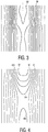
- FIGS. 3 and 4 represent the settlement the right half of the gradient coil in the direction of the axis of symmetry gradient (FIG. 3) and that coil of the active shield 8, which is traversed by the same current and which is the magnetic field of the gradient coil compensated for outside (Fig. 4). The transactions are on a different scale shown.
- the interconnects located next to each other in a single turn are through one Dash symbolizes. In reality, these traces are wider.
- the single ones The same current flows through windings one after the other in such a way that the turns or turn sections lying to the left of the plane of symmetry in this current flows in the same direction, while the windings or Turn sections on the right in the opposite direction from the current flow through, so that the desired gradient results.
- With conventional Coils have these coils in common that the number of turns 80 in the active Shielding coil (Fig. 3) is less than the number of turns 50 in the Gradient coil (Fig. 4).
- the coil is active Shield closer to the cryostat, so that to generate a magnetic field, the inside the cryostat is the same size - but in the opposite direction, like the magnetic field generated by the gradient coil a lower electrical Flooding or fewer turns are required.
- the individual turns are not in a plane perpendicular to the axis of symmetry (when looking at the outermost turns for which this is approximately the case) or they are not helical.
- winding loops 801..805 or 501 are formed, which are otherwise only found in Gradient coils with a gradient in a direction perpendicular to the axis of symmetry to be used. The number of turns is increased by these turns, and above (these turns are also above the table top) stronger than below.
- Windings 80 are closer to the coil in the active shield than below it Table top (see Fig. 1). There are therefore 8 more turns above the table top required or a higher electrical flow to the field of the gradient coil 5 to compensate.
- the coil of the active shielding above the table top has more turns than below and because the turns above are closer to Isocenter 10 are as the turns below, that is from the above lying turns in the isocent space generated stronger than that of the opposing field generated below turns.
- the gradient coil above the table top must also have more turns have as below and even if - as shown in Fig. 1 - the Isocenter 10 is located midway between the upper and lower turns.
- the ratio between the number of turns above and below is at Gradient coil smaller than the coil of the active shield.
Landscapes
- Physics & Mathematics (AREA)
- Condensed Matter Physics & Semiconductors (AREA)
- General Physics & Mathematics (AREA)
- Magnetic Resonance Imaging Apparatus (AREA)
- Coils Or Transformers For Communication (AREA)
Applications Claiming Priority (2)
| Application Number | Priority Date | Filing Date | Title |
|---|---|---|---|
| DE19953748 | 1999-11-09 | ||
| DE19953748A DE19953748A1 (de) | 1999-11-09 | 1999-11-09 | MR-Gerät |
Publications (3)
| Publication Number | Publication Date |
|---|---|
| EP1099954A2 true EP1099954A2 (fr) | 2001-05-16 |
| EP1099954A3 EP1099954A3 (fr) | 2003-03-26 |
| EP1099954B1 EP1099954B1 (fr) | 2006-11-29 |
Family
ID=7928343
Family Applications (1)
| Application Number | Title | Priority Date | Filing Date |
|---|---|---|---|
| EP00203794A Expired - Lifetime EP1099954B1 (fr) | 1999-11-09 | 2000-10-31 | Appareil de RM |
Country Status (4)
| Country | Link |
|---|---|
| US (1) | US6462636B1 (fr) |
| EP (1) | EP1099954B1 (fr) |
| JP (1) | JP2001170026A (fr) |
| DE (2) | DE19953748A1 (fr) |
Cited By (1)
| Publication number | Priority date | Publication date | Assignee | Title |
|---|---|---|---|---|
| WO2003052443A3 (fr) * | 2001-12-17 | 2003-12-24 | Koninkl Philips Electronics Nv | Ensemble bobine a gradient |
Families Citing this family (14)
| Publication number | Priority date | Publication date | Assignee | Title |
|---|---|---|---|---|
| DE10202986A1 (de) * | 2002-01-26 | 2003-07-31 | Philips Intellectual Property | Spulensystem für eine MR-Apparatur sowie MR-Apparatur mit einem solchen Spulensystem |
| JP4768627B2 (ja) * | 2003-11-18 | 2011-09-07 | コーニンクレッカ フィリップス エレクトロニクス エヌ ヴィ | 超高磁場(shf)mri用のrfコイル |
| US7345481B2 (en) * | 2003-11-18 | 2008-03-18 | Koninklijke Philips Electronics N.V. | Hybrid TEM/birdcage coil for MRI |
| WO2005088330A1 (fr) | 2004-03-03 | 2005-09-22 | Koninklijke Philips Electronics, N.V. | Bobine de gradient ultracourte asymetrique pour un systeme d'imagerie par resonance magnetique |
| DE102004040062B3 (de) * | 2004-08-18 | 2006-04-27 | Siemens Ag | Magnetresonanzgerät mit einer HF-Antenneneinheit und einer Gradientenspuleneinheit |
| DE102006050105A1 (de) * | 2006-10-24 | 2008-05-08 | Siemens Ag | Magnetresonanzanlage mit kreisförmigem Gradientensystem und nicht kreisförmiger Ganzkörperspule |
| CN102481116B (zh) | 2009-09-30 | 2015-02-18 | 株式会社日立医疗器械 | 倾斜磁场线圈以及磁共振成像装置 |
| JP5202491B2 (ja) * | 2009-09-30 | 2013-06-05 | 株式会社日立メディコ | 磁気共鳴イメージング装置 |
| JP5204813B2 (ja) * | 2010-08-06 | 2013-06-05 | 株式会社日立メディコ | 傾斜磁場コイル、及び、磁気共鳴イメージング装置 |
| US9389291B2 (en) * | 2009-11-27 | 2016-07-12 | Hitachi Medical Corporation | Gradient coil, magnetic resonance imaging device, and method for designing coil pattern |
| US8169220B2 (en) * | 2009-12-15 | 2012-05-01 | General Electric Company | Flattened gradient coil for MRI systems |
| JP5248557B2 (ja) * | 2010-07-29 | 2013-07-31 | ジーイー・メディカル・システムズ・グローバル・テクノロジー・カンパニー・エルエルシー | 磁気共鳴イメージング装置 |
| KR101525013B1 (ko) | 2012-11-05 | 2015-06-16 | 삼성전자주식회사 | 자기공명영상 장치 |
| CN105074489B (zh) * | 2013-03-28 | 2019-02-15 | 皇家飞利浦有限公司 | 针对可变患者尺寸的多区域射频线圈阵列 |
Family Cites Families (3)
| Publication number | Priority date | Publication date | Assignee | Title |
|---|---|---|---|---|
| US4820988A (en) * | 1987-10-07 | 1989-04-11 | The Regents Of The University Of California | Magnetic gradient coil set for nuclear magnetic resonace system having substantially different coil-patient spacings |
| US5543711A (en) * | 1994-11-22 | 1996-08-06 | Picker International, Inc. | Multiple quadrature volume coils for magnetic resonance imaging |
| DE19504171C2 (de) * | 1995-02-07 | 1998-04-30 | Siemens Ag | Trennbare, lokale Gradientenspulenanordnung für Kernspintomographiegeräte |
-
1999
- 1999-11-09 DE DE19953748A patent/DE19953748A1/de not_active Withdrawn
-
2000
- 2000-10-31 EP EP00203794A patent/EP1099954B1/fr not_active Expired - Lifetime
- 2000-10-31 DE DE50013809T patent/DE50013809D1/de not_active Expired - Lifetime
- 2000-11-08 JP JP2000340952A patent/JP2001170026A/ja not_active Withdrawn
- 2000-11-09 US US09/709,268 patent/US6462636B1/en not_active Expired - Fee Related
Cited By (1)
| Publication number | Priority date | Publication date | Assignee | Title |
|---|---|---|---|---|
| WO2003052443A3 (fr) * | 2001-12-17 | 2003-12-24 | Koninkl Philips Electronics Nv | Ensemble bobine a gradient |
Also Published As
| Publication number | Publication date |
|---|---|
| DE19953748A1 (de) | 2001-05-10 |
| EP1099954B1 (fr) | 2006-11-29 |
| JP2001170026A (ja) | 2001-06-26 |
| DE50013809D1 (de) | 2007-01-11 |
| EP1099954A3 (fr) | 2003-03-26 |
| US6462636B1 (en) | 2002-10-08 |
Similar Documents
| Publication | Publication Date | Title |
|---|---|---|
| DE4424580C2 (de) | NMR-Scheibenspule | |
| EP0586983B1 (fr) | Système de bobines à gradients pour un tomographe thérapeutique | |
| DE102008006117B4 (de) | Magnetresonanzanlage, Antennensystem, Verfahren zum Aufbau einer Magnetresonanzanlage und Verfahren zur Erzeugung von Magnetresonanzaufnahmen | |
| EP1099954B1 (fr) | Appareil de RM | |
| DE4422782C2 (de) | Aktiv geschirmte transversale Gradientenspule für Kernspintomographiegeräte | |
| DE3875863T2 (de) | Magnetisches resonanzgeraet mit gradientenspulensystem. | |
| DE3511750A1 (de) | Spulenanordnung fuer kernspinuntersuchungen | |
| DE102008004410A1 (de) | Luftspule mit hohem Qualitätsfaktor und geringen Ausmaßen | |
| DE4142263C2 (de) | Gradientenspulensystem | |
| EP0361190A1 (fr) | Dispositif de bobines de surface pour examens par résonance magnétique nucléaire | |
| DE102013216376B4 (de) | Antenneneinrichtung zum Empfang von Magnetresonanzsignalen | |
| DE69215114T2 (de) | Magnet-Vorrichtung zur Erzeugung eines statischen Magnetfeldes bei der Bildgebung mittels magnetischer Resonanz | |
| EP3555648B1 (fr) | Système à antennes dipôles pour la capture d'images au moyen de méthodes de résonance magnétique nucléaire | |
| WO2012156278A1 (fr) | Dispositif de production d'un champ magnétique homogène | |
| DE3514819A1 (de) | Magnetfelderzeugungs-spule fuer ein mit kernmagnetischer resonanz arbeitendes abbildungsgeraet | |
| DE102004024098B4 (de) | Erzeuger zeitvariabler Magnetfelder für ein Magnetresonanzgerät und Magnetresonanzgerät mit einem derartigen Erzeuger zeitvariabler Magnetfelder | |
| DE19527020C1 (de) | Tesserale Gradientenspule für Kernspintomographiegeräte | |
| DE3800908A1 (de) | Ein kompakter quergradienten-magnetspulenaufbau fuer eine magnetische resonanzspektroskopie-anlage | |
| EP0238909B1 (fr) | Aimant de champ principal dans un arrangement pour la production d'images par la technique à résonance magnétique nucléaire | |
| EP1233279A2 (fr) | Dispositif d'imagerie à résonance magnétique avec un système magnétique ouvert | |
| DE3417392A1 (de) | Fernseh-bildwiedergabegeraet mit einrichtung zur rasterkorrektur | |
| DE19545222C2 (de) | Gradientenspulen für Therapietomographen | |
| DE69332568T2 (de) | Magnetstruktur mit partiellen joch und magnetischem nebenschluss | |
| DE60225039T2 (de) | Rf-spule mit zwei parallelen endleitern | |
| DE19503833C2 (de) | Kernspintomographiegerät mit einer Kombination aus Hochfrequenzantenne und Gradientenspule |
Legal Events
| Date | Code | Title | Description |
|---|---|---|---|
| PUAI | Public reference made under article 153(3) epc to a published international application that has entered the european phase |
Free format text: ORIGINAL CODE: 0009012 |
|
| AK | Designated contracting states |
Kind code of ref document: A2 Designated state(s): AT BE CH CY DE DK ES FI FR GB GR IE IT LI LU MC NL PT SE |
|
| AX | Request for extension of the european patent |
Free format text: AL;LT;LV;MK;RO;SI |
|
| RAP1 | Party data changed (applicant data changed or rights of an application transferred) |
Owner name: PHILIPS CORPORATE INTELLECTUAL PROPERTY GMBH Owner name: KONINKLIJKE PHILIPS ELECTRONICS N.V. |
|
| PUAL | Search report despatched |
Free format text: ORIGINAL CODE: 0009013 |
|
| AK | Designated contracting states |
Kind code of ref document: A3 Designated state(s): AT BE CH CY DE DK ES FI FR GB GR IE IT LI LU MC NL PT SE |
|
| AX | Request for extension of the european patent |
Extension state: AL LT LV MK RO SI |
|
| RAP1 | Party data changed (applicant data changed or rights of an application transferred) |
Owner name: PHILIPS INTELLECTUAL PROPERTY & STANDARDS GMBH Owner name: KONINKLIJKE PHILIPS ELECTRONICS N.V. |
|
| 17P | Request for examination filed |
Effective date: 20030926 |
|
| AKX | Designation fees paid |
Designated state(s): DE FR GB NL |
|
| GRAP | Despatch of communication of intention to grant a patent |
Free format text: ORIGINAL CODE: EPIDOSNIGR1 |
|
| GRAS | Grant fee paid |
Free format text: ORIGINAL CODE: EPIDOSNIGR3 |
|
| GRAA | (expected) grant |
Free format text: ORIGINAL CODE: 0009210 |
|
| AK | Designated contracting states |
Kind code of ref document: B1 Designated state(s): DE FR GB NL |
|
| PG25 | Lapsed in a contracting state [announced via postgrant information from national office to epo] |
Ref country code: NL Free format text: LAPSE BECAUSE OF FAILURE TO SUBMIT A TRANSLATION OF THE DESCRIPTION OR TO PAY THE FEE WITHIN THE PRESCRIBED TIME-LIMIT Effective date: 20061129 |
|
| REG | Reference to a national code |
Ref country code: GB Ref legal event code: FG4D Free format text: NOT ENGLISH |
|
| REF | Corresponds to: |
Ref document number: 50013809 Country of ref document: DE Date of ref document: 20070111 Kind code of ref document: P |
|
| NLV1 | Nl: lapsed or annulled due to failure to fulfill the requirements of art. 29p and 29m of the patents act | ||
| ET | Fr: translation filed | ||
| GBV | Gb: ep patent (uk) treated as always having been void in accordance with gb section 77(7)/1977 [no translation filed] |
Effective date: 20061129 |
|
| PLBE | No opposition filed within time limit |
Free format text: ORIGINAL CODE: 0009261 |
|
| STAA | Information on the status of an ep patent application or granted ep patent |
Free format text: STATUS: NO OPPOSITION FILED WITHIN TIME LIMIT |
|
| 26N | No opposition filed |
Effective date: 20070830 |
|
| PG25 | Lapsed in a contracting state [announced via postgrant information from national office to epo] |
Ref country code: GB Free format text: LAPSE BECAUSE OF FAILURE TO SUBMIT A TRANSLATION OF THE DESCRIPTION OR TO PAY THE FEE WITHIN THE PRESCRIBED TIME-LIMIT Effective date: 20061129 |
|
| PGFP | Annual fee paid to national office [announced via postgrant information from national office to epo] |
Ref country code: DE Payment date: 20091229 Year of fee payment: 10 |
|
| REG | Reference to a national code |
Ref country code: DE Ref legal event code: R119 Ref document number: 50013809 Country of ref document: DE Effective date: 20110502 |
|
| PGFP | Annual fee paid to national office [announced via postgrant information from national office to epo] |
Ref country code: FR Payment date: 20121128 Year of fee payment: 13 |
|
| PG25 | Lapsed in a contracting state [announced via postgrant information from national office to epo] |
Ref country code: DE Free format text: LAPSE BECAUSE OF NON-PAYMENT OF DUE FEES Effective date: 20110502 |
|
| REG | Reference to a national code |
Ref country code: FR Ref legal event code: ST Effective date: 20140630 |
|
| PG25 | Lapsed in a contracting state [announced via postgrant information from national office to epo] |
Ref country code: FR Free format text: LAPSE BECAUSE OF NON-PAYMENT OF DUE FEES Effective date: 20131031 |