EP1100139A1 - Batterie enroulée - Google Patents
Batterie enroulée Download PDFInfo
- Publication number
- EP1100139A1 EP1100139A1 EP99811044A EP99811044A EP1100139A1 EP 1100139 A1 EP1100139 A1 EP 1100139A1 EP 99811044 A EP99811044 A EP 99811044A EP 99811044 A EP99811044 A EP 99811044A EP 1100139 A1 EP1100139 A1 EP 1100139A1
- Authority
- EP
- European Patent Office
- Prior art keywords
- arrester
- battery
- battery according
- winding
- area
- Prior art date
- Legal status (The legal status is an assumption and is not a legal conclusion. Google has not performed a legal analysis and makes no representation as to the accuracy of the status listed.)
- Granted
Links
Images


Classifications
-
- H—ELECTRICITY
- H01—ELECTRIC ELEMENTS
- H01M—PROCESSES OR MEANS, e.g. BATTERIES, FOR THE DIRECT CONVERSION OF CHEMICAL ENERGY INTO ELECTRICAL ENERGY
- H01M10/00—Secondary cells; Manufacture thereof
- H01M10/04—Construction or manufacture in general
- H01M10/0431—Cells with wound or folded electrodes
-
- H—ELECTRICITY
- H01—ELECTRIC ELEMENTS
- H01M—PROCESSES OR MEANS, e.g. BATTERIES, FOR THE DIRECT CONVERSION OF CHEMICAL ENERGY INTO ELECTRICAL ENERGY
- H01M10/00—Secondary cells; Manufacture thereof
- H01M10/05—Accumulators with non-aqueous electrolyte
- H01M10/052—Li-accumulators
- H01M10/0525—Rocking-chair batteries, i.e. batteries with lithium insertion or intercalation in both electrodes; Lithium-ion batteries
-
- H—ELECTRICITY
- H01—ELECTRIC ELEMENTS
- H01M—PROCESSES OR MEANS, e.g. BATTERIES, FOR THE DIRECT CONVERSION OF CHEMICAL ENERGY INTO ELECTRICAL ENERGY
- H01M6/00—Primary cells; Manufacture thereof
- H01M6/04—Cells with aqueous electrolyte
- H01M6/06—Dry cells, i.e. cells wherein the electrolyte is rendered non-fluid
- H01M6/10—Dry cells, i.e. cells wherein the electrolyte is rendered non-fluid with wound or folded electrodes
- H01M2006/106—Elliptic wound cells
-
- H—ELECTRICITY
- H01—ELECTRIC ELEMENTS
- H01M—PROCESSES OR MEANS, e.g. BATTERIES, FOR THE DIRECT CONVERSION OF CHEMICAL ENERGY INTO ELECTRICAL ENERGY
- H01M4/00—Electrodes
- H01M4/02—Electrodes composed of, or comprising, active material
- H01M4/64—Carriers or collectors
-
- Y—GENERAL TAGGING OF NEW TECHNOLOGICAL DEVELOPMENTS; GENERAL TAGGING OF CROSS-SECTIONAL TECHNOLOGIES SPANNING OVER SEVERAL SECTIONS OF THE IPC; TECHNICAL SUBJECTS COVERED BY FORMER USPC CROSS-REFERENCE ART COLLECTIONS [XRACs] AND DIGESTS
- Y02—TECHNOLOGIES OR APPLICATIONS FOR MITIGATION OR ADAPTATION AGAINST CLIMATE CHANGE
- Y02E—REDUCTION OF GREENHOUSE GAS [GHG] EMISSIONS, RELATED TO ENERGY GENERATION, TRANSMISSION OR DISTRIBUTION
- Y02E60/00—Enabling technologies; Technologies with a potential or indirect contribution to GHG emissions mitigation
- Y02E60/10—Energy storage using batteries
-
- Y—GENERAL TAGGING OF NEW TECHNOLOGICAL DEVELOPMENTS; GENERAL TAGGING OF CROSS-SECTIONAL TECHNOLOGIES SPANNING OVER SEVERAL SECTIONS OF THE IPC; TECHNICAL SUBJECTS COVERED BY FORMER USPC CROSS-REFERENCE ART COLLECTIONS [XRACs] AND DIGESTS
- Y02—TECHNOLOGIES OR APPLICATIONS FOR MITIGATION OR ADAPTATION AGAINST CLIMATE CHANGE
- Y02P—CLIMATE CHANGE MITIGATION TECHNOLOGIES IN THE PRODUCTION OR PROCESSING OF GOODS
- Y02P70/00—Climate change mitigation technologies in the production process for final industrial or consumer products
- Y02P70/50—Manufacturing or production processes characterised by the final manufactured product
Definitions
- the invention relates to a battery with at least one pin-shaped conductor inside a winding and an arrester band attached to the arrester with a connection area with an active surface coating.
- High energy densities can be achieved with wound batteries, e.g. in the EP 0 144 757, JP 57-163965 or US 5,556,722 are described.
- a dense Housing is a "jelly roll" with an active cathode and an active Anode strap housed.
- the spirally wound tapes are electrically separated by a separator, being a liquid electrolyte or a polymer serves as an ion conductor. Electrical conductors connect the tapes to the outside of the housing Power connections (negative and positive pole of the battery).
- active materials are usually based on metallic arrester foils made of aluminum for the cathode (Co, Mn, Ni) and made of copper for the anode (graphite, coke).
- metallic arrester foils made of aluminum for the cathode (Co, Mn, Ni) and made of copper for the anode (graphite, coke).
- the object of the invention is to provide a battery of the type mentioned at which is the active band length of the cathode and anode as large as possible without problems arise with undesirable deposits of the type mentioned.
- the solution to the problem is defined by the features of claim 1.
- the pin-shaped arrester subsequent to the connection area with at least a winding of the arrester band immediately enclosed.
- connection area is preferably as small as possible. In particular, it should be less claim as half a peripheral area of the arrester. With cylindrical arresters does it extend e.g. only just over a quarter (i.e. 90 ° in relation to the longitudinal axis of the arrester).
- two arrester bands are used, which are designed as a cathode and anode tape.
- Known materials can include aluminum strips for the cathode and copper strips for the anode can be used. Batteries with other basic chemical reactions can accordingly other materials are used.
- Electrolyte-soaked separator tapes are wound between the arrester tapes. At least one continuous band is required. But it is also conceivable that e.g. ever a separate separator band is assigned to each arrester.
- the arrester has the shape of a Tube, inside of which is a so-called integrated power connector is trained. At least part of the inside of the tube is accessible from the outside and forms the cavity as a power connection for a plug element of a holder.
- the So arresters form the female part of a connector, so that the battery a suitably trained male part can be put on, not only the electrical contact is established, but at the same time the mechanical holding of the battery.
- the battery is box-shaped or cuboid and has exactly two winding bars with internal plug connections according to the invention on.
- the winding bars are in the turning points of the flat winding and have a diameter of e.g. less than 2 mm (typically about 1 mm).
- a flat winding plate can also be provided two cavities accessible from outside the battery housing as power connections Has.
- the Represent power connections are the additional required with known batteries electrical connecting elements to connections arranged on the outside of the housing lapsed.
- the cavity through the Housing extends through. This means that it is accessible from two (opposite) sides. In this way it becomes possible to connect batteries in series in the smallest space or batteries as optional intermediate elements between a device connection and a power supply.
- the cavity does not have to be continuous. He can e.g. somewhere inside have a partition that has direct mechanical contact between one of "below” and a plug inserted from “above” or a stop for forms a contact pin inserted from the outside.
- the cavity will at least overlap extend a third, preferably over more than half of the length mentioned.
- the cavity is relatively larger than in large ones (stability of the Contact pins).
- the arresters are close to each other in the center of the winding.
- the The battery can then have a more or less cylindrical shape overall.
- the distance the arrester is, for example, just large enough for the wrapping windings according to the invention Have space. The distance can therefore be less than 1 mm.
- the first embodiments mentioned were characterized in that between there are tapes with active surface coating in the arresters. So there is no inactive storage area between the arresters. The one in the housing existing space is optimally used for power generation.
- the arresters have a proportional one large distance from each other so that the battery is flat overall.
- a distance is in referred to in this context as large if it is larger than a thickness of the winding.
- the housing is in the area between the arresters shaped in such a way (or pressed flat) that there is no free space in the center of the winding is. The two halves of the roll lie on top of each other in the center.
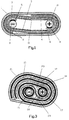
- housing 1 In a hermetically sealed, e.g. rounded / flattened housing 1 is a Coil 2 of anode tape 3, cathode tape 4 and separator tapes 5, 6 housed. (The separator strips 5, 6 are impregnated with electrolyte as usual.) Anode strips 3 and Cathode strips 4 are provided with an active coating on both sides and are kept separate by the separator belts 5, 6. Inside the coil 2 are two e.g. pin-shaped carrier 9, 10 are provided. The anode strip 3 is with its connection area 7 e.g. on the first carrier 9 and the cathode strip 4 with its connection area 8 on the second Beam 10 spot welded. The battery current can thus over the drain off both carriers 9, 10.
- cathode strip 12 is on both sides an active coating 14.1, 14.2.
- the length of the connection area 13 is e.g. just about 1-3 mm.
- the cathode strip 12 is in the connection area 13 uncoated on both sides. In principle, however, it is sufficient if the active coating only missing on the inner side, i.e. where the cathode strip 12 is on the tube 15 (arrester) is attached.
- connection area 13 is now electrically conductive with a Tube 15 connected (Fig. 2a).
- This tube 15 represents one of two carriers of the battery pack.
- the tube 15 is rotated (Fig. 2b) until at least one closed wrap through the cathode strip 12 is present (Fig. 2c).
- the non-coated connection area 13 is through the subsequent, coated part of the cathode strip 12 covered.
- Fig. 3 shows the finished battery.
- the two carriers 15 and 17 at a small mutual distance (from e.g. less than a diameter of a carrier 15 or 17) arranged.
- In the area 20 between The two supports 15 and 17 contain electrolyte 29. That between the two Carriers 15 and 17 running separator belt 19 creates a (shown in dashed lines) additional active area 28.
- the space in the housing 21 is thus better utilized than in the prior art (according to FIG. 1).
- Pre-winding" of the carriers 15 and 17 inhibits self-discharge.
- Fig. 4 shows a further embodiment, which is characterized by a particularly flat design distinguished.
- the two carriers of the winding 24 are formed by tubes 22, 23. she are housed at a large mutual distance in a flat housing 27.
- the structure of the winding 24 is in principle the same as explained with reference to FIGS. 2a to 2d.
- Each tube 22, 23 is therefore at least once directly with the respective arrester band wrapped before the common wrapping of both tubes 22, 23 takes place.
- the housing 27 is in accordance with a particularly preferred embodiment pressed inwards.
- the thickness D of the battery is less than at the ends of the two tubes 22 and 23 (where a kind of cylindrical beads are formed by the housing).
- the housing 27 is typically according to the diameter d a tube 22 or 23 larger (namely d + D). Small batteries become tubes used with a diameter d ⁇ 2 mm.
- the winding 24 is also corresponding thin.
- the length of the area 25 can be several millimeters to more than one centimeter depending on the required capacity of the battery.
- the housing 21 is only pressed in on one side in the region 25.
- the other (opposite) side runs without indentation.
- This can be used for other purposes.
- housing a circuit for controlling the power supply. Is the Rechargeable battery, the control electronics of the charger can be in the well mentioned be accommodated.
- the invention is related to miniaturized Devices used, the exact shape of the battery and the design of the device or the battery holder according to each other's needs be coordinated.
- the housing 27 is equipped with an edge coupling 30.
- a housing part 31 can be coupled.
- the battery can, so to speak Form the bottom of a device.
- the housing part 31 e.g. also one Circuit board to be attached to the battery.
- the inside of the tubes 22, 23 the power connections of the battery are provided.
- the tubes are at the ends open for appropriately trained contact pins of a holder.
- the contact pins serve at the same time to hold the battery mechanically. This way one can be special reliable electrical contact can be ensured.
- the battery holder be simple and inexpensive. And overall the space is minimized which is typically required for the overall arrangement "holder + battery" becomes.
- FIG. 5 differs from that according to FIG. 3 essentially in that only one of the two supports 32, 33 is designed as a tube.
- the other carrier 32 is a thin, closed pin.
- the battery can therefore be brought into an almost cylindrical shape.
- the other parts of the battery already described in connection with FIG. 3 are: double-sided coated cathode strip 34 and double-sided anode strip 35, separator strip 36 coated with electrolyte 37, additionally active area 38.
- the exemplary embodiments described can be modified in a variety of ways. There are not only minimum or maximum, but also medium distances between the arresters possible. For example, the distance in the embodiment according to FIG. 3 is increased in this way that there is space for another tube between the two arresters, which is designed as a current feedthrough. I.e. the third tube mentioned is not in electrical contact with the poles of the battery or the electrochemically active area, but represents an isolated implementation for other purposes (e.g. um two components that are separated by the battery, electrical connect with each other).
- the battery shown in Fig. 4 can e.g. in the form of the space available to anyone Device can be adjusted. Instead of making the area 25 flat, it can be cylindrical be curved (according to the cylindrical shape of the device of interest).
- the indentation need not only be formed on one side. It can two symmetrical or asymmetrical indentations can also be produced.
Landscapes
- Engineering & Computer Science (AREA)
- Manufacturing & Machinery (AREA)
- Chemical & Material Sciences (AREA)
- Chemical Kinetics & Catalysis (AREA)
- Electrochemistry (AREA)
- General Chemical & Material Sciences (AREA)
- Primary Cells (AREA)
- Connection Of Batteries Or Terminals (AREA)
Priority Applications (1)
| Application Number | Priority Date | Filing Date | Title |
|---|---|---|---|
| EP99811044.9A EP1100139B1 (fr) | 1999-11-12 | 1999-11-12 | Batterie enroulée |
Applications Claiming Priority (1)
| Application Number | Priority Date | Filing Date | Title |
|---|---|---|---|
| EP99811044.9A EP1100139B1 (fr) | 1999-11-12 | 1999-11-12 | Batterie enroulée |
Publications (2)
| Publication Number | Publication Date |
|---|---|
| EP1100139A1 true EP1100139A1 (fr) | 2001-05-16 |
| EP1100139B1 EP1100139B1 (fr) | 2015-12-09 |
Family
ID=8243140
Family Applications (1)
| Application Number | Title | Priority Date | Filing Date |
|---|---|---|---|
| EP99811044.9A Expired - Lifetime EP1100139B1 (fr) | 1999-11-12 | 1999-11-12 | Batterie enroulée |
Country Status (1)
| Country | Link |
|---|---|
| EP (1) | EP1100139B1 (fr) |
Cited By (3)
| Publication number | Priority date | Publication date | Assignee | Title |
|---|---|---|---|---|
| WO2006077192A1 (fr) * | 2005-01-20 | 2006-07-27 | Oticon A/S | Prothese auditive comprenant une batterie rechargeable et batterie rechargeable |
| EP2706592A1 (fr) | 2012-09-11 | 2014-03-12 | swissbatt AG | Batterie avec structure à positionnement précis |
| EP2822057A1 (fr) * | 2013-07-04 | 2015-01-07 | Wyon AG | Batterie à structure enroulée |
Citations (3)
| Publication number | Priority date | Publication date | Assignee | Title |
|---|---|---|---|---|
| US2473546A (en) * | 1943-01-23 | 1949-06-21 | Ruben Samuel | Alkaline primary cell |
| GB1144438A (en) * | 1965-05-07 | 1969-03-05 | Bosch Gmbh Robert | Improvements in or relating to electrical storage batteries |
| DE2137753A1 (de) * | 1970-08-03 | 1972-02-10 | Gates Rubber Co | Alkalische elektrochemische Zelle |
-
1999
- 1999-11-12 EP EP99811044.9A patent/EP1100139B1/fr not_active Expired - Lifetime
Patent Citations (3)
| Publication number | Priority date | Publication date | Assignee | Title |
|---|---|---|---|---|
| US2473546A (en) * | 1943-01-23 | 1949-06-21 | Ruben Samuel | Alkaline primary cell |
| GB1144438A (en) * | 1965-05-07 | 1969-03-05 | Bosch Gmbh Robert | Improvements in or relating to electrical storage batteries |
| DE2137753A1 (de) * | 1970-08-03 | 1972-02-10 | Gates Rubber Co | Alkalische elektrochemische Zelle |
Cited By (7)
| Publication number | Priority date | Publication date | Assignee | Title |
|---|---|---|---|---|
| WO2006077192A1 (fr) * | 2005-01-20 | 2006-07-27 | Oticon A/S | Prothese auditive comprenant une batterie rechargeable et batterie rechargeable |
| CN101107736B (zh) * | 2005-01-20 | 2010-05-26 | 奥迪康有限公司 | 具有可再充电电池的助听器及可再充电电池 |
| AU2006207557B2 (en) * | 2005-01-20 | 2010-07-22 | Oticon A/S | Hearing aid with rechargeable battery and rechargeable battery |
| US8224007B2 (en) | 2005-01-20 | 2012-07-17 | Oticon A/S | Hearing aid with rechargeable battery and rechargeable battery |
| EP2706592A1 (fr) | 2012-09-11 | 2014-03-12 | swissbatt AG | Batterie avec structure à positionnement précis |
| US11605835B2 (en) | 2012-09-11 | 2023-03-14 | Swissbatt Ag | Battery with a precisely positioned construction |
| EP2822057A1 (fr) * | 2013-07-04 | 2015-01-07 | Wyon AG | Batterie à structure enroulée |
Also Published As
| Publication number | Publication date |
|---|---|
| EP1100139B1 (fr) | 2015-12-09 |
Similar Documents
| Publication | Publication Date | Title |
|---|---|---|
| EP3041062B1 (fr) | Cellule électrochimique | |
| DE69709643T2 (de) | Elektrochemische zelle | |
| DE60011413T2 (de) | Luft-gestützte elektrochemische zellenkonstruktion | |
| DE69524894T2 (de) | Prismatische hochleistungsfähige Zelle | |
| EP1011163B1 (fr) | Accumulateur électrique sous forme bouton | |
| EP3032611B1 (fr) | Batterie avec structure a positionnement precis | |
| DE69800740T2 (de) | Elektrochemischer Generator mit korrosionsgeschütztem isoliertem Gehäuse | |
| DE69432392T2 (de) | Elektrochemische Zelle mit hoher Zuverlässigkeit und Elektrodenanordnung hierfür | |
| WO2022023321A1 (fr) | Cellule de stockage d'énergie et procédé de production | |
| DE102010031543A1 (de) | Batterie, ein Bimetall enthaltend | |
| WO2018059967A1 (fr) | Procédé de fabrication d'une pile d'électrodes pour un élément de batterie et élément de batterie | |
| EP3457453A1 (fr) | Accumulateur et son procédé de fabrication | |
| DE1671925A1 (de) | Elektrochemischer Generator mit einem zylinderringfoermigen Gehaeuse | |
| DE69905574T2 (de) | Elektrochemische zelle mit grosser mündung an der gehäuseöffnung | |
| DE3586223T2 (de) | Herstellungsmethode einer gasdichtverschlossenen metalloxid-wasserstoffspeicherzelle. | |
| DE69608686T2 (de) | Gewickelte elektrochemische zelle, herstellungsverfahren und verwendung der zelle | |
| EP3284119A1 (fr) | Batterie comprenant un boîtier métallique prismatique | |
| DE19606879A1 (de) | Verfahren zur Herstellung einer alkalischen Sekundärbatterie, Pluselektrode dafür und hauptgeladene alkalische Sekundärbatterie | |
| WO2021219732A1 (fr) | Pile électrochimique au lithium-ion secondaire | |
| EP1100139B1 (fr) | Batterie enroulée | |
| EP1100138B1 (fr) | Pile et support de fixation de la pile | |
| DE68906071T2 (de) | Methode zur Herstellung einer gasdicht verschlossenen elektrochemischen Zelle. | |
| DE102020210288A1 (de) | Elektroden für erhöhte benetzbarkeit | |
| DE952282C (de) | Staendig gasdicht verschlossene Akkumulatorenzelle mit spiralig gewickelten Elektroden, insbesondere Sintergeruestfolien-Elektroden | |
| DE102014219636A1 (de) | Batterie und Verfahren zur Herstellung einer Batterie |
Legal Events
| Date | Code | Title | Description |
|---|---|---|---|
| PUAI | Public reference made under article 153(3) epc to a published international application that has entered the european phase |
Free format text: ORIGINAL CODE: 0009012 |
|
| AK | Designated contracting states |
Kind code of ref document: A1 Designated state(s): AT BE CH CY DE DK ES FI FR GB GR IE IT LI LU MC NL PT SE |
|
| AX | Request for extension of the european patent |
Free format text: AL;LT;LV;MK;RO;SI |
|
| 17P | Request for examination filed |
Effective date: 20010620 |
|
| AKX | Designation fees paid |
Free format text: AT BE CH CY DE DK ES FI FR GB GR IE IT LI LU MC NL PT SE |
|
| 17Q | First examination report despatched |
Effective date: 20080513 |
|
| GRAP | Despatch of communication of intention to grant a patent |
Free format text: ORIGINAL CODE: EPIDOSNIGR1 |
|
| RIC1 | Information provided on ipc code assigned before grant |
Ipc: H01M 4/64 20060101ALI20150616BHEP Ipc: H01M 6/10 20060101AFI20150616BHEP |
|
| INTG | Intention to grant announced |
Effective date: 20150708 |
|
| RAP1 | Party data changed (applicant data changed or rights of an application transferred) |
Owner name: WYON AG |
|
| RIN1 | Information on inventor provided before grant (corrected) |
Inventor name: WYSER, PAUL JULIAN |
|
| GRAS | Grant fee paid |
Free format text: ORIGINAL CODE: EPIDOSNIGR3 |
|
| GRAA | (expected) grant |
Free format text: ORIGINAL CODE: 0009210 |
|
| AK | Designated contracting states |
Kind code of ref document: B1 Designated state(s): AT BE CH CY DE DK ES FI FR GB GR IE IT LI LU MC NL PT SE |
|
| REG | Reference to a national code |
Ref country code: GB Ref legal event code: FG4D Free format text: NOT ENGLISH |
|
| REG | Reference to a national code |
Ref country code: AT Ref legal event code: REF Ref document number: 764912 Country of ref document: AT Kind code of ref document: T Effective date: 20151215 Ref country code: CH Ref legal event code: EP |
|
| REG | Reference to a national code |
Ref country code: IE Ref legal event code: FG4D Free format text: LANGUAGE OF EP DOCUMENT: GERMAN |
|
| REG | Reference to a national code |
Ref country code: CH Ref legal event code: NV Representative=s name: KELLER AND PARTNER PATENTANWAELTE AG, CH |
|
| REG | Reference to a national code |
Ref country code: DE Ref legal event code: R096 Ref document number: 59915438 Country of ref document: DE |
|
| REG | Reference to a national code |
Ref country code: NL Ref legal event code: MP Effective date: 20151209 |
|
| PG25 | Lapsed in a contracting state [announced via postgrant information from national office to epo] |
Ref country code: ES Free format text: LAPSE BECAUSE OF FAILURE TO SUBMIT A TRANSLATION OF THE DESCRIPTION OR TO PAY THE FEE WITHIN THE PRESCRIBED TIME-LIMIT Effective date: 20151209 |
|
| PG25 | Lapsed in a contracting state [announced via postgrant information from national office to epo] |
Ref country code: GR Free format text: LAPSE BECAUSE OF FAILURE TO SUBMIT A TRANSLATION OF THE DESCRIPTION OR TO PAY THE FEE WITHIN THE PRESCRIBED TIME-LIMIT Effective date: 20160310 Ref country code: FI Free format text: LAPSE BECAUSE OF FAILURE TO SUBMIT A TRANSLATION OF THE DESCRIPTION OR TO PAY THE FEE WITHIN THE PRESCRIBED TIME-LIMIT Effective date: 20151209 Ref country code: SE Free format text: LAPSE BECAUSE OF FAILURE TO SUBMIT A TRANSLATION OF THE DESCRIPTION OR TO PAY THE FEE WITHIN THE PRESCRIBED TIME-LIMIT Effective date: 20151209 Ref country code: NL Free format text: LAPSE BECAUSE OF FAILURE TO SUBMIT A TRANSLATION OF THE DESCRIPTION OR TO PAY THE FEE WITHIN THE PRESCRIBED TIME-LIMIT Effective date: 20151209 |
|
| PG25 | Lapsed in a contracting state [announced via postgrant information from national office to epo] |
Ref country code: IT Free format text: LAPSE BECAUSE OF FAILURE TO SUBMIT A TRANSLATION OF THE DESCRIPTION OR TO PAY THE FEE WITHIN THE PRESCRIBED TIME-LIMIT Effective date: 20151209 |
|
| PG25 | Lapsed in a contracting state [announced via postgrant information from national office to epo] |
Ref country code: PT Free format text: LAPSE BECAUSE OF FAILURE TO SUBMIT A TRANSLATION OF THE DESCRIPTION OR TO PAY THE FEE WITHIN THE PRESCRIBED TIME-LIMIT Effective date: 20160411 |
|
| REG | Reference to a national code |
Ref country code: DE Ref legal event code: R097 Ref document number: 59915438 Country of ref document: DE |
|
| PLBE | No opposition filed within time limit |
Free format text: ORIGINAL CODE: 0009261 |
|
| STAA | Information on the status of an ep patent application or granted ep patent |
Free format text: STATUS: NO OPPOSITION FILED WITHIN TIME LIMIT |
|
| REG | Reference to a national code |
Ref country code: FR Ref legal event code: PLFP Year of fee payment: 18 |
|
| PG25 | Lapsed in a contracting state [announced via postgrant information from national office to epo] |
Ref country code: DK Free format text: LAPSE BECAUSE OF FAILURE TO SUBMIT A TRANSLATION OF THE DESCRIPTION OR TO PAY THE FEE WITHIN THE PRESCRIBED TIME-LIMIT Effective date: 20151209 |
|
| 26N | No opposition filed |
Effective date: 20160912 |
|
| PG25 | Lapsed in a contracting state [announced via postgrant information from national office to epo] |
Ref country code: BE Free format text: LAPSE BECAUSE OF NON-PAYMENT OF DUE FEES Effective date: 20161130 |
|
| GBPC | Gb: european patent ceased through non-payment of renewal fee |
Effective date: 20161112 |
|
| REG | Reference to a national code |
Ref country code: IE Ref legal event code: MM4A |
|
| PG25 | Lapsed in a contracting state [announced via postgrant information from national office to epo] |
Ref country code: LU Free format text: LAPSE BECAUSE OF NON-PAYMENT OF DUE FEES Effective date: 20161130 |
|
| REG | Reference to a national code |
Ref country code: FR Ref legal event code: PLFP Year of fee payment: 19 |
|
| PG25 | Lapsed in a contracting state [announced via postgrant information from national office to epo] |
Ref country code: GB Free format text: LAPSE BECAUSE OF NON-PAYMENT OF DUE FEES Effective date: 20161112 Ref country code: IE Free format text: LAPSE BECAUSE OF NON-PAYMENT OF DUE FEES Effective date: 20161112 |
|
| REG | Reference to a national code |
Ref country code: AT Ref legal event code: MM01 Ref document number: 764912 Country of ref document: AT Kind code of ref document: T Effective date: 20161112 |
|
| PG25 | Lapsed in a contracting state [announced via postgrant information from national office to epo] |
Ref country code: AT Free format text: LAPSE BECAUSE OF NON-PAYMENT OF DUE FEES Effective date: 20161112 |
|
| REG | Reference to a national code |
Ref country code: BE Ref legal event code: MM Effective date: 20161130 |
|
| PG25 | Lapsed in a contracting state [announced via postgrant information from national office to epo] |
Ref country code: CY Free format text: LAPSE BECAUSE OF FAILURE TO SUBMIT A TRANSLATION OF THE DESCRIPTION OR TO PAY THE FEE WITHIN THE PRESCRIBED TIME-LIMIT Effective date: 20151209 |
|
| PG25 | Lapsed in a contracting state [announced via postgrant information from national office to epo] |
Ref country code: MC Free format text: LAPSE BECAUSE OF FAILURE TO SUBMIT A TRANSLATION OF THE DESCRIPTION OR TO PAY THE FEE WITHIN THE PRESCRIBED TIME-LIMIT Effective date: 20151209 |
|
| REG | Reference to a national code |
Ref country code: FR Ref legal event code: PLFP Year of fee payment: 20 |
|
| PGFP | Annual fee paid to national office [announced via postgrant information from national office to epo] |
Ref country code: DE Payment date: 20181116 Year of fee payment: 20 |
|
| PGFP | Annual fee paid to national office [announced via postgrant information from national office to epo] |
Ref country code: CH Payment date: 20181011 Year of fee payment: 20 Ref country code: FR Payment date: 20181026 Year of fee payment: 20 |
|
| REG | Reference to a national code |
Ref country code: DE Ref legal event code: R071 Ref document number: 59915438 Country of ref document: DE |
|
| REG | Reference to a national code |
Ref country code: CH Ref legal event code: PL |