EP1100233A2 - Verfahren und Vorrichtung zum Wegeauswahl in einem Komunicationsnetz - Google Patents
Verfahren und Vorrichtung zum Wegeauswahl in einem Komunicationsnetz Download PDFInfo
- Publication number
- EP1100233A2 EP1100233A2 EP00124252A EP00124252A EP1100233A2 EP 1100233 A2 EP1100233 A2 EP 1100233A2 EP 00124252 A EP00124252 A EP 00124252A EP 00124252 A EP00124252 A EP 00124252A EP 1100233 A2 EP1100233 A2 EP 1100233A2
- Authority
- EP
- European Patent Office
- Prior art keywords
- label switched
- traffic
- paths
- fec
- network
- Prior art date
- Legal status (The legal status is an assumption and is not a legal conclusion. Google has not performed a legal analysis and makes no representation as to the accuracy of the status listed.)
- Withdrawn
Links
Images






Classifications
-
- H—ELECTRICITY
- H04—ELECTRIC COMMUNICATION TECHNIQUE
- H04L—TRANSMISSION OF DIGITAL INFORMATION, e.g. TELEGRAPHIC COMMUNICATION
- H04L45/00—Routing or path finding of packets in data switching networks
Definitions
- the present invention relates to a method and apparatus for selecting paths to route incoming traffic through a data communication network in which a plurality of label switched paths between the ingress node and the egress node of the network are provided, and in which the incoming traffic at the ingress node is labeled and delivered through the network to the egress node.
- IP Internet Protocol
- MPLS Multiprotocol Label Switching
- MPLS Multiprotocol Label Switching
- ATM asynchronous transfer mode
- the MPLS concept is to route a packet at the edge of the network and switch the packet in the core of the network.
- routers are used at the ingress and egress edges of the network, where their high levels of intelligence can be best used and where their inherent slowness can be tolerated.
- Switches are used in the core of the network, where they can take advantage of the intelligent routing instructions provided by the routers, and where their inherent speed offers great advantage.
- an IP data stream enters the edge of the network, and the ingress router reads the full address of the first data packet and attaches a small label in the packet header, which precedes the packet.
- the ATM switches in the core of the network examine the much-abbreviated label, and switch the packet with much greater speed than if they were forced to consult programmed routing tables associated with the full IP address. All subsequent packets in a data stream are automatically labeled in this manner, and very quickly switched as they have been anticipated.
- LSP label switched paths
- LSR label switching routers
- the concept of the MPLS does not rely on the communication medium through which data is transmitted.
- data communication may be carried out through any communication media, including an ATM network, a frame relay network, a point-to-point link, etc.
- the label provided by the MPLS scheme is attached in the VPI/VCO field of an ATM cell header.
- the ATM network is a high-speed scheme using the transmission of fixed-size cells and intended for broadband integrated services digital network (B-ISDN) services.
- B-ISDN broadband integrated services digital network
- the ATM network is currently implemented in various areas of the field and provided with an adequate capability of supporting quality-of-service (QOS) classes for the expected B-ISDN services.
- QOS quality-of-service
- the routing of an incoming packet through the network is determined according to the existing routing protocol in a self-controlled manner.
- the Open Shortest Path First (OSPF) algorithm is a typical one of the routing protocols that have been commonly used.
- the OSPF algorithm is a link-state routing algorithm that is used to calculate routes based on the number of routers, transmission speed, delays and route cost.
- OSPF algorithm is used as the routing protocol, the shortest path of the packet to its destination router on the network is automatically selected first.
- the above-mentioned routing protocol that is, selecting the shortest path on the network first, does not always result in an efficient use of the network resources. For example, when the channel capacity of the link on the selected shortest path is less than the data rate of the incoming packets, the traffic load on the shortest path becomes too heavy, which will cause a congestion condition of the path in the network.
- routing protocol a single path for routing the packet to its destination router on the network is automatically selected. It is impossible that the above routing protocol is used to select two or more paths for routing the packet to its destination on the network. Hence, when the above routing protocol is used, it is difficult to disperse the incoming traffic load to the two or more paths within the network.
- the invention provides a method for selecting paths to route incoming traffic through a communication network in which a plurality of label switched paths between an ingress node and an egress node are provided, and the incoming traffic at the ingress node is labeled and delivered through the network to the egress node, the method includes allocating a plurality of forwarding elements of the incoming traffic at the ingress node for the plurality of label switched paths; and delivering the labeled traffic on the plurality of label switched paths on a forwarding element basis so as to route the labeled traffic through the network to the egress node.
- the above-described invention may further equally allocate the forwarding elements for the plurality of label switched paths.
- the method for selection of paths to route the incoming traffic through the communication network is effective in dispersing the traffic load to the selected paths on the network and in optimizing the use of network resources, Reversing of a sequence (receiving out of order) of data packets sent by the same terminal, at the egress node of the network can be effectively reduced.
- a further embodiment provides a method for selection of paths to route incoming traffic through a communication network in which a plurality of label switched paths between an ingress node and an egress node are provided, and the incoming traffic at the ingress node is labeled and delivered through the network to the egress node, the method includes allocating a plurality of forwarding equivalent class (FEC) elements of the incoming traffic at the ingress node for the plurality of label switched paths, the respective label switched paths being tied to physical links having predetermined data rates, and the number of FEC elements allocated for each of the label switched paths being proportional to the predetermined data rate of the label switched path; and delivering the labeled traffic on the plurality of label switched paths on an FEC-element basis so as to route the labeled traffic through the network to the egress node.
- FEC forwarding equivalent class
- the method for selection of paths to route the incoming traffic through the communication network is effective in dispersing the traffic load to the selected paths on the network and in optimizing the use of network resources. Concentration of the traffic load on a specific path of the network can be effectively avoided.
- Another method for the selection of paths to route incoming traffic through a communication network in which a plurality of label switched paths between an ingress node and an egress node are provided, and the incoming traffic at the ingress node is labeled and delivered through the network to the egress node includes allocating a plurality of FEC elements of the incoming traffic at the ingress node for the plurality of label switched paths, the respective label switched paths being tied to physical links having predetermined weight factors, and the number of FEC elements allocated for each of the label switched paths being proportional to the predetermined weight factor of the physical links; and delivering the labeled traffic on the plurality of label switched paths on an FEC-element basis so as to route the labeled traffic through the network to the egress node.
- the method for selection of paths to route the incoming traffic through the communication network is effective in dispersing the traffic load to the selected paths on the network and in optimizing the use of network resources.
- the traffic load dispersion to the selected paths can be effectively suited to the network management conditions specified by a network administrator.
- the invention further provides a method for selection of paths to route an incoming traffic through a communication network in which a plurality of label switched paths between an ingress node and an egress node are provided, and the incoming traffic at the ingress node is labeled and delivered through the network to the egress node, the method includes assigning one of a set of priorities for each of the plurality of physical links and the plurality of label switched paths being allocated to the physical links; allocating a plurality of forwarding equivalent class (FEC) elements ofthe incoming traffic at the ingress node for the plurality of label switched paths in order of the respective priorities of the plurality of physical links until an amount of the traffic delivered on one of the plurality of physical links having a first priority; and delivering the labeled traffic on the plurality of label switched paths on an FEC-element basis so as to route the labeled traffic through the network to the egress node, wherein, after the amount of the traffic delivered on the one of the plurality of physical links has exceeded the predetermined threshold, the
- the method for selection of paths to route the incoming traffic through the communication network is effective in dispersing the traffic load to the selected paths on the network and in optimizing the use of network resources.
- the traffic load dispersion to the selected paths can be effectively achieved.
- Another embodiment provides a method for selecting paths to route incoming traffic through a communication network in which a plurality of label switched paths between an ingress node and an egress node are provided, and the incoming traffic at the ingress node is labeled and delivered through the network to the egress node, the method includes allocating a plurality of FEC priorities for a plurality of forwarding equivalent class FEC elements of the incoming traffic at the ingress node; assigning one of a set of priorities for each of the plurality of physical links and allocating the plurality of label switched paths to the plurality of physical links; allocating the plurality of FEC elements of the incoming traffic at the ingress node for the plurality of label switched paths in order of the respective priorities of the plurality of physical links and in order of the respective FEC priorities of the plurality of FEC elements; and delivering the labeled traffic on the plurality of label switched paths on an FEC-element basis so as to route the labeled traffic through the network to the egress node.
- the method for selection of paths to route the incoming traffic through the communication network is effective in dispersing the traffic load to the selected paths on the network and in optimizing the use of network resources,
- the traffic load dispersion to the selected paths can be achieved with increased flexibility by the allocation of the path priorities and the FEC priorities specified by a network administrator.
- the invention provides an ingress-node apparatus for path selection to route incoming traffic through a communication network in which a plurality of label switched paths between an ingress node and an egress node are provided, and the incoming traffic at the ingress node is labeled and delivered through the network to the egress node.
- An FEC allocation unit equally allocates a plurality of FEC elements of the incoming traffic at the ingress node for the plurality of label switched paths; and a traffic delivery unit which delivers the labeled traffic on the plurality of label switched paths on an FEC-element basis so as to route the labeled traffic through the network to the egress node.
- the selection of paths to route the incoming traffic through the communication network is effective in dispersing the traffic load to the selected paths on the network and in optimizing the use of network resources. Reversing of a sequence of data packets sent by the same terminal (packets out of order), at the egress node of the network can be effectively reduced.
- the invention further provides an ingress-node apparatus for selection of paths to route incoming traffic through a communication network in which a plurality of label switched paths between an ingress node and an egress node are provided, and the incoming traffic at the ingress node is labeled and delivered through the network to the egress node.
- An FEC allocation unit which allocates a plurality of forwarding equivalent class FEC elements of the incoming traffic at the ingress node for the plurality of label switched paths, the respective label switched paths being tied to a a plurality of physical links having predetermined data rates, and the number of FEC elements allocated for each of the label switched paths being proportional to the predetermined data rate of the physical links,
- a traffic delivery unit delivers the labeled traffic on the plurality of label switched paths on a FEC-element basis so as to route the labeled traffic through the network to the egress node.
- the apparatus for selection of paths to route the incoming traffic through the communication network is effective in dispersing the traffic load to the selected paths on the network and in optimizing the use of network resources. Concentration of the traffic load on a specific path of the network can be effectively avoided.
- an ingress-node apparatus for selection of paths to route incoming traffic through a communication network in which a plurality of label switched paths between an ingress node and an egress node are provided, and the incoming traffic at the ingress node is labeled and delivered through the network to the egress node
- the apparatus including: an FEC allocation unit which allocates a plurality of forwarding equivalent class FEC elements of the incoming traffic at the ingress node for the plurality of label switched paths, the respective label switched paths being tied to a plurality of physical links having predetermined weight factors, and the number of FEC elements allocated for each of the label switched paths being proportional to the predetermined weight factor of the physical link; and a traffic delivery unit which delivers the labeled traffic on the plurality of label switched paths on an FEC-element basis so as to route the labeled traffic through the network to the egress node.
- the apparatus for selection of paths to route the incoming traffic through the communication network is effective in dispersing the traffic load to the selected paths on the network and in optimizing the use of network resources.
- the traffic load dispersion to the selected paths can be effectively suited to the network management conditions specified by a network administrator.
- the invention further provides an ingress-node apparatus for selection of paths to route incoming traffic through a communication network in which a plurality of label switched paths between an ingress node and an egress node are provided, and the incoming traffic at the ingress node is labeled and delivered through the network to the egress node, and one of a set of priorities is assigned for each of the plurality of physical links and the plurality of label switched paths being allocated to the physical links.
- An FEC allocation unit allocates a plurality of forwarding equivalent class (FEC) elements of the incoming traffic at the ingress node for the plurality of label switched paths in order of the respective priorities of the plurality of physical links until an amount of the traffic delivered on one of the plurality of physical links having a first priority exceeds a predetermined threshold; and a traffic delivery unit delivers the labeled traffic on the plurality of label switched paths on an FEC-element basis so as to route the labeled traffic through the network to the egress node. After the amount of the traffic delivered on the one of the plurality of physical links has exceeded the predetermined threshold, the traffic is routed to others of the plurality of physical links having a second priority lower than the first priority of the one of the plurality of physical links.
- FEC forwarding equivalent class
- the apparatus for selection of paths to route the incoming traffic through the communication network is effective in dispersing the traffic load to the selected paths on the network and in optimizing the use of network resources.
- the traffic load dispersion to the selected paths can be effectively achieved.
- the invention further provides an ingress-node apparatus for selection of paths to route incoming traffic through a communication network in which a plurality of label switched paths between an ingress node and an egress node are provided, and the incoming traffic at the ingress node is labeled and delivered through the network to the egress node, a plurality of FEC priorities being allocated for a plurality of forwarding equivalent class FEC elements of the incoming traffic at the ingress node, and one of a set of priorities being assigned for each of the plurality of physical links and the plurality of label switched paths being allocated to the plurality physical links.
- An FEC allocation unit allocates the plurality of FEC elements of the incoming traffic at the ingress node for the plurality of label switched paths in order of the respective priorities of the plurality of label switched paths and in order of the respective FEC priorities of the plurality of FEC elements; and a traffic delivery unit delivers the labeled traffic on the plurality of label switched paths on an FEC-element basis so as to route the labeled traffic through the network to the egress node.
- the apparatus for selection of paths to route the incoming traffic through the communication network is effective in dispersing the traffic load to the selected paths on the network and in optimizing the use of network resources.
- the traffic load dispersion to the selected paths can be achieved with increased flexibility by the allocation of the path priorities and the FEC priorities specified by a network administrator.
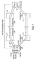
- FIG. 1 is a diagram for explaining the concept of LSP (Label Switched Path) load dispersion in MPLS adaptive traffic engineering (MATE) according to the path selection method of the invention.
- LSP Label Switched Path
- FIG. 2 is a block diagram of an ingress LSR (Label Switched Router) on an MPLS network to which the MPLS adaptive traffic engineering is applied.
- LSR Label Switched Router
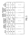
- FIG. 3 is a diagram for explaining an FEC (Forward Equivalent Class) routing table in the ingress LSR.
- FEC Forward Equivalent Class
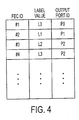
- FIG. 4 is a diagram for explaining an FEC-label mapping table in the ingress LSR.
- FIG. 5 is a diagram for explaining an FEC-label mapping table in a first preferred embodiment of the ingress LSR.
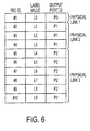
- FIG. 6 is a diagram for explaining an FEC-label mapping table in a second preferred embodiment of the ingress LSR.
- FIG. 7 is a diagram for explaining an FEC-label mapping table in a third preferred embodiment of the ingress LSR.
- FIG. 8 is a diagram for explaining an FEC-label mapping table in a fourth preferred embodiment of the ingress LSR.
- FIG. 9 is a diagram for explaining an FEC-label mapping table in the fourth preferred embodiment of the ingress LSR.
- FIG. 10 is a diagram for explaining an FEC-label mapping table in a fifth preferred embodiment of the ingress LSR.
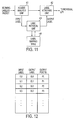
- FIG. 11 is a block diagram of an intermediate LSR on the MPLS network.
- FIG. 12 is a diagram for explaining a label mapping table in the intermediate LSR.
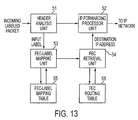
- FIG. 13 is a block diagram of an egress LSR on the MPLS network.
- FIG. 14 is a diagram for explaining the relationship between a physical link (port), LSPs, and FECS.
- FIG. 15 is a diagram for explaining packet forwarding using the FEC-Label Mapping Table of FIG. 5
- the scheme of MultiProtocol Label Switching MPLS adaptive traffic engineering (often called MATE) has the potential for effectively optimizing the use of network resources.
- MATE MultiProtocol Label Switching MPLS adaptive traffic engineering
- the traffic load on a certain path becomes too heavy, another path having a larger capacity can be selected for transmitting the traffic through the other path with the large capacity, rather than through the overloaded path.
- the traffic load can be effectively dispersed to the selected paths on the network and a long-term congestion state of the network can be avoided.
- a plurality of label switched paths within the MPLS network are predefined for transmitting the incoming traffic addressed to a same destination according to the load dispersion capability of the MPLS, it is possible to disperse the incoming traffic load to the selected ones of the plurality of paths by routing the majority part of the incoming traffic to the selected paths and the remainder to other paths of the plurality of paths.
- an incoming data packet at the ingress node of the network is grouped into a plurality of FEC (forwarding equivalent class) elements, and the plurality of FEC elements of the packet are allocated for the plurality of label switched paths on the network on an FEC-element basis.
- the grouping of the packet into the FEC elements can be arbitrarily performed, which need not be in conformity with the full IP address carried by the packet
- the grouping of the packet into the FEC elements may be performed by using either the prefix or part of the IP address of the packet or the destination IP address of the packet.
- FIG. 1 shows the concept of the label switched path (LSP) load dispersion in the MPLS adaptive traffic engineering (MATE) according to the method of the present invention.
- LSP label switched path
- MATE MPLS adaptive traffic engineering
- FIG. 14 shows the concept of the relationship between a physical link (port), label switched paths, and forward equivalent class elements (FECs).
- port physical link
- FECs forward equivalent class elements
- a traffic engineering area of a label switching network (hereinafter called MPLS network) between ingress LSR (label switching router) 10 and an egress LSR 12 is illustrated.
- MPLS network label switching network
- LSP label switched path
- LSP label switched path
- LSP 21 and the data rate of the physical link of LSP 22 may be different from each other.
- a packet-switched network such as the MPLS network, can carry out data-rate conversion. Two routers of different data rates can exchange packets, since each connects to its node at its proper data rate.
- the LSP 21 extends from the ingress LSR 10 to the egress LSR 12 through two intermediate LSRs 13 and 14, while the LSP 22 extends from the ingress LSR 10 to the egress LSR 12 through two intermediate LSRs 15 and 16.
- an incoming data packet at the ingress LSR 10 is grouped into a plurality of FEC elements, such as FEC#1, FEC#2, FEC#3 and FEC#4, and the plurality of FEC elements of the incoming packet are allocated for the label switched paths 21 and 22.
- FEC#1 and others are called FEC IDs.
- One or more FEC elements can be allocated for a single label switched path and one or more label switched paths may be allocated to a single physical link.
- a plurality of FEC IDs are predetermined for the FEC elements allocated for the label switched paths 21 and 22 at the ingress LSR 10.
- the FEC #1 and the FEC #2 are allocated for the LSP 21, and the FEC #3 and the FEC #4 are allocated for the LSP 22.
- the distribution of data elements of the incoming packet to the respective label switched paths within the MPLS network in the present embodiment is performed on an FEC-element basis.
- the MPLS network of the present embodiment to which the MPLS adaptive traffic engineering is applied is intended for speeding up data communication over an ATM network.
- a separate IP-based network, other than the ATM network is connected to the egress edge of the MPLS network of the present embodiment.
- FIG. 2 is a block diagram of the ingress LSR 10 on the MPLS network to which the MPLS adaptive traffic engineering is applied.
- the ingress LSR 10 generally comprises a header analysis unit 31, an FEC retrieval unit 32, an FEC routing table 34, an ATM cell generator unit 33, an FEC-label mapping unit 35, and an FEC-label mapping table 36.
- the first incoming data packet is received at an input terminal 30 of the header analysis unit 31.
- the header analysis unit 31 analyzes the IP packet header, which precedes the incoming data packet
- the header analysis unit 31 reads, from the header, a source IP address, a destination IP address, a source TCP/UDP port identifier, a destination TCP/UDP port identifier.
- the header analysis unit 31 supplies the read header elements to the FEC retrieval unit 32, and, in parallel to this, the header analysis unit 31 supplies the data packet to the ATM cell generator unit 33.
- the FEC retrieval unit 32 produces a specific FEC ID (and its FEC priority) from the received header elements (the source IP address, the destination IP address, the source TCP/UDP port ID, the destination TCP/UDP port ID) by retrieving the FEC routing table 34 (shown in FIG. 3) based on the received header elements.
- the specific FEC ID obtained by the FEC retrieval unit 32, is used to determine a forwarding equivalent class FEC to which the incoming data packet pertains.
- FIG. 3 shows an FEC routing table 34 in the ingress LSR of FIG. 2.
- the FEC routing table 34 is stored in a memory of the ingress LSR 10.
- the FEC routing table 34 contains a plurality of records corresponding to a plurality of predetermined FEC IDs, each record having a source IP address field, a destination IP address field, a source TCP/UDP port ID field, a destination TCP/UDP port ID field, and an FEC priority field, corresponding to one of the plurality of predetermined FEC IDs allocated for the label switched paths 21 and 22.
- the source IP address field defines an IP address of a source terminal or an IP address of an external network including the source terminal.
- the source IP address is a unique, 32-bit terminal address identifier that is expressed in dotted decimal form with four address fields, such as "10.25.1.1”.
- the source IP address is a unique network address identifier that is expressed in dotted decimal form with four address fields with a prefix, such as "10.25.2.0/24".
- the prefix "/24" in the example "10.25.2.0/24" means that only the upper 24 bits of the 32-bit identifier are valid to identify the source network address, that is, the source network IP address is "10.25.2".
- the destination IP address field defines an IP address of a destination terminal or an IP address of an external network including the destination terminal.
- the destination IP address is a unique, 32-bit terminal address identifier that is expressed in dotted decimal form with four address fields, such as "10.25.1.1".
- the destination IP address is a unique network address identifier that is expressed in dotted decimal form with four address fields with a prefix, such as "10.25.2.0/24",
- the prefix "/24" in the example "10.25.2.0/24" means that only the upper 24 bits of the 32-bit identifier are valid to identify the destination network address, that is, the destination network's IP address is "10.25.2".
- the source TCP/UDP port ID field defines a TCP (transmission control protocol) port identifier or UDP (user datagram protocol) port identifier of the source terminal.
- the source TCP/UDP port ID is obtained by reading the TCP/UDP packet header included in the IP packet.
- the source TCP/UDP port ID "20" shown in FIG. 3, means that an FTP (file transfer protocol) application as a TCP layer application, is the source of the incoming IP packet.
- the destination TCP/UDP port ID field defines a TCP port identifier or UDP port identifier of the destination terminal.
- the destination TCP/UDP port ID is obtained by reading the TCP/UDP packet header included in the IP packet.
- the FEC routing table of FIG. 3 contains both the source TCP/UDP port ID field and the destination TCP/UDP port ID field.
- the port ID designated by the client, is exchanged between the client and the server. However, it is uncertain whether the client or the server is the source terminal or the destination terminal. Hence, the FEC routing table of FIG. 3 contains both the source port ID field and the destination port ID field.
- the FEC priority field defines an FEC priority that is used to set a specific priority level for one of the plurality of predetermined FEC IDs allocated for the label switched paths 21 and 22,
- the FEC retrieval unit 32 supplies the specific FEC ID (and its FEC priority), obtained by retrieving the FEC routing table 34 based on the above packet header elements, to the FEC-label mapping unit 35.
- the FEC-label mapping unit 35 is connected to the FEC-label mapping table 36, and produces a specific label value and a specific output port ID from the received FEC ID by retrieving the FEC-label mapping table 36 (which is shown in FIG. 4) based on the FEC ID.
- the FEC-label mapping unit 35 supplies the label value and the output port ID to the ATM cell generator unit 33.
- FIG. 4 shows an FEC-label mapping table 36 in the ingress LSR of FIG. 2.
- the FEC-label mapping table 36 is stored in a memory of the ingress LSR 10.
- the FEC-label mapping table 36 contains a plurality of records corresponding to the plurality of predetermined FEC IDs, each record having a label value address field and an output port ID, corresponding to one of the plurality of predetermined FEC IDs allocated for the label switched paths.
- the predetermined FEC IDs, such as #1, #2, etc., in the FEC-label mapping table are the same as those corresponding elements in the FEC routing table of FIG. 3.
- the label value field of each record in the FEC-label mapping table of FIG. 4 defines a label value corresponding to one of the predetermined FEC IDs, such as L0, L1, etc.
- the output port ID field in the FEC-label mapping table defines an output port ID corresponding to one of the predetermined FEC IDs, such as P0, P1, etc.
- FIG. 14 shows the relationship between the output port, label switched paths, and the FECs.
- the ATM cell generator unit 33 In the ingress LSR of FIG. 2, the ATM cell generator unit 33 generates an ATM cell from the IP data packet sent by the header analysis unit 31. In parallel to this, the ATM cell generator unit 33 produces a label from the label value sent by the FEC-label mapping unit 35, and attaches the label to the header (the VPI/VCI field) of the ATM cell.
- the virtual path identifier In the header format of the ATM cell, the virtual path identifier (VPI) is 8 bits at the user-network interface and 12 bits at the network-network interface, allowing for more virtual paths to be supported within the network.
- the virtual channel identifier (VCI) is used for routing to and from the end user.
- the ATM cell generator unit 33 delivers the labeled ATM cell from its output port indicated by the output port ID (sent by the FEC-label mapping unit 35), to the individual downstream LSR on the MPLS network,
- FIG. 5 shows an FEC-label mapping table in the first preferred embodiment of the ingress LSR on the MPLS network.
- the ingress LSR 10 generally comprises the header analysis unit 31, the FEC retrieval unit 32, the FEC routing table 34, the ATM cell generator unit 33, the FEC-label mapping unit 35 and the FEC-label mapping table 36, which are essentially the same as corresponding elements in FIG. 2 except that the FEC-label mapping table 36 in the present embodiment is configured as shown in FIG. 5, and the FEC-label mapping unit 35 produces the label value and the output port ID in response to the FEC ID by retrieving the FEC-label mapping table of FIG. 5.
- the plurality of FEC elements of the incoming traffic at the ingress node of the MPLS network are equally allocated for the plurality of label switched paths (LSPs).
- LSPs label switched paths
- the number of the FEC IDs in the FEC-label mapping table 36 is 10
- the number of the output ports in the table 36 is 5.
- the number of output ports corresponds to the number of LSPs in the network by chance.
- two of the ten FEC IDs are allocated to one of the five output port IDs as shown in FIG. 5.
- the relationship between the FEC IDs, the label switched paths, and the physical link (output port) is shown in FIG. 15.
- the FEC retrieval unit 32 and the FEC-label mapping unit 35 equally allocate the plurality of FEC elements of the incoming traffic at the ingress node for the plurality of LSPs, as shown in FIG. 15.
- the ATM cell generator unit 33 delivers the labeled taaffic on the plurality of LSPs on an FEC-element basis so as to route the labeled traffic through the MPLS network to the egress node.
- the plurality of FEC elements of the incoming traffic at the ingress node are equally allocated for the label switched paths and the label switched paths are equally allocated to the physical links, and the labeled traffic is delivered on the selected paths on an FEC-element basis.
- the path selection method and apparatus of the present embodiment is effective in dispersing the traffic load to the selected paths on the network and in optimizing the use of network resources. In particular, the reversing of the sequence of data packets sent by the same terminal, at the egress node (the egress LSR 12) of the network can be effectively prevented.
- the FEC IDs are equally allocated in this embodiment that would not necessarily have to be the case.
- the delivery of the labeled traffic on the selected paths is performed at the ingress LSR 10 on an FEC-element basis.
- the delivery of the labeled traffic on the selected paths may be performed on a packet basis.
- the incoming traffic is divided into a series of packets, such packets will be delivered on different paths of the network to the egress node. In such a case, it is necessary that the egress LSR 12 reassemble the packets, received from the different paths, into the original message.
- FIG. 6 shows an FEC-label mapping table in the second preferred embodiment of the ingress LSR on the MPLS network.
- the ingress LSR 10 generally comprises the header analysis unit 31, the FEC retrieval unit 32, the FEC routing table 34, the ATM cell generator unit 33, the FEC-label mapping unit 35 and the FEC-label mapping table 36, which are essentially the same as corresponding elements in FIG. 2 except that the FEC-label mapping table 36 in the present embodiment is configured as shown in FIG. 6, and the FEC-label mapping unit 35 produces the label value and the output port ID in response to the FEC ID by retrieving the FEC-label mapping table of FIG. 6.
- the plurality of FEC elements of the incoming traffic at the ingress node of the MPLS network are allocated for the plurality of LSPs such that the respective LSPs which are allocated to physical links which have predetermined data rates and the number of FEC elements, allocated for each physical link, is proportional to the predetermined data rate of that physical link.
- the number "M" of the FEC IDs in the FEC-label mapping table 36 is 10, and the number of the output ports in the table 36 is 3.
- the number of FEC elements allocated for the LSP1 (which is indicated by "L0")
- the number of FEC elements allocated for the LSP2, LSP3, and LSP4 which is indicated by "L1-L3"
- the number of FEC elements allocated for the LSP5-LSP10 (which is indicated by "L4-L9") are determined in accordance with the following equations.
- L0 M*a/(a+b+c)
- L1-L3 M*b/(a+b+c)
- L4-L9 M*c/(a+b+c)
- the FEC#1 is allocated for the output port P0 (corresponding to the LSP1 in this example)
- the FEC#2, FEC#3 and FEC#4 are allocated for the output port P1 (corresponding to the L1-L3 in this example)
- the FEC#5-FEC#10 are allocated for the output port P2 (corresponding to the L4-L9 in this example).
- the FEC retrieval unit 32 and the FEC-label mapping unit 35 allocate the plurality of FEC elements of the incoming traffic at the ingress node for the plurality of LSPs such that the number of FEC elements allocated for each of the LSPs is proportional to the predetermined data rate of the physical link.
- the ATM cell generator unit 33 delivers the labeled traffic on the plurality of LSPs on an FEC-element basis so as to route the labeled traffic through the MPLS network to the egress node.
- the plurality of PEC elements of the incoming traffic at the ingress node are allocated for the label switched paths in the data-rate-proportional manner, and the labeled traffic is delivered on the selected paths on an PEC-element basis.
- the path selection method and apparatus of the present embodiment is effective in dispersing the traffic load to the selected paths on the network and in optimizing the use of network resources. In particular, concentration of the traffic load on a specific path of the network can be effectively avoided. This will be effective in preventing the slowness of data transmission on the communication network caused by the delay of the specific path where the traffic load is concentrated.
- FIG. 7 shows an FEC-label mapping table in the third preferred embodiment of the ingress LSR on the MPLS network.
- the ingress LSR 10 generally comprises the header analysis unit 31, the FEC retrieval unit 32, the FEC routing table 34, the ATM cell generator unit 33, the FEC-label mapping unit 35 and the FEC-label mapping table 36, which are essentially the same as corresponding elements in FIG. 2 except that the FEC-label mapping table 36 in the present embodiment is configured as shown in FIG. 7, and the FEC-label mapping unit 35 produces the label value and the output port ID in response to the FEC ID by retrieving the FEC-label mapping table of FIG. 7.
- the plurality of FEC elements of the incoming traffic at the ingress node of the MPLS network are allocated for the plurality of LSPS.
- the plurality LSPs is tied to the physical links such that the respective physical links have predetermined weight factors, and the number of FEC elements, allocated for each physical link, is proportional to the predetermined weight factor of that physical link.
- the number "M" of the FEC IDs in the FEC-label mapping table 36 is 10, and the number of the output ports in the table 36 is 3.
- the number of FEC elements allocated for the LSP1 and LSP2 (which is indicated by "L0 and L1")
- the number of FEC elements allocated for the LSP3-LSP7 which is indicated by "L2-L6”
- the number of FEC elements allocated for the LSP8-LSP10 (which is indicated by "L7-L9" are determined in accordance with the following equations.
- L0-L1 M*w1/(w1+w2+w3)
- L2-L6 M*w2/(w1+w2 +w3)
- L7-L9 M*w3/(w1+w2 +w3)
- the FEC retrieval unit 32 and the FEC-label mapping unit 35 allocate the plurality of FEC elements of the incoming traffic at the ingress node for the plurality of LSPs such that the number of FEC elements allocated for each of the LSPs is proportional to the predetermined weight factor of the physical link.
- the ATM cell generator unit 33 delivers the labeled traffic on the plurality of LSPs on an FEC-element basis so as to route the labeled traffic through the MPLS network to the egress node.
- the plurality of FEC elements of the incoming traffic at the ingress node are allocated for the plurality of label switched paths (LSPs) in the weight-factor-proportional manner, and the labeled traffic is delivered on the selected paths on an FEC-element basis.
- the path selection method and apparatus of the present embodiment is effective in dispersing the traffic load to the selected paths on the network and in optimizing the use of network resources.
- the traffic load dispersion to the selected paths can be effectively suited to the network management conditions specified by the network administrator.
- FIG. 8 shows an FEC-label mapping table in the fourth preferred embodiment of the ingress LSR before an amount of the traffic delivered on the physical link P0 having a first priority exceeds a predetermined threshold.
- FIG. 9 shows an FEC-label mapping table in the fourth preferred embodiment of the ingress LSR after the amount of the traffic delivered on the physical link P0 has exceeded the threshold.
- the ingress LSR 10 generally comprises the header analysis unit 31, the FEC retrieval unit 32, the FEC routing table 34, the ATM cell generator unit 33, the FEC-label mapping unit 35 and the FEC-label mapping table 36, which are essentially the same as corresponding elements in FIG. 2 except that the FEC-label mapping table 36 in the present embodiment is configured as shown in FIG. 8 or FIG. 9, and the FEC-label mapping unit 35 produces the label value and the output port ID in response to the FEC ID by retrieving the FEC-label mapping table of FIG. 8 or FIG. 9.
- one of a set of priorities is assigned for each of the plurality of physical links within the MPLS network.
- Any number of label switched paths may be allocated to each of the plurality of physical links such that it may be considered that the label switched paths assigned to the physical link have the priority of the physical link.
- the plurality of FEC elements of the incoming traffic at the ingress node of the MPLS network are allocated for the plurality of LSPs in order of the respective priorities of the plurality of LSPs before an amount of the traffic delivered on one of the plurality of physical links having a first priority exceeds a predetermined threshold.
- the FEC#1, FEC#2 and FEC#3 are allocated for the first-priority L0, L1 and L2corresponding to the output port P0 before the amount of the traffic delivered on the physical link having the first priority exceeds the threshold,
- the remainders of the plurality of FEC elements of the incoming traffic at the ingress node of the MPLS network are allocated to others of the plurality of physical links having a second priority lower than the first priority.
- the FEC#4 and FEC#5 are allocated for the second-priority physical link corresponding to the output port P1 after the amount of the traffic delivered on the physical link having the first priority has exceeded the threshold.
- the FEC retrieval unit 32 and the FEC-label mapping unit 35 allocate the plurality of FEC elements of the incoming traffic at the ingress node for the plurality of LSPS in order of the respective priorities of the plurality of physical link before the amount of the traffic delivered on one of the plurality of physical links having a first priority exceeds a predetermined threshold. After the amount of the traffic on the physical link has exceeded the threshold, the FEC retrieval unit 32 and the FEC-label mapping unit 35 allocate the remainders of the plurality of FEC elements of the traffic for others of the plurality of LSPs having physical links of a second priority lower than the first priority.
- the ATM cell generator unit 33 delivers the labeled traffic on the plurality of LSPs on an FEC-element basis so as to route the labeled traffic through the MPLS network to the egress node, wherein, after the amount of the traffic on the physical link has exceeded the threshold, the traffic is routed to others of the plurality of LSPs having physical links of a second priority lower than the first priority.
- an estimated amount of the traffic delivered on each of the plurality of physical links in the MPLS network can be calculated at the ingress LSR 10.
- the algorithm of the MPLS adaptive traffic engineering (MATE) proposed by the IETF (Internet Engineering Task Force) may be used.
- the scheme of the MATE has the potential for more effectively optimizing the use of network resources as compared with that in the conventional IP-based communication networks.
- the present embodiment which makes use of the scheme of the MATE, when the load of the traffic on a certain path becomes too heavy, another path having a larger capacity can be selected for transmitting the traffic through the other path with the large capacity, rather than through the overloaded path.
- the path selection method and apparatus of the present embodiment can effectively disperse the incoming traffic load to the selected paths on the network and a long-term congestion state of the network can be avoided.
- the plurality of FEC elements of the incoming traffic at the ingress node are allocated for the plurality of LSPs in order of the respective priorities of the plurality of LSPs, and the labeled traffic is delivered on the selected paths on an FEC-element basis.
- the path selection method and apparatus of the present embodiment is effective in dispersing the traffic load to the selected paths on the network and in optimizing the use of network resources. In particular, by assigning the first priority for main route paths of the network and the second priority for sub-route paths of the network, the traffic load dispersion to the selected paths can be effectively achieved.
- FIG. 10 shows an FEC-label mapping table in the fifth preferred embodiment of the ingress LSR on the MPLS network.
- the ingress LSR 10 generally comprises the header analysis unit 31, the FEC retrieval unit 32, the FEC routing table 34, the ATM cell generator unit 33, the FEC-label mapping unit 35 and the FEC-label mapping table 36, which are essentially the same as corresponding elements in FIG. 2 except that the FEC-label mapping table 36 in the present embodiment is configured as shown in FIG. 10, and the FEC-label mapping unit 35 produces the label value and the output port ID in response to the FEC ID by retrieving the FEC-label mapping table of FIG. 10.
- one of a set of priorities is assigned for each of the plurality of LSPs within the MPLS network, and a plurality of FEC priorities are allocated for the plurality of FEC elements of the incoming traffic at the ingress node.
- the correlation between the FEC IDs and the FEC priorities is provided by the FEC routing table shown in FIG, 3, and the FEC retrieval unit 32 supplies, to the FEC-label mapping unit 35, the correlated FEC priority, obtained from the specific FEC ID by retrieving the FEC routing table of FIG. 3.
- the plurality of FEC elements of the incoming traffic at the ingress node of the MPLS network are allocated for the plurality of LSPs in order of the respective priorities of the plurality of LSPs and in order of the respective FEC priorities of the plurality of FEC elements.
- a first FEC priority "0" is allocated for the LSP1 (with the first priority) corresponding to the output port "P0”
- a second FEC priority "1” is allocated for the LSP2 (with the second priority) corresponding to the output port "P1”
- a third FEC priority "2” is allocated for the LSP3 (with the third priority) corresponding to the output port "P2”
- a fourth FEC priority "3” is allocated for the LSP4 (with the fourth priority) corresponding to the output port P3
- fifth through seventh FEC priorities "5" to "7” are allocated for the LSP5 (with the low priority) corresponding to the output port P4.
- the FEC retrieval unit 32 and the FEC-label mapping unit 35 allocate the plurality of FEC elements of the incoming traffic at the ingress node for the plurality of LSPs in order of the respective priorities of the plurality of LSPs and in order of the respective FEC priorities of the plurality of FEC elements.
- the ATM cell generator unit 33 delivers the labeled traffic on the plurality of LSPs on an FEC-element basis so as to route the labeled traffic through the MPLS network to the egress node.
- the plurality of FEC elements of the incoming traffic at the ingress node are allocated for the plurality of LSPs in order of the respective priorities of the plurality of LSPS and in order of the respective FEC priorities of the plurality of FEC elements, and the labeled traffic is delivered on the selected paths on an FEC-element basis.
- the path selection method and apparatus of the present embodiment is effective in dispersing the traffic load to the selected paths on the network and in optimizing the use of network resources.
- the traffic load dispersion to the selected paths can be achieved with increased flexibility by the allocation of the path priorities and the FEC priorities specified by the network administrator.
- the application of the path selection method and apparatus of the present invention to a packet-switched network makes it possible to disperse the incoming traffic load to the selected label switched paths. Further, it is possible to more effectively optimize the use of network resources as compared with that in the conventional IP-based communication networks.
- the traffic load dispersion to the selected paths can be achieved with increased flexibility by the allocation of the path priorities and the FEC priorities specified by the network administrator.
- each intermediate LSR In each of the intermediate label switching routers (LSRs) 13 through 16 on the MPLS network, the inconung traffic at the input of each intermediate LSR is a labeled ATM cell.
- Each intermediate LSR reads an input label from the header of the labeled ATM cell, produces an output label corresponding to the input label, attaches the output label in the header of an outgoing ATM cell, and delivers the labeled ATM cell from its output port to a downstream LSR on the MPLS network.
- FIG. 11 is a block diagram of one of the intermediate LSRs 13 through 16 on the MPLS network.
- an incoming labeled ATM cell is received at a header analysis unit 41.
- the header analysis unit 41 analyzes tbe header of the ATM cell, reads, from the header, a label value (called the input label), and supplies the input label to a label retrieval unit 43.
- the label retrieval unit 43 is connected to a label mapping table 44.
- the label retrieval unit 43 produces an output label value (called the output label) and an output port ID from the received input label by retrieving the label mapping table 44 based on the input label.
- FIG. 12 shows a label mapping table 44 in the intermediate LSR of FIG. 11.
- the label mapping table 44 contains a plurality of records corresponding to a plurality of predetermined input labels, such as IL0, IL1, etc.
- Each record includes an output label field and an output port ID field, which correspond to one of the predetermined input labels.
- the output label field defines an output label or a label value corresponding to one of the predetermined input labels, such as OL0, OL1, etc.
- the output port ID field defines an output port ID corresponding to one of the predetermined input labels, such as P0, P1, etc.
- the label retrieval unit 43 supplies the output label and the output port ID, obtained from the label mapping table 44, to a label attaching unit 42.
- the label attaching unit 42 receives the ATM cell sent by the header analysis unit 41, and attaches the output label, received from the label retrieval unit 43, in the header (the VPI/VPO field) of the received ATM cell.
- the label attaching unit 42 delivers the labeled ATM cell from its output port indicated by the output port ID (sent by the label retrieval unit 43), to the individual downstream LSR on the MPLS network.
- FIG. 13 is a block diagram of the egress LSR 12 on the MPLS network.
- an incoming labeled ATM cell is received at a header analysis unit 51.
- the header analysis unit 51 analyzes the header of the ATM cell reads, from the header, a label value (called the input label), and supplies the input label to an FEC-label mapping unit 53.
- the FEC-label mapping unit 53 is connected to an FEC-label mapping table 55.
- the FEC-label mapping unit 53 produces an FEC ID (called output label) from the received input label by retrieving the FEC-label mapping table 55 based on the input label.
- the FEC-label mapping table 55 is configured in a manner that is essentially the same as the FEC-label mapping table shown in FIG. 4.
- the FEC-label mapping unit 53 supplies the FEC ID (the output label), obtained from the FEC-label mapping table 55, to an FEC retrieval unit 54.
- the FEC retrieval unit 54 is connected to an FEC routing table 56.
- the FEC retrieval unit 54 produces a destination IP address and a destination TCP/UDP port ID from the received FEC ID by retrieving the FEC routing table 56 based on the FEC ID (the output label).
- the FEC routing table 56 is configured in a manner that is essentially the same as the FEC routing table shown in FIG. 3.
- the FEC retrieval unit 54 supplies the destination IP address and the destination TCP/UDP port ID, obtained from the FEC routing table 56, to an IP forwarding processor unit 52.
- the IP forwarding processor unit 52 receives the ATM cell sent by the header analysis unit 51, and reassembles the IP data packet from the received ATM cell.
- the IP forwarding processor unit 52 attaches the destination IP address, received from the FEC retrieval unit 54, in the header of the reassembled IP data packet.
- the IP forwarding processor unit 52 delivers the labeled IP data packet from its output port indicated by the destination TCP/UDP port ID (received from the FEC retrieval unit 54) to the destination of the external IP network (indicated by the destination IP address).
- data communication in the traffic engineering area between the ingress node (the ingress LSR 10) and the egress node (the egress LSR 12) is carried out through the ATM network
- an IP packet-switched network, a frame relay network, a point-to-point link or the like may be used, instead of the ATM network, as the communication medium through which the data is transmitted.
- the ingress LSR 10 of FIG. 1 corresponds to the ingress node or the ingress-node apparatus.
- the egress LSR 12 of FIG. 1 corresponds to the egress node.
- the elements 32, 34, 35 and 36 of FIG. 2 wherein the FEC routing table 34 is configured as shown in FIG. 3 and the FEC-label mapping table 36 is configured as shown in any of FIG. 4, FIG. 5, FIG. 6, FIG. 7, FIG. 8 (or FIG. 9) and FIG. 10, correspond to the FEC allocation unit or the allocating step.
- the elements 31 and 33 of FIG. 2 correspond to the traffic delivery unit or the delivering step.
- the method for selection of paths to route the incoming traffic through the communication network is effective in dispersing the traffic load to the selected paths on the network and in optimizing the use of network resources. Reversing of a sequence of data packets sent by the same terminal, at the egress node of the network can be effectively reduced.
- the method for selection of paths to route the incoming traffic through the communication network is effective in dispersing the traffic load to the selected paths on the network and in optimizing the use of network resources, Concentration of the traffic load on a specific path of the network can be effectively reduced,
- the method for selection of paths to route the incoming traffic through the communication network is effective in dispersing the traffic load to the selected paths on the network and in optimizing the use of network resources.
- the traffic load dispersion to the selected paths can be effectively suited to the network management conditions specified by a network administrator.
- the method for selection of paths to route the incoming traffic through the communication network is effective in dispersing the traffic load to the selected paths on the network and in optimizing the use of network resources.
- the traffic load dispersion to the selected paths can be effectively achieved.
- the method for selection of paths to route the incoming traffic through the communication network is effective in dispersing the traffic load to the selected paths on the network and in optimizing the use of network resources.
- the traffic load dispersion to the selected paths can be achieved with increased flexibility by the allocation of the path priorities and the FEC priorities specified by a network administrator.
- the apparatus for selection of paths to route the incoming traffic through the communication network is effective in dispersing the traffic load to the selected paths on the network and in optimizing the use of network resources. Reversing of a sequence of data packets sent by the same terminal, at the egress node of the network can be effectively prevented.
- the apparatus for selection of paths to route the incoming traffic through the communication network is effective in dispersing the traffic load to the selected paths on the network and in optimizing the use of network resources. Concentration of the traffic load on a specific path of the network can be effectively avoided.
- the apparatus for selection of paths to route the incoming traffic through the communication network is effective in dispersing the traffic load to the selected paths on the network and in optimizing the use of network resources.
- the traffic load dispersion to the selected paths can be effectively suited to the network management conditions specified by a network administrator.
- the apparatus for selection of paths to route the incoming traffic through the communication network is effective in dispersing the traffic load to the selected paths on the network and in optimizing the use of network resources, By assigning the first priority for main route paths of the network and the second priority for sub-route paths of the network, the traffic load dispersion to the selected paths can be effectively achieved.
- the apparatus for selection of paths to route the incoming traffic through the communication network is effective in dispersing the traffic load to the selected paths on the network and in optimizing the use of network resources.
- the traffic load dispersion to the selected paths can be achieved with increased flexibility by the allocation of the path priorities and the FEC priorities specified by a network administrator.
Landscapes
- Engineering & Computer Science (AREA)
- Computer Networks & Wireless Communication (AREA)
- Signal Processing (AREA)
- Data Exchanges In Wide-Area Networks (AREA)
- Telephonic Communication Services (AREA)
Applications Claiming Priority (2)
| Application Number | Priority Date | Filing Date | Title |
|---|---|---|---|
| JP32159199A JP3781928B2 (ja) | 1999-11-11 | 1999-11-11 | 通信網のパス選択方法及びその装置 |
| JP32159199 | 1999-11-11 |
Publications (2)
| Publication Number | Publication Date |
|---|---|
| EP1100233A2 true EP1100233A2 (de) | 2001-05-16 |
| EP1100233A3 EP1100233A3 (de) | 2004-01-02 |
Family
ID=18134263
Family Applications (1)
| Application Number | Title | Priority Date | Filing Date |
|---|---|---|---|
| EP20000124252 Withdrawn EP1100233A3 (de) | 1999-11-11 | 2000-11-10 | Verfahren und Vorrichtung zum Wegeauswahl in einem Komunicationsnetz |
Country Status (3)
| Country | Link |
|---|---|
| US (1) | US6859842B1 (de) |
| EP (1) | EP1100233A3 (de) |
| JP (1) | JP3781928B2 (de) |
Cited By (8)
| Publication number | Priority date | Publication date | Assignee | Title |
|---|---|---|---|---|
| WO2003092226A1 (en) * | 2002-04-24 | 2003-11-06 | Nokia Corporation | A method and system for forwarding data units |
| WO2004006516A3 (en) * | 2002-07-04 | 2004-04-08 | Univ Cambridge Tech | Packet routing |
| EP1433287A4 (de) * | 2001-10-02 | 2006-12-06 | Fujitsu Ltd | Schutzumschaltung in einem kommunikationsnetz mit label-umschaltung |
| EP1609279A4 (de) * | 2003-04-01 | 2008-11-05 | Cisco Tech Inc | Verfahren für rekursive bgp-routenaktualisierung in mpls-netzwerken |
| EP1615391A4 (de) * | 2003-04-11 | 2010-04-07 | Fujitsu Ltd | Mobiles kommunikationssystem und datenverteilungsverfahren in diesem system |
| US7890656B2 (en) | 2003-02-13 | 2011-02-15 | Fujitsu Limited | Transmission system, delivery path controller, load information collecting device, and delivery path controlling method |
| US8325618B2 (en) | 2006-07-05 | 2012-12-04 | Synopsys, Inc. | Electronic device, system on chip and method for monitoring a data flow |
| US9461903B2 (en) | 2013-03-21 | 2016-10-04 | Fujitsu Limited | Communication device, communication system, and communication method |
Families Citing this family (60)
| Publication number | Priority date | Publication date | Assignee | Title |
|---|---|---|---|---|
| US6973102B2 (en) * | 2000-07-31 | 2005-12-06 | Telefonaktiebolaget Lm Ericsson (Publ) | Jitter reduction in differentiated services (DiffServ) networks |
| US7583796B2 (en) * | 2000-11-30 | 2009-09-01 | Fujitsu Limited | Apparatus and method for generating a data distribution route |
| US7277962B2 (en) * | 2000-12-01 | 2007-10-02 | Fujitsu Limited | Method and apparatus for packet scheduling using virtual time stamp for high capacity combined input and output queued switching system |
| JP2002359636A (ja) * | 2001-05-31 | 2002-12-13 | Nec Corp | 経路ペア設計方法、経路ペア設計装置及びプログラム |
| FR2828045B1 (fr) * | 2001-07-26 | 2003-10-03 | Cit Alcatel | Procede de selection de chemins de transmission et reseau de communication mettant en oeuvre ce procede |
| JP2003078553A (ja) * | 2001-08-31 | 2003-03-14 | Hitachi Ltd | パケット転送方法 |
| US7277393B1 (en) * | 2002-03-13 | 2007-10-02 | Packet Design, Inc. | System and method for identifying cost metrics for a network |
| US7480253B1 (en) * | 2002-05-30 | 2009-01-20 | Nortel Networks Limited | Ascertaining the availability of communications between devices |
| JP3924523B2 (ja) | 2002-10-29 | 2007-06-06 | 富士通株式会社 | 伝送装置および伝送方法 |
| US7257119B2 (en) * | 2002-12-23 | 2007-08-14 | At&T | MPLS virtual private network using dual network cores |
| JP3769544B2 (ja) | 2003-01-31 | 2006-04-26 | 富士通株式会社 | 伝送帯域制御装置 |
| US7397795B2 (en) * | 2003-02-24 | 2008-07-08 | Intel California | Method and system for label-based packet forwarding among multiple forwarding elements |
| US7006499B2 (en) * | 2003-04-28 | 2006-02-28 | Alcatel Ip Networks, Inc. | Source identifier for MAC address learning |
| US20040223494A1 (en) * | 2003-05-06 | 2004-11-11 | Lg Electronics Inc. | Traffic forwarding method in ATM based MPLS system and apparatus thereof |
| US8554860B1 (en) * | 2003-09-05 | 2013-10-08 | Sprint Communications Company L.P. | Traffic segmentation |
| WO2005067227A1 (ja) * | 2004-01-09 | 2005-07-21 | Nec Corporation | 負荷分散方法、ノード及び制御プログラム |
| JP2005260321A (ja) * | 2004-03-09 | 2005-09-22 | Nec Corp | ラベルパスネットワークの迂回制御方式 |
| US7643425B2 (en) * | 2004-07-23 | 2010-01-05 | Ericsson Ab | LSP path selection |
| JP4567391B2 (ja) * | 2004-07-26 | 2010-10-20 | パナソニック株式会社 | モジュール間通信装置および方法 |
| CN1327673C (zh) * | 2005-01-29 | 2007-07-18 | 华为技术有限公司 | 一种多协议标签交换网络的数据传输方法及系统 |
| US7889711B1 (en) | 2005-07-29 | 2011-02-15 | Juniper Networks, Inc. | Filtering traffic based on associated forwarding equivalence classes |
| US8171238B1 (en) | 2007-07-05 | 2012-05-01 | Silver Peak Systems, Inc. | Identification of data stored in memory |
| US8392684B2 (en) | 2005-08-12 | 2013-03-05 | Silver Peak Systems, Inc. | Data encryption in a network memory architecture for providing data based on local accessibility |
| US8370583B2 (en) * | 2005-08-12 | 2013-02-05 | Silver Peak Systems, Inc. | Network memory architecture for providing data based on local accessibility |
| US8095774B1 (en) | 2007-07-05 | 2012-01-10 | Silver Peak Systems, Inc. | Pre-fetching data into a memory |
| US8489562B1 (en) | 2007-11-30 | 2013-07-16 | Silver Peak Systems, Inc. | Deferred data storage |
| US8811431B2 (en) | 2008-11-20 | 2014-08-19 | Silver Peak Systems, Inc. | Systems and methods for compressing packet data |
| US8929402B1 (en) | 2005-09-29 | 2015-01-06 | Silver Peak Systems, Inc. | Systems and methods for compressing packet data by predicting subsequent data |
| US20070153813A1 (en) * | 2005-12-29 | 2007-07-05 | Level 3 Communications, Inc. | Traffic distribution in a communications network |
| US7643499B2 (en) * | 2006-06-30 | 2010-01-05 | Alcatel Lucent | Extending IP/MPLS services reachability over ATM backbone networks |
| US8885632B2 (en) | 2006-08-02 | 2014-11-11 | Silver Peak Systems, Inc. | Communications scheduler |
| US8755381B2 (en) | 2006-08-02 | 2014-06-17 | Silver Peak Systems, Inc. | Data matching using flow based packet data storage |
| JP4734617B2 (ja) * | 2006-11-24 | 2011-07-27 | Kddi株式会社 | パス選択装置およびパス選択方法、通信中継装置 |
| WO2008100496A1 (en) * | 2007-02-13 | 2008-08-21 | Gainspan Corporation | Preferential transmission of non-coded data over forward error correction coded data for efficient power management of a remote device |
| US8307115B1 (en) | 2007-11-30 | 2012-11-06 | Silver Peak Systems, Inc. | Network memory mirroring |
| US8477600B2 (en) * | 2008-01-18 | 2013-07-02 | Futurewei Technologies, Inc. | Composite transport functions |
| US8442052B1 (en) | 2008-02-20 | 2013-05-14 | Silver Peak Systems, Inc. | Forward packet recovery |
| US9717021B2 (en) | 2008-07-03 | 2017-07-25 | Silver Peak Systems, Inc. | Virtual network overlay |
| US10164861B2 (en) | 2015-12-28 | 2018-12-25 | Silver Peak Systems, Inc. | Dynamic monitoring and visualization for network health characteristics |
| US10805840B2 (en) | 2008-07-03 | 2020-10-13 | Silver Peak Systems, Inc. | Data transmission via a virtual wide area network overlay |
| US8743683B1 (en) | 2008-07-03 | 2014-06-03 | Silver Peak Systems, Inc. | Quality of service using multiple flows |
| US7948986B1 (en) * | 2009-02-02 | 2011-05-24 | Juniper Networks, Inc. | Applying services within MPLS networks |
| US8948174B2 (en) | 2011-06-29 | 2015-02-03 | Juniper Networks, Inc. | Variable-based forwarding path construction for packet processing within a network device |
| US9130991B2 (en) | 2011-10-14 | 2015-09-08 | Silver Peak Systems, Inc. | Processing data packets in performance enhancing proxy (PEP) environment |
| US9626224B2 (en) | 2011-11-03 | 2017-04-18 | Silver Peak Systems, Inc. | Optimizing available computing resources within a virtual environment |
| US20150327113A1 (en) * | 2012-02-22 | 2015-11-12 | Nec Corporation | Communication device and traffic control method |
| JP5451861B1 (ja) * | 2012-11-09 | 2014-03-26 | 日本電信電話株式会社 | 光パケットスイッチネットワークにおける優先経路の設定方法及び設定装置 |
| US9331946B2 (en) * | 2013-01-08 | 2016-05-03 | Hitachi, Ltd. | Method and apparatus to distribute data center network traffic |
| JP6197358B2 (ja) * | 2013-05-14 | 2017-09-20 | 富士通株式会社 | 基地局装置、基地局装置におけるデータ送信方法、及び無線通信システム |
| US9948496B1 (en) | 2014-07-30 | 2018-04-17 | Silver Peak Systems, Inc. | Determining a transit appliance for data traffic to a software service |
| US9875344B1 (en) | 2014-09-05 | 2018-01-23 | Silver Peak Systems, Inc. | Dynamic monitoring and authorization of an optimization device |
| US10432484B2 (en) | 2016-06-13 | 2019-10-01 | Silver Peak Systems, Inc. | Aggregating select network traffic statistics |
| US9967056B1 (en) | 2016-08-19 | 2018-05-08 | Silver Peak Systems, Inc. | Forward packet recovery with constrained overhead |
| US11044202B2 (en) | 2017-02-06 | 2021-06-22 | Silver Peak Systems, Inc. | Multi-level learning for predicting and classifying traffic flows from first packet data |
| US10257082B2 (en) | 2017-02-06 | 2019-04-09 | Silver Peak Systems, Inc. | Multi-level learning for classifying traffic flows |
| US10771394B2 (en) | 2017-02-06 | 2020-09-08 | Silver Peak Systems, Inc. | Multi-level learning for classifying traffic flows on a first packet from DNS data |
| US10892978B2 (en) | 2017-02-06 | 2021-01-12 | Silver Peak Systems, Inc. | Multi-level learning for classifying traffic flows from first packet data |
| US11212210B2 (en) | 2017-09-21 | 2021-12-28 | Silver Peak Systems, Inc. | Selective route exporting using source type |
| US10637721B2 (en) | 2018-03-12 | 2020-04-28 | Silver Peak Systems, Inc. | Detecting path break conditions while minimizing network overhead |
| US12034570B2 (en) | 2022-03-14 | 2024-07-09 | T-Mobile Usa, Inc. | Multi-element routing system for mobile communications |
Family Cites Families (4)
| Publication number | Priority date | Publication date | Assignee | Title |
|---|---|---|---|---|
| JPH066381A (ja) | 1992-06-19 | 1994-01-14 | Fujitsu Ltd | 通信路帯域可変設定方式 |
| JPH07115434A (ja) | 1993-10-19 | 1995-05-02 | Oki Electric Ind Co Ltd | ルーチング装置 |
| EP0753979A1 (de) | 1995-07-13 | 1997-01-15 | International Business Machines Corporation | Methode und System für Wegesuche in einem schnellen Paketvermittlungsnetzwerk |
| US6584071B1 (en) * | 1999-08-03 | 2003-06-24 | Lucent Technologies Inc. | Routing with service level guarantees between ingress-egress points in a packet network |
-
1999
- 1999-11-11 JP JP32159199A patent/JP3781928B2/ja not_active Expired - Fee Related
-
2000
- 2000-11-09 US US09/709,230 patent/US6859842B1/en not_active Expired - Lifetime
- 2000-11-10 EP EP20000124252 patent/EP1100233A3/de not_active Withdrawn
Cited By (13)
| Publication number | Priority date | Publication date | Assignee | Title |
|---|---|---|---|---|
| EP1433287A4 (de) * | 2001-10-02 | 2006-12-06 | Fujitsu Ltd | Schutzumschaltung in einem kommunikationsnetz mit label-umschaltung |
| WO2003092226A1 (en) * | 2002-04-24 | 2003-11-06 | Nokia Corporation | A method and system for forwarding data units |
| WO2004006516A3 (en) * | 2002-07-04 | 2004-04-08 | Univ Cambridge Tech | Packet routing |
| US7890656B2 (en) | 2003-02-13 | 2011-02-15 | Fujitsu Limited | Transmission system, delivery path controller, load information collecting device, and delivery path controlling method |
| EP1609279A4 (de) * | 2003-04-01 | 2008-11-05 | Cisco Tech Inc | Verfahren für rekursive bgp-routenaktualisierung in mpls-netzwerken |
| US7567569B2 (en) | 2003-04-01 | 2009-07-28 | Cisco Technology, Inc. | Method for recursive BGP route updates in MPLS networks |
| EP2043399A3 (de) * | 2003-04-11 | 2010-04-07 | Fujitsu Limited | Mobiles Kommunikationssystem und Verfahren zur Datenausbreitung in diesem System |
| EP1615391A4 (de) * | 2003-04-11 | 2010-04-07 | Fujitsu Ltd | Mobiles kommunikationssystem und datenverteilungsverfahren in diesem system |
| EP2367377A1 (de) * | 2003-04-11 | 2011-09-21 | Fujitsu Limited | Mobiles kommunikationssystem und datenverteilungsverfahren in diesem system |
| EP2515576A1 (de) * | 2003-04-11 | 2012-10-24 | Fujitsu Limited | Mobiles Kommunikationssystem und Verfahren zur Datendispersion in diesem System |
| US8526361B2 (en) | 2003-04-11 | 2013-09-03 | Fujitsu Limited | Mobile communication system and method of data dispersion in said system |
| US8325618B2 (en) | 2006-07-05 | 2012-12-04 | Synopsys, Inc. | Electronic device, system on chip and method for monitoring a data flow |
| US9461903B2 (en) | 2013-03-21 | 2016-10-04 | Fujitsu Limited | Communication device, communication system, and communication method |
Also Published As
| Publication number | Publication date |
|---|---|
| JP3781928B2 (ja) | 2006-06-07 |
| US6859842B1 (en) | 2005-02-22 |
| JP2001144804A (ja) | 2001-05-25 |
| EP1100233A3 (de) | 2004-01-02 |
Similar Documents
| Publication | Publication Date | Title |
|---|---|---|
| US6859842B1 (en) | Method and apparatus for selection of paths on a communication network | |
| US7889661B2 (en) | Constrained multipath routing method in a multi-protocol label switching (MPLS) network | |
| US7453884B2 (en) | Apparatus and method for scalable and dynamic traffic engineering in a data communication network | |
| US6148000A (en) | Merging of data cells at network nodes | |
| Xiao et al. | Internet QoS: A big picture | |
| US7012919B1 (en) | Micro-flow label switching | |
| US7079493B2 (en) | Device and method for collecting traffic information | |
| US7065089B2 (en) | Method and system for mediating traffic between an asynchronous transfer mode (ATM) network and an adjacent network | |
| EP0869695A1 (de) | System zum Routing von paketvermitteltem Verkehr | |
| JP2002530939A (ja) | インターネット・プロトコル・コネクション指向サービスの管理方法 | |
| Sun et al. | Quality of service using traffic engineering over MPLS: An analysis | |
| Xiao | Providing quality of service in the Internet | |
| Le Faucheur | IETF multiprotocol label switching (MPLS) architecture | |
| US20050238001A1 (en) | Virtual ethernet mac switching | |
| US20060045014A1 (en) | Method for partially maintaining packet sequences in connectionless packet switching with alternative routing | |
| Filsfils et al. | Engineering a multiservice IP backbone to support tight SLAs | |
| Hunt | Evolving technologies for new internet applications | |
| Akar et al. | A reordering-free multipath traffic engineering architecture for Diffserv-MPLS networks | |
| Balakrishnan et al. | QoS and differentiated services in a multiservice network environment | |
| KR100377202B1 (ko) | 통신시스템에서 트래픽 엔지니어링을 위한 최적 경로 설정방법 | |
| AU781148B2 (en) | Method for evaluating routes in a communications network | |
| Zhang et al. | QoS Routing for DiffServ Networks: Issues and Solutions | |
| Semeria et al. | Multiprotocol label switching | |
| JP4844607B2 (ja) | 帯域監視方法および装置 | |
| Sánchez-López et al. | Providing QoS in MPLS-ATM integrated environment |
Legal Events
| Date | Code | Title | Description |
|---|---|---|---|
| PUAI | Public reference made under article 153(3) epc to a published international application that has entered the european phase |
Free format text: ORIGINAL CODE: 0009012 |
|
| AK | Designated contracting states |
Kind code of ref document: A2 Designated state(s): AT BE CH CY DE DK ES FI FR GB GR IE IT LI LU MC NL PT SE TR |
|
| AX | Request for extension of the european patent |
Free format text: AL;LT;LV;MK;RO;SI |
|
| PUAL | Search report despatched |
Free format text: ORIGINAL CODE: 0009013 |
|
| AK | Designated contracting states |
Kind code of ref document: A3 Designated state(s): AT BE CH CY DE DK ES FI FR GB GR IE IT LI LU MC NL PT SE TR |
|
| AX | Request for extension of the european patent |
Extension state: AL LT LV MK RO SI |
|
| 17P | Request for examination filed |
Effective date: 20040204 |
|
| 17Q | First examination report despatched |
Effective date: 20040227 |
|
| AKX | Designation fees paid |
Designated state(s): DE FR GB |
|
| 17Q | First examination report despatched |
Effective date: 20040227 |
|
| STAA | Information on the status of an ep patent application or granted ep patent |
Free format text: STATUS: THE APPLICATION IS DEEMED TO BE WITHDRAWN |
|
| 18D | Application deemed to be withdrawn |
Effective date: 20070815 |