EP1101016B1 - Procede de commande de la position de fin de course d'une valve de commutation des gaz actionnee par un actuateur electromagnetique dans un moteur a combustion interne - Google Patents
Procede de commande de la position de fin de course d'une valve de commutation des gaz actionnee par un actuateur electromagnetique dans un moteur a combustion interne Download PDFInfo
- Publication number
- EP1101016B1 EP1101016B1 EP00945689A EP00945689A EP1101016B1 EP 1101016 B1 EP1101016 B1 EP 1101016B1 EP 00945689 A EP00945689 A EP 00945689A EP 00945689 A EP00945689 A EP 00945689A EP 1101016 B1 EP1101016 B1 EP 1101016B1
- Authority
- EP
- European Patent Office
- Prior art keywords
- armature
- gas exchange
- exchange valve
- anchor
- electromagnets
- Prior art date
- Legal status (The legal status is an assumption and is not a legal conclusion. Google has not performed a legal analysis and makes no representation as to the accuracy of the status listed.)
- Expired - Lifetime
Links
Images


Classifications
-
- F—MECHANICAL ENGINEERING; LIGHTING; HEATING; WEAPONS; BLASTING
- F01—MACHINES OR ENGINES IN GENERAL; ENGINE PLANTS IN GENERAL; STEAM ENGINES
- F01L—CYCLICALLY OPERATING VALVES FOR MACHINES OR ENGINES
- F01L9/00—Valve-gear or valve arrangements actuated non-mechanically
- F01L9/20—Valve-gear or valve arrangements actuated non-mechanically by electric means
-
- F—MECHANICAL ENGINEERING; LIGHTING; HEATING; WEAPONS; BLASTING
- F01—MACHINES OR ENGINES IN GENERAL; ENGINE PLANTS IN GENERAL; STEAM ENGINES
- F01L—CYCLICALLY OPERATING VALVES FOR MACHINES OR ENGINES
- F01L9/00—Valve-gear or valve arrangements actuated non-mechanically
- F01L9/40—Methods of operation thereof; Control of valve actuation, e.g. duration or lift
- F01L2009/4086—Soft landing, e.g. applying braking current; Levitation of armature close to core surface
-
- F—MECHANICAL ENGINEERING; LIGHTING; HEATING; WEAPONS; BLASTING
- F01—MACHINES OR ENGINES IN GENERAL; ENGINE PLANTS IN GENERAL; STEAM ENGINES
- F01L—CYCLICALLY OPERATING VALVES FOR MACHINES OR ENGINES
- F01L9/00—Valve-gear or valve arrangements actuated non-mechanically
- F01L9/40—Methods of operation thereof; Control of valve actuation, e.g. duration or lift
- F01L2009/4098—Methods of operation thereof; Control of valve actuation, e.g. duration or lift relating to gap between armature shaft and valve stem end
Definitions
- An electromagnetic actuator for actuating a gas exchange valve on a piston internal combustion engine consists in essentially of two spaced apart Electromagnets, the pole faces of which face each other and between which a gas exchange valve to be actuated acting anchor against the force of at least one return spring between an open position and a closed position for the gas exchange valve to be moved back and forth is.
- One of the electromagnets serves as Closing magnet through which the gas exchange valve counteracts the force the opening spring is held in the closed position during the other electromagnet serves as an opening magnet, through which the Gas exchange valve via the armature against the force of the assigned Closing spring is held in the open position.
- the arrangement is such that the Anchor itself in a middle position between the two pole faces located. With alternating energization of the two The armature then comes against the electromagnet Force of a return spring on the pole face of the current supplied and thus catching electromagnets to the system. Becomes the holding current is switched off at the respective holding electromagnet, then the armature is driven by the force of the return spring accelerated towards the other electromagnet, the one corresponding during the anchor movement high catch current is applied so that after overshoot about the middle position of the armature by the magnetic force against the force of the electromagnet which is now catching Return spring comes to rest.
- the electromagnetic actuator is activated in Dependence on the operating data available to the engine control the piston internal combustion engine, essentially the Load request and speed.
- the gas exchange valve is located for example in its closed position, d. H. the The armature rests on the closing magnet, so it is activated essentially time-dependent, d. H. via the engine control taking into account the crankshaft position and the parameters from the load specification, which in each case the opening or Set the closing time for the gas exchange valve.
- the time interval can be over previous ones empirical data or theoretical data can be determined.
- the catching current If the catching current is switched on, it increases with increasing Approach of the anchor to the pole face of the catching Electromagnets with constant current supply the magnetic force progressively while the force acting in the opposite direction the return spring only rises linearly. This leads to the anchor in the final phase shortly before hitting the pole face of the catching electromagnet with increasing Acceleration moves, causing a hard impact the anchor comes on the pole face, which in many ways is disadvantageous, for example, by body and airborne sound excitation and the resulting noise. Around One tries to avoid this by means of a corresponding regulation the catching current shortly before the anchor hits the To reduce the pole area of the respective capturing electromagnet, whereby the approach of the armature is detected by a sensor system becomes.
- This Approach values can then be controlled via the motor control or via a separate current control for the actuator be used to reduce the current so that the anchor at a speed just slightly above "zero" on the pole face, i.e. hits gently so that the person in question Electromagnet then only with the low holding current is to be applied (see DE-A-197 23 405).
- the invention is based on the object of a method to create a much more accurate control of a electromagnetic actuator enables and noise avoids.
- This object is achieved according to the invention by a method to control an electromagnetic actuator for actuating a gas exchange valve on a piston internal combustion engine, the two spaced apart Has electromagnets, between which one on the gas exchange valve acting anchor against the force of at least a return spring between the pole faces of the two electromagnets with a predetermined stroke between open position and closed position of the gas exchange valve movable back and forth is guided here, the electromagnets via a control alternately with a catch current and the stroke of the armature as it moves from a sensor system one pole face to the other pole face is detected, and depending on the actual values of the armature stroke the catching electromagnet via the controller regarding the current in the form of a pilot control is controlled so that the armature in a target window Predeterminable distance range to the pole face of the trap Electromagnets move at a "zero" speed moves and that at the end of the stroke the holding current of the catching electromagnet is guided so that the armature is kept floating with a small distance to the pole
- actual values of the armature stroke contains in addition to the time switching off the holding current at least the detection the respective end position of the anchor and, if necessary, the acquisition its speed and acceleration.
- the sensor system can measure the speed either captured directly or from which itself the derivation of the path resulting in the position detection of time as well as acceleration are derived.
- anchor stroke in the sense of the invention The process is defined by the path of the gas exchange valve between its closed position and its open position, and without the anchor moving due to a valve clearance of its support on the shaft of the gas exchange valve releases.
- the distance between the two pole faces is about that Dimension of a valve clearance larger than the armature stroke.
- the actual values of the armature stroke at least in of the respective end position there is the possibility towards the end of the armature stroke the catching electromagnet with regard to the current so that the anchor in a predefinable distance range, a so-called “target window", itself at a speed going towards “zero” and an acceleration going towards “zero” and at the end of the anchor stroke, the holding current is guided is that the armature is floating without contact with the pole face is held.
- the possibility of an individual Adjustment of the current supply to the electromagnet in question considering the while moving on given external influences affecting the anchor. in this connection it is sufficient if these specifications regarding speed and acceleration in a predeterminable large distance range to the pole face.
- the movement phase that begins when the target window is reached is characterized by a slow anchor speed and a high force effect of the catching magnet.
- a slow anchor speed and a high force effect of the catching magnet In order to is in this phase about energizing the catching magnet controlled guidance of the anchor against the force of the Return spring possible until the end of the armature stroke, so that holding the anchor at a preferably small distance to the pole face is ensured.
- the energization of the electromagnets can be controlled of the voltage applied to the catching magnet become.
- voltage regulation instead of current regulation the necessary control interventions can be very effect much more precisely and quickly, even after switching off the voltage the current drops relatively slowly and accordingly when a voltage is applied the current increases relatively slowly accordingly.
- the voltage and power supply is expedient to the vehicle electrical system taken from the piston internal combustion engine.
- Fig. 1 is an electromagnetic actuator 1 for actuation of a gas exchange valve 2, which is essentially from a closing magnet 3 and an opening magnet 4 exists, which are spaced from each other and between an anchor 5 against the force of return springs, namely an opening spring 7 and a closing spring 8 and is movably guided forth.
- the closing spring 8 acts directly via one the shaft 2.1 of the gas exchange valve 2 connected spring plate 2.2 a.
- the guide rod 11 of the armature 5, which is in itself can be divided, is separated from the shaft 2.1.
- valve clearance VS there is a so-called valve clearance VS.
- the opening spring 7 is in turn supported on a spring plate 11.1 on the guide rod 11, so that under the action of opening spring 7 in the position shown, the guide rod 11 on the Shaft 2.1 of the gas exchange valve 2 is pressed. If there is a valve clearance compensation corresponds to the distance VS the intended hover area.
- the closing spring 8 and the opening spring 7 are usually like this designed that at rest, d. H. with de-energized Electromagnet of the armature 5 is in the middle position. From this middle position, anchor 5 must then be included in the start his gas exchange valve 2 can be swung.
- the energization of the electromagnets 3 and 4 of the actuator 1 takes place via a current controller 9.1 assigned to it by an electronic engine control 9 according to the given Control programs and depending on the engine control supplied operating data, such as speed, temperature etc. controlled. While it's basically possible one for all actuators on a piston internal combustion engine Providing central current regulator is it for the process expedient according to the invention if each actuator has its own Current controller is associated with a central power supply 9.2 is connected and that of the engine control 9 is controlled.
- a sensor 10 is assigned to the actuator 1, which detects the which enables anchor functions.
- Sensor 10 is here shown schematically.
- the stroke of the armature 5 is detected, so that the respective armature position the motor controller 9 and / or the current regulator 9.1 can be transmitted.
- the engine control 9 or the Current controller 9.1 can then use appropriate arithmetic operations possibly also the anchor speed and / or the acceleration be determined so that depending on the anchor position and / or depending on the anchor speed and / or the acceleration the energization of the two Electromagnets 3, 4 in the catching phase and in the holding phase can be controlled.
- the sensor 10 does not necessarily have to, as shown, one associated with the armature 5 connected push rod 11.1 his. It is also possible to have a suitably trained Sensor to assign the armature 5 laterally or also corresponding sensors in the area of the pole face of the respective Arrange electromagnets.
- the current controller 9.1 also has corresponding means for detection of current and voltage for the respective electromagnet 3 and 4 and for changing the current profile and of the voltage curve.
- the actuator 1 of the Gas exchange valve 2 can be controlled fully variably, for example regarding the start and end of opening hours. Also control with regard to the height of the opening stroke or also the number of opening strokes during the Closing times are controllable. Even small opening strokes from the closed state by "slowly floating" detachment and “Slowly floating" placement of the valve is possible.
- the current supply is in accordance with the method according to the invention of the closing magnet 3 via the current regulator 9.1 so led that the armature with a small distance to the pole face of the Closing magnet 3 is held with ideal current supply that the armature 5 is still in contact with its guide rod 11 stands with the stem 2.1 of the gas exchange valve.
- the through the Holding current generated magnetic force of the closing magnet 3 is ideally guided so that the force in the contact surface between the guide rod 11 and the valve stem 2.1 goes to "zero" and thus the gas exchange valve 2 the full force of the closing spring 8 pressed onto its valve seat becomes.
- the remaining gap between the pole face of the closing magnet 3 and the facing surface of the armature 5 corresponds approximately to the valve clearance VS.
- FIG. 1 in relation to the embodiment.
- FIG. 1 with line 12 schematically the course of the armature movement represented over a full movement cycle.
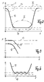
- Fig. 2 with curve 12 is the course of the stroke of the armature 5 depending on the time for a full valve clearance shown, starting with that shown in Fig. 1 Closed position over the open position back in the full closed position.
- Line 13 marks the position of the pole face of the closing magnet 3 and line 14 indicates the position of the pole face of the opening magnet 4.
- the holding current of the two electromagnets 3 and 4 so is that the anchor 5 floating in front of the respective Pole surface is held.
- Fig. 3 is the one marked in Fig. 2 with I on a larger scale Area shown.
- Line 13 shows again the position of the pole face of the closing magnet.
- the curve branch 12 shows the course of the movement from the floating stop position of the armature after the stop current has been switched off. From the history it can be seen that when the Holding current the anchor movement without sticking time and without superimposed vibrations.
- the area II in FIG. 4 is then shown on a larger scale in FIG. 2, namely the movement of the suspended Anchor in the open position.
- variable frequency and variable clock ratio swings as a result of the pulsating holding magnet force acting on the armature 5 also the gas exchange valve to a small extent, whereby via the spring force, the guide rod 11 firmly at the free end of the valve stem 2.1. This slight back and forth movement the valve in its open position is for the flow processes irrelevant.
- the armature 5 first moves under the action of force the closing spring 8 again in the direction of the pole face of the Closing magnet 3.
- the catching closing magnet then becomes the predetermined operating mode 3 energized accordingly to the after exceeding the middle position by a corresponding magnetic force counteracting force of the opening spring 7 to overcome.
- the movement is guided so that after an initial Acceleration via an appropriate energization of the catching locking magnet 3 the speed and also the Acceleration depending on that detected by the sensor 10 Anchor position becomes "zero", so that the anchor 5th again floating at a distance from the pole face of the closing magnet 3 is held.
- Line 16 in FIG. 5 shows the course of the armature stroke up to to put the gas exchange valve 2 on its valve seat (Point 17).
- Line 19 in FIG. 7 shows the course of the stroke when it is switched off the holding current, both for one on the pole face of the armature holding the electromagnet like also for one at a distance from the pole face of the holding electromagnet floating anchor applies.
- the holding current of the respective holding electromagnet only switched off briefly or lowered to accelerate bring about, then to a level below the level of equilibrium between spring force and magnetic force raised to dampen movement, then the anchor can move out of its floating end position practically vibration-free in the Middle position can be returned, as with line 20 is shown.
- Recalibration of the signal from sensor 10 can be carried out by a one-time absolute assignment of the valve clearance measurement, for example as a function of temperature. This Value is then used to measure the relative stroke, based on the contact point between valve and armature, in to provide an absolute framework.
- a sensor calibration due to the holding current level in the Levitation can be carried out as this current level essentially a function of the distance between the anchor and the pole face is in the floating position.
Landscapes
- Engineering & Computer Science (AREA)
- Mechanical Engineering (AREA)
- General Engineering & Computer Science (AREA)
- Valve Device For Special Equipments (AREA)
- Output Control And Ontrol Of Special Type Engine (AREA)
- Electrical Control Of Air Or Fuel Supplied To Internal-Combustion Engine (AREA)
- Magnetically Actuated Valves (AREA)
Claims (3)
- Procédé de commande d'un dispositif d'actionnement électromagnétique pour actionner une valve de communication des gaz dans un moteur à combustion interne, présentant deux électro-aimants disposés à distance l'un de l'autre, entre lesquels un induit agissant sur la valve de commutation de gaz contre la force d'au moins un ressort de rappel est déplacé respectivement entre les surfaces polaires des deux électro-aimants selon une course prédéterminée entre la position d'ouverture et la position de fermeture de la valve de communication des gaz, les électro-aimants étant alternativement alimentés par un courant d'interception par l'intermédiaire d'une commande, et la course de l'induit, lors de son mouvement depuis l'une des surfaces polaires vers l'autre surface polaire, étant détectée à l'aide d'un capteur et, en fonction des valeurs réelles détectées de la course de l'induit, l'électro-aimant interceptant étant commandé par la commande au niveau de l'alimentation sous la forme d'une commande pilote, de telle sorte que l'induit, dans une plage de distance par rapport à la surface polaire pouvant être définie comme fenêtre cible de l'électro-aimant interceptant respectif, se déplace à une vitesse proche de « zéro », et qu'à la fin de la course l'alimentation de maintien de l'électro-aimant interceptant soit telle que l'induit est maintenu flottant avec une faible distance par rapport à la surface polaire.
- Procédé selon la revendication 1, caractérisé en ce que la grandeur de l'alimentation de maintien entre respectivement un niveau de courant de maintien supérieur et un niveau de courant de maintien inférieur est prévue telle que le mouvement de course pulsé en résultant se situe dans la plage d'un jeu de valve donné.
- Procédé selon la revendication 1 ou 2, caractérisé en ce que lors de l'arrêt du moteur à combustion interne, la grandeur de l'alimentation de maintien pour détacher l'induit est abaissée pendant un court instant puis immédiatement rétablie à un niveau situé sensiblement en dessous de la grandeur de courant nécessaire pour l'équilibre de forces entre la force élastique et la force magnétique pour obtenir ainsi une dérive de l'induit jusque dans la position centrale de l'induit entre les surfaces polaires définie par la conception du ressort de rappel.
Applications Claiming Priority (5)
| Application Number | Priority Date | Filing Date | Title |
|---|---|---|---|
| DE19924374 | 1999-05-27 | ||
| DE19924374 | 1999-05-27 | ||
| DE10019739 | 2000-04-20 | ||
| DE10019739A DE10019739A1 (de) | 1999-05-27 | 2000-04-20 | Verfahren zur Endlagenansteuerung eines durch einen elektromagnetischen Aktuator betätigten Gaswechselventils an einer Kolbenbrennkraftmaschine |
| PCT/EP2000/004772 WO2000073635A1 (fr) | 1999-05-27 | 2000-05-25 | Procede de commande de la position de fin de course d'une valve de commutation des gaz actionnee par un actuateur electromagnetique dans un moteur a combustion interne |
Publications (2)
| Publication Number | Publication Date |
|---|---|
| EP1101016A1 EP1101016A1 (fr) | 2001-05-23 |
| EP1101016B1 true EP1101016B1 (fr) | 2002-09-18 |
Family
ID=26005409
Family Applications (1)
| Application Number | Title | Priority Date | Filing Date |
|---|---|---|---|
| EP00945689A Expired - Lifetime EP1101016B1 (fr) | 1999-05-27 | 2000-05-25 | Procede de commande de la position de fin de course d'une valve de commutation des gaz actionnee par un actuateur electromagnetique dans un moteur a combustion interne |
Country Status (5)
| Country | Link |
|---|---|
| US (1) | US6427651B1 (fr) |
| EP (1) | EP1101016B1 (fr) |
| JP (1) | JP2003500601A (fr) |
| AT (1) | ATE224505T1 (fr) |
| WO (1) | WO2000073635A1 (fr) |
Cited By (1)
| Publication number | Priority date | Publication date | Assignee | Title |
|---|---|---|---|---|
| US7089895B2 (en) | 2005-01-13 | 2006-08-15 | Motorola, Inc. | Valve operation in an internal combustion engine |
Families Citing this family (12)
| Publication number | Priority date | Publication date | Assignee | Title |
|---|---|---|---|---|
| JP2002231530A (ja) * | 2001-02-07 | 2002-08-16 | Honda Motor Co Ltd | 電磁アクチュエータ制御装置 |
| US6644253B2 (en) * | 2001-12-11 | 2003-11-11 | Visteon Global Technologies, Inc. | Method of controlling an electromagnetic valve actuator |
| JP4055443B2 (ja) * | 2002-03-11 | 2008-03-05 | トヨタ自動車株式会社 | 電磁駆動弁制御装置 |
| FR2841593B1 (fr) * | 2002-06-28 | 2006-09-22 | Procede de commande de soupapes par multiactionnement | |
| DE10300504A1 (de) * | 2003-01-08 | 2004-07-22 | Trw Deutschland Gmbh | Verfahren zum Herstellen eines Aktuators, insbesondere eines Aktuators eines nockenwellenlos angetriebenen Hubventils einer Brennkraftmaschine, sowie Aktuator |
| FR2851292B1 (fr) * | 2003-02-18 | 2007-02-23 | Peugeot Citroen Automobiles Sa | Actionneur electromecanique de soupape pour moteur a combustion interne et moteur a combustion interne muni d'un tel ationneur |
| DE10321036A1 (de) * | 2003-05-10 | 2004-11-25 | Bayerische Motoren Werke Ag | Elektrischer Ventiltrieb mit Kurzschlussring |
| US7165529B2 (en) * | 2004-12-02 | 2007-01-23 | Ford Global Technologies, Llc | Method to control electromechanical valves in a DISI engine |
| JP4577171B2 (ja) * | 2005-09-22 | 2010-11-10 | トヨタ自動車株式会社 | スライディングモード制御装置 |
| US7415950B2 (en) * | 2007-01-25 | 2008-08-26 | Ford Global Technologies, Llc | Engine valve control system and method |
| US8132548B2 (en) * | 2007-01-25 | 2012-03-13 | Ford Global Technologies, Llc | Engine valve control system and method |
| CN115361640B (zh) * | 2022-09-19 | 2025-06-20 | 深圳市德康兴技术有限公司 | 一种磁悬浮式隔振方法及隔振装置、电子设备 |
Family Cites Families (8)
| Publication number | Priority date | Publication date | Assignee | Title |
|---|---|---|---|---|
| DE3611221A1 (de) * | 1985-04-25 | 1986-11-06 | Klöckner, Wolfgang, Dr., 8033 Krailling | Brennkraftmaschine mit gaswechselventilen |
| US5636601A (en) * | 1994-06-15 | 1997-06-10 | Honda Giken Kogyo Kabushiki Kaisha | Energization control method, and electromagnetic control system in electromagnetic driving device |
| JP3315275B2 (ja) * | 1994-11-04 | 2002-08-19 | 本田技研工業株式会社 | 対向二ソレノイド型電磁弁の制御装置 |
| DE19723405A1 (de) * | 1997-06-04 | 1998-12-10 | Fev Motorentech Gmbh & Co Kg | Verfahren zur Steuerung eines elektromagnetischen Ventilbetriebes für ein Gaswechselventil |
| DE19651846B4 (de) * | 1996-12-13 | 2005-02-17 | Fev Motorentechnik Gmbh | Verfahren zur elektromagnetischen Betätigung eines Gaswechselventils ohne Polflächenberührung |
| JPH10205314A (ja) * | 1996-12-13 | 1998-08-04 | Fev Motorentechnik Gmbh & Co Kg | ガス交換弁の電磁弁駆動部を制御する方法 |
| DE29703585U1 (de) * | 1997-02-28 | 1998-06-25 | Fev Motorentech Gmbh & Co Kg | Elektromagnetischer Aktuator mit magnetischer Auftreffdämpfung |
| DE29804549U1 (de) * | 1998-03-14 | 1998-07-02 | FEV Motorentechnik GmbH & Co. KG, 52078 Aachen | Elektromagnetisch betätigbares Gaswechselventil für eine Kolbenbrennkraftmaschine mit pneumatischen Rückstellfedern |
-
2000
- 2000-05-25 AT AT00945689T patent/ATE224505T1/de not_active IP Right Cessation
- 2000-05-25 WO PCT/EP2000/004772 patent/WO2000073635A1/fr not_active Ceased
- 2000-05-25 JP JP2001500104A patent/JP2003500601A/ja active Pending
- 2000-05-25 US US09/744,694 patent/US6427651B1/en not_active Expired - Fee Related
- 2000-05-25 EP EP00945689A patent/EP1101016B1/fr not_active Expired - Lifetime
Cited By (1)
| Publication number | Priority date | Publication date | Assignee | Title |
|---|---|---|---|---|
| US7089895B2 (en) | 2005-01-13 | 2006-08-15 | Motorola, Inc. | Valve operation in an internal combustion engine |
Also Published As
| Publication number | Publication date |
|---|---|
| EP1101016A1 (fr) | 2001-05-23 |
| US6427651B1 (en) | 2002-08-06 |
| ATE224505T1 (de) | 2002-10-15 |
| WO2000073635A1 (fr) | 2000-12-07 |
| JP2003500601A (ja) | 2003-01-07 |
Similar Documents
| Publication | Publication Date | Title |
|---|---|---|
| EP0973178B1 (fr) | Procédé de commande du mouvement d'une armature d'un vérin électromagnétique | |
| EP1101016B1 (fr) | Procede de commande de la position de fin de course d'une valve de commutation des gaz actionnee par un actuateur electromagnetique dans un moteur a combustion interne | |
| DE19640659B4 (de) | Verfahren zur Betätigung eines elektromagnetischen Aktuators mit Beeinflussung des Spulenstroms während der Ankerbewegung | |
| DE19526681B4 (de) | Verfahren zur zeitgenauen Steuerung der Ankerbewegung eines elektromagnetisch betätigbaren Stellmittels | |
| WO1998010175A1 (fr) | Organe d'actionnement electromagnetique avec amortissement des chocs | |
| DE19623698A1 (de) | Verfahren zur Steuerung der Antriebe von Hubventilen an einer Kolbenbrennkraftmaschine | |
| EP1050891B1 (fr) | Procédé de régulation de la vitesse d'impact de l'armature d'un actionneur électromagnétique par réglage du courant à l'aide d'un tableau de consultation | |
| DE10019739A1 (de) | Verfahren zur Endlagenansteuerung eines durch einen elektromagnetischen Aktuator betätigten Gaswechselventils an einer Kolbenbrennkraftmaschine | |
| DE19641244B4 (de) | Verfahren zur Justierung eines elektromagnetischen Aktuators | |
| DE19843073C1 (de) | Verfahren zum Betreiben eines elektromagnetischen Aktuators zur Betätigung eines Gaswechselventils | |
| DE19832196A1 (de) | Verfahren zur Reduzierung der Auftreffgeschwindigkeit eines Ankers eines elektromagnetischen Aktuators | |
| EP1101015B1 (fr) | Procede de commande d'un actionneur electromagnetique destine a actionner une soupape d'echange des gaz d'un moteur a pistons | |
| EP1041252A2 (fr) | Soupape à commande électromagnétique | |
| DE102014202106B3 (de) | Verfahren zum Betrieb eines Einspritzventils sowie Verfahren zum Betrieb mehrerer Einspritzventile | |
| DE102015213628A1 (de) | Elektromagnetisch betätigbares Gaswechselventil und Verfahren zu dessen Steuerung | |
| DE10148403A1 (de) | Verfahren zur Steuerung eines elektromagnetischen Ventiltriebs durch Änderung der Stromrichtung bei der Bestromung der Elektromagneten | |
| DE10205383B4 (de) | Verfahren zur Steuerung der Bewegung eines Ankers eines elektromagnetischen Aktuators | |
| DE10206031A1 (de) | Verfahren zur Steuerung der Bewegung eines Ankers eines elektromagnetischen Aktuators | |
| DE10325706B4 (de) | Verfahren zur Steuerung der Bewegung eines Ankers eines elektromagnetischen Aktuators | |
| DE10318244A1 (de) | Verfahren zur Steuerung der Bewegung eines Ankers eines elektromagnetischen Aktuators | |
| DE19922969A1 (de) | Verfahren zum Betrieb eines elektromagnetischen Ventiltriebs zur Betätigung eines Gaswechselventils an einer Kolbenbrennkraftmaschine | |
| DE10325705B3 (de) | Verfahren zur Steuerung der Bewegung eines Ankers eines elektromagnetischen Aktuators | |
| DE10244337B4 (de) | Verfahren zur Steuerung der Bewegung eines Ankers eines elektromagnetischen Aktuators | |
| DE10257693B4 (de) | Verfahren zur Steuerung der Bewegung eines Ankers eines elektromagnetischen Aktuators | |
| DE10205387A1 (de) | Verfahren zur Steuerung der Bewegung eines Ankers eines elektromagnetischen Aktuators |
Legal Events
| Date | Code | Title | Description |
|---|---|---|---|
| PUAI | Public reference made under article 153(3) epc to a published international application that has entered the european phase |
Free format text: ORIGINAL CODE: 0009012 |
|
| 17P | Request for examination filed |
Effective date: 20010214 |
|
| AK | Designated contracting states |
Kind code of ref document: A1 Designated state(s): AT BE CH CY DE DK ES FI FR GB GR IE IT LI LU MC NL PT SE |
|
| 17Q | First examination report despatched |
Effective date: 20010523 |
|
| GRAG | Despatch of communication of intention to grant |
Free format text: ORIGINAL CODE: EPIDOS AGRA |
|
| GRAG | Despatch of communication of intention to grant |
Free format text: ORIGINAL CODE: EPIDOS AGRA |
|
| GRAH | Despatch of communication of intention to grant a patent |
Free format text: ORIGINAL CODE: EPIDOS IGRA |
|
| GRAH | Despatch of communication of intention to grant a patent |
Free format text: ORIGINAL CODE: EPIDOS IGRA |
|
| GRAA | (expected) grant |
Free format text: ORIGINAL CODE: 0009210 |
|
| AK | Designated contracting states |
Kind code of ref document: B1 Designated state(s): AT BE CH CY DE DK ES FI FR GB GR IE IT LI LU MC NL PT SE |
|
| PG25 | Lapsed in a contracting state [announced via postgrant information from national office to epo] |
Ref country code: IT Free format text: LAPSE BECAUSE OF FAILURE TO SUBMIT A TRANSLATION OF THE DESCRIPTION OR TO PAY THE FEE WITHIN THE PRESCRIBED TIME-LIMIT;WARNING: LAPSES OF ITALIAN PATENTS WITH EFFECTIVE DATE BEFORE 2007 MAY HAVE OCCURRED AT ANY TIME BEFORE 2007. THE CORRECT EFFECTIVE DATE MAY BE DIFFERENT FROM THE ONE RECORDED. Effective date: 20020918 Ref country code: GB Free format text: LAPSE BECAUSE OF FAILURE TO SUBMIT A TRANSLATION OF THE DESCRIPTION OR TO PAY THE FEE WITHIN THE PRESCRIBED TIME-LIMIT Effective date: 20020918 Ref country code: FR Free format text: LAPSE BECAUSE OF NON-PAYMENT OF DUE FEES Effective date: 20020918 Ref country code: GR Free format text: LAPSE BECAUSE OF FAILURE TO SUBMIT A TRANSLATION OF THE DESCRIPTION OR TO PAY THE FEE WITHIN THE PRESCRIBED TIME-LIMIT Effective date: 20020918 Ref country code: FI Free format text: LAPSE BECAUSE OF FAILURE TO SUBMIT A TRANSLATION OF THE DESCRIPTION OR TO PAY THE FEE WITHIN THE PRESCRIBED TIME-LIMIT Effective date: 20020918 Ref country code: IE Free format text: LAPSE BECAUSE OF FAILURE TO SUBMIT A TRANSLATION OF THE DESCRIPTION OR TO PAY THE FEE WITHIN THE PRESCRIBED TIME-LIMIT Effective date: 20020918 Ref country code: NL Free format text: LAPSE BECAUSE OF FAILURE TO SUBMIT A TRANSLATION OF THE DESCRIPTION OR TO PAY THE FEE WITHIN THE PRESCRIBED TIME-LIMIT Effective date: 20020918 |
|
| REF | Corresponds to: |
Ref document number: 224505 Country of ref document: AT Date of ref document: 20021015 Kind code of ref document: T |
|
| REG | Reference to a national code |
Ref country code: GB Ref legal event code: FG4D Free format text: NOT ENGLISH |
|
| REG | Reference to a national code |
Ref country code: CH Ref legal event code: EP |
|
| REG | Reference to a national code |
Ref country code: IE Ref legal event code: FG4D Free format text: GERMAN |
|
| REF | Corresponds to: |
Ref document number: 50000518 Country of ref document: DE Date of ref document: 20021024 |
|
| PG25 | Lapsed in a contracting state [announced via postgrant information from national office to epo] |
Ref country code: DK Free format text: LAPSE BECAUSE OF FAILURE TO SUBMIT A TRANSLATION OF THE DESCRIPTION OR TO PAY THE FEE WITHIN THE PRESCRIBED TIME-LIMIT Effective date: 20021218 Ref country code: SE Free format text: LAPSE BECAUSE OF FAILURE TO SUBMIT A TRANSLATION OF THE DESCRIPTION OR TO PAY THE FEE WITHIN THE PRESCRIBED TIME-LIMIT Effective date: 20021218 |
|
| PG25 | Lapsed in a contracting state [announced via postgrant information from national office to epo] |
Ref country code: PT Free format text: LAPSE BECAUSE OF FAILURE TO SUBMIT A TRANSLATION OF THE DESCRIPTION OR TO PAY THE FEE WITHIN THE PRESCRIBED TIME-LIMIT Effective date: 20021219 |
|
| NLV1 | Nl: lapsed or annulled due to failure to fulfill the requirements of art. 29p and 29m of the patents act | ||
| GBV | Gb: ep patent (uk) treated as always having been void in accordance with gb section 77(7)/1977 [no translation filed] |
Effective date: 20020918 |
|
| PG25 | Lapsed in a contracting state [announced via postgrant information from national office to epo] |
Ref country code: ES Free format text: LAPSE BECAUSE OF FAILURE TO SUBMIT A TRANSLATION OF THE DESCRIPTION OR TO PAY THE FEE WITHIN THE PRESCRIBED TIME-LIMIT Effective date: 20030328 |
|
| PG25 | Lapsed in a contracting state [announced via postgrant information from national office to epo] |
Ref country code: AT Free format text: LAPSE BECAUSE OF NON-PAYMENT OF DUE FEES Effective date: 20030525 Ref country code: LU Free format text: LAPSE BECAUSE OF NON-PAYMENT OF DUE FEES Effective date: 20030525 Ref country code: CY Free format text: LAPSE BECAUSE OF FAILURE TO SUBMIT A TRANSLATION OF THE DESCRIPTION OR TO PAY THE FEE WITHIN THE PRESCRIBED TIME-LIMIT Effective date: 20030525 |
|
| PG25 | Lapsed in a contracting state [announced via postgrant information from national office to epo] |
Ref country code: MC Free format text: LAPSE BECAUSE OF NON-PAYMENT OF DUE FEES Effective date: 20030531 Ref country code: BE Free format text: LAPSE BECAUSE OF NON-PAYMENT OF DUE FEES Effective date: 20030531 |
|
| EN | Fr: translation not filed | ||
| REG | Reference to a national code |
Ref country code: IE Ref legal event code: FD4D Ref document number: 1101016E Country of ref document: IE |
|
| PLBE | No opposition filed within time limit |
Free format text: ORIGINAL CODE: 0009261 |
|
| STAA | Information on the status of an ep patent application or granted ep patent |
Free format text: STATUS: NO OPPOSITION FILED WITHIN TIME LIMIT |
|
| 26N | No opposition filed |
Effective date: 20030619 |
|
| BERE | Be: lapsed |
Owner name: *FEV MOTORENTECHNIK G.M.B.H. Effective date: 20030531 |
|
| PG25 | Lapsed in a contracting state [announced via postgrant information from national office to epo] |
Ref country code: CH Free format text: LAPSE BECAUSE OF NON-PAYMENT OF DUE FEES Effective date: 20040531 Ref country code: LI Free format text: LAPSE BECAUSE OF NON-PAYMENT OF DUE FEES Effective date: 20040531 |
|
| REG | Reference to a national code |
Ref country code: CH Ref legal event code: PL |
|
| PGFP | Annual fee paid to national office [announced via postgrant information from national office to epo] |
Ref country code: DE Payment date: 20100525 Year of fee payment: 11 |
|
| REG | Reference to a national code |
Ref country code: DE Ref legal event code: R119 Ref document number: 50000518 Country of ref document: DE |
|
| REG | Reference to a national code |
Ref country code: DE Ref legal event code: R119 Ref document number: 50000518 Country of ref document: DE |
|
| PG25 | Lapsed in a contracting state [announced via postgrant information from national office to epo] |
Ref country code: DE Free format text: LAPSE BECAUSE OF NON-PAYMENT OF DUE FEES Effective date: 20111130 |