EP1101054B1 - Ventil für warmwasseranlagen - Google Patents
Ventil für warmwasseranlagen Download PDFInfo
- Publication number
- EP1101054B1 EP1101054B1 EP99936605A EP99936605A EP1101054B1 EP 1101054 B1 EP1101054 B1 EP 1101054B1 EP 99936605 A EP99936605 A EP 99936605A EP 99936605 A EP99936605 A EP 99936605A EP 1101054 B1 EP1101054 B1 EP 1101054B1
- Authority
- EP
- European Patent Office
- Prior art keywords
- valve
- housing
- valve seat
- closure piece
- cone
- Prior art date
- Legal status (The legal status is an assumption and is not a legal conclusion. Google has not performed a legal analysis and makes no representation as to the accuracy of the status listed.)
- Expired - Lifetime
Links
Images


Classifications
-
- F—MECHANICAL ENGINEERING; LIGHTING; HEATING; WEAPONS; BLASTING
- F16—ENGINEERING ELEMENTS AND UNITS; GENERAL MEASURES FOR PRODUCING AND MAINTAINING EFFECTIVE FUNCTIONING OF MACHINES OR INSTALLATIONS; THERMAL INSULATION IN GENERAL
- F16K—VALVES; TAPS; COCKS; ACTUATING-FLOATS; DEVICES FOR VENTING OR AERATING
- F16K31/00—Actuating devices; Operating means; Releasing devices
-
- G—PHYSICS
- G05—CONTROLLING; REGULATING
- G05D—SYSTEMS FOR CONTROLLING OR REGULATING NON-ELECTRIC VARIABLES
- G05D23/00—Control of temperature
- G05D23/01—Control of temperature without auxiliary power
- G05D23/02—Control of temperature without auxiliary power with sensing element expanding and contracting in response to changes of temperature
- G05D23/021—Control of temperature without auxiliary power with sensing element expanding and contracting in response to changes of temperature the sensing element being a non-metallic solid, e.g. elastomer, paste
- G05D23/023—Control of temperature without auxiliary power with sensing element expanding and contracting in response to changes of temperature the sensing element being a non-metallic solid, e.g. elastomer, paste the sensing element being placed outside a regulating fluid flow
-
- F—MECHANICAL ENGINEERING; LIGHTING; HEATING; WEAPONS; BLASTING
- F16—ENGINEERING ELEMENTS AND UNITS; GENERAL MEASURES FOR PRODUCING AND MAINTAINING EFFECTIVE FUNCTIONING OF MACHINES OR INSTALLATIONS; THERMAL INSULATION IN GENERAL
- F16K—VALVES; TAPS; COCKS; ACTUATING-FLOATS; DEVICES FOR VENTING OR AERATING
- F16K31/00—Actuating devices; Operating means; Releasing devices
- F16K31/002—Actuating devices; Operating means; Releasing devices actuated by temperature variation
-
- F—MECHANICAL ENGINEERING; LIGHTING; HEATING; WEAPONS; BLASTING
- F24—HEATING; RANGES; VENTILATING
- F24D—DOMESTIC- OR SPACE-HEATING SYSTEMS, e.g. CENTRAL HEATING SYSTEMS; DOMESTIC HOT-WATER SUPPLY SYSTEMS; ELEMENTS OR COMPONENTS THEREFOR
- F24D17/00—Domestic hot-water supply systems
- F24D17/0073—Arrangements for preventing the occurrence or proliferation of microorganisms in the water
Definitions
- the present invention relates to a valve for hot water systems according to the Generic term of independent claim 1.
- Such a fitting is used to precisely maintain the water temperature in Drinking water circulation systems and is in its basic structure from DE-U-9420412 known.
- the present invention aims to design the valve in such a way that such disinfection is made possible. This task is solved according to the Features of the independent claim.
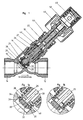
- valve 1 are opposite one another on a housing 10 of a valve Connection pieces 12 and 14 indicated, which lead to the strand or to the consumer.
- On obliquely directed screw socket 16 serves to receive a screwed Valve upper part 18.
- a valve seat 20 is formed against the a first closure piece 24 arranged on a hollow valve spindle 22 acts. in the In principle, the position of this first closure piece 24 determines the corresponding one Valve seat 20 is the default setting for the flow. With this first closure piece 24 the valve can also be shut off.
- the closure piece 25 is according to the enlargements Y in Fig. 1a 1b and includes:
- valve cone 26 One with a valve cone 26 via a valve rod 28 in drive connection standing closing body 30, which projects into the housing valve seat 20 and with a Leakage hole 32 is provided; a seat ring 34 loaded by spring 38, the one hand on the housing valve seat 20 or on the closing body 30 and on the other hand on the valve cone 26 can get to the system, the opposite end faces of the Specify valve cone 26 and the seat ring 34 a control gap.
- the upper edge of the seat ring 34 works here as a further valve seat 40 with the Lower edge of the valve cone 26 together.
- Fig. 1a shows the position of the closure piece 25 at a temperature of 53-55 ° C.
- the water flows through the leakage hole 32 and over the valve seat 20.
- the expansion element closes thermally Control attachment by advancing the valve cone to the valve seat 20. Only one flows minimal amount of water through the leakage hole 32. Is increased by increasing the Water temperature to more than 60 ° C initiated thermal disinfection, so pushes the expansion element continues the valve cone, so that the valve seat 39 between Closing body 30 and seat ring 34 is opened. If the disinfection temperature of 70 ° C is reached. this is what is required to keep the temperature constant
- the amount of water on the valve seat 40 between the seat ring 34 and valve cone 26 is regulated.
- the elements still designated in FIG. 1 relate to a seal 42, a Adjusting nut 44, a handwheel 46 and one in a thermal control attachment 48 arranged expansion element 50, the structure and mode of operation are of a known nature. In this case, this is caused in particular by the expansion element 50 felt water temperature the adjustment of the valve cone 26 and the different Positions of the elements of the second closure piece 25.
- valve cone 26 'in FIG. 2 projects with its hollow lower part up to the area of the valve seat 20 and forms a second modified closure piece 25 '.
- This modified closure piece 25 ' has at the lower end of the hollow valve cone 26 'a circumferential first throttle edge 52 with which the valve cone in and through the Housing valve seat 20 can grip. At a distance behind the first throttle edge 52 is one second circumferential throttle edge 54 arranged on the valve cone 26 'on the Housing valve seat 20 can get to the system. Between the two rotating ones Throttle edges 52, 54 there is a constriction 56 on the valve cone 26 '.
- FIG. 2a shows the position of the closure piece 25 'at a water temperature of 53- 55 ° C.
- the valve is open and water flows through the valve seat 20.
- the expansion element throttles in the thermal Control attachment by advancing the valve cone that flowing through the valve Amount of water to a minimum.
- the water flows through the narrow annular gap between the throttle edge 52 and the valve seat 20.
- the amount of water increases. This corresponds to an intermediate position between Figures 2a and 2b, in particular the constriction 56 for the enlarged passage cross section provides. If the disinfection temperature of 70 ° C is reached, it becomes Maintaining the temperature required amount of water between the throttle edge 54th and the valve seat 20, as shown in Fig. 2b.
- FIGs 3, 3a and 3b show a variant compared to Figures 2, 2a and 2b, in which the valve seat was modified.
- the valve cone 26 ' is on its front edge a circumferential throttle edge 52 which extend through the valve seat 20 can and with a second throttle edge 54 arranged behind, the diameter is larger than the diameter of the valve seat 20, being between the two throttle edges 52, 54 a constriction 56 is provided.
- the valve seat is modified and now includes in addition to the valve seat 20 in the closing direction behind it further valve seat 20 'with a reduced diameter. being between the two Valve seats 20, 20 'have a constriction 58 arranged in the valve housing 10.
- the water flows according to Fig. 3a between the valve seat 20 and the front throttle edge 52.
- the expansion element in the thermal control attachment closes the set temperature of 55 ° C by advancing the valve cone 26 ', the valve seat 20, so that only water over the annular gap between the throttle edge 52 and the valve seat 20 flows.
- Will through Increasing the water temperature to more than 60 ° C initiated thermal disinfection, so the expansion element pushes the valve cone forward and through the valve flowing water increases. This corresponds to an intermediate position between the Figures 3a and 3b. in particular the constriction 56 and groove 58 for the enlarged flow cross section ensures.
- the disinfection temperature is 70 ° C reached, the amount of water required to keep the temperature constant regulated between the throttle edge 52 and the further valve seat 20 ', as shown in Fig. 3b is shown.
Landscapes
- Engineering & Computer Science (AREA)
- General Engineering & Computer Science (AREA)
- Mechanical Engineering (AREA)
- Physics & Mathematics (AREA)
- General Physics & Mathematics (AREA)
- Fluid Mechanics (AREA)
- Automation & Control Theory (AREA)
- Thermal Sciences (AREA)
- Chemical & Material Sciences (AREA)
- Combustion & Propulsion (AREA)
- Temperature-Responsive Valves (AREA)
- Multiple-Way Valves (AREA)
- Lift Valve (AREA)
- Details Of Fluid Heaters (AREA)
Description
- Fig. 1
- einen Längsschnitt durch ein Ventil mit Thermostatregler gemäß einer Ausführungsform, die nicht Bestandteil der Erfindung
- Fig. 1a
- einen vergrößerten Ausschnitt Y aus Fig. 1 zur Veranschaulichung der Ventilstellung bei einer Wassertemperatur von 53 bis 55°C:
- Fig. 1b
- den gleichen Ausschnitt zur Veranschaulichung der Ventilstellung bei einer Wassertemperatur von 70°C;
- Fig. 2
- einen Längsschnitt durch ein Ventil mit Thermostatregler gemäß einer ersten erfindungsgemäßen Ausführungsform;
- Fig. 2a
- einen vergrößerten Querschnitt Y aus Fig. 2 zur Veranschaulichung der Ventilstellung bei einer Wassertemperatur von 53 - 55°C;
- Fig. 2b
- den gleichen Ausschnitt zur Veranschaulichung der Ventilstellung bei einer Wassertemperatur von 70°C;
- Fig. 3
- einen Längsschnitt durch ein Ventil mit Thermostatregler gemäß einer zweiten erfindungsgemäßen Ausführungsform;
- Fig. 3a
- einen vergrößerten Ausschnitt Y aus Fig. 3 zur Veranschaulichung der Ventilstellung bei einer Wassertemperatur von 53 - 55°C; und
- Fig. 3b
- den gleichen Ausschnitt zur Veranschaulichung der Ventilstellung bei einer Wassertemperatur von 70°C.
Claims (2)
- Ventil für Warmwasseranlagen, bei dem an einem Gehäuse (10) ein Anschlussstutzen (14) zum Strang, ein Anschlussstutzen (12) zum Verbraucher und ein Schraubstutzen zur Aufnahme eines Ventiloberteiles (18) mit einem an einer hohlen Ventilspindel (22) angeordneten ersten Verschlussstück (24), welches mit einem Ventilsitz im Gehäuse eine drosselartige Voreinstellung für den Durchfluß bildet, vorgesehen sind und in der hohlen Ventilspindel ein von außen gegen den Druck einer Feder betätigbares zweites Ventilverschlussstück (25',25") gegenüber einem entsprechenden Ventilsitz in der Ventilspindel von außen verschiebbar ist zur Entleerung eines Stranges über die Ventilspindel, wobei dieses zweite Ventilverschlussstück mit seinem dem Entleerungsventilsitz gegenüberliegenden Ende durch das erste Ventilverschlussstück hindurch in Richtung auf den Gehäuseventilsitz verschiebbar ist und bei dem auf die Ventilspindel ein Thermostatregler (48) mit seinem Gehäuse aufgeschraubt ist mit einem gegen einem Überhubfeder wirkenden Dehnstoffelement (50), dessen Kolben über einen Ventilkegel (2b') gegen das zweite Verschlussstück wirkt, dadurch gekennzeichnet, dass das zweite Verschlussstück (25', 25") umfasst:a) eine erste umlaufende Drosselkante (52) am Ventilkegel (26'), mit der er in und durch den Gehäuseventilsitz (20) greifen kann;b) eine zweite hinter der ersten Drosselkante (52) angeordnete umlaufende Drosselkante (54) am Ventilkegel (26'), die an dem Gehäuseventilsitz (20) zur Anlage gelangen kann; undc) eine Einschnürung (56) zwischen beiden umlaufenden Drosselkanten (52, 54).
- Ventil nach Anspruch 1 dadurch gekennzeichnet, dass das zweite Verschlussstück (25") umfassta) einen weiteren Gehäuseventilsitz (20') in Fließrichtung vor dem ersten Gehäuseventilsitz (20) dessen Durchmesser geringer als der Durchmesser der ersten Drosselkante (52) ist;b) und eine Einschnürung (58) zwischen beiden Gehäuseventilsitzen (20, 20').
Priority Applications (1)
| Application Number | Priority Date | Filing Date | Title |
|---|---|---|---|
| DE29924249U DE29924249U1 (de) | 1998-07-29 | 1999-07-24 | Ventil für Warmwasseranlagen |
Applications Claiming Priority (3)
| Application Number | Priority Date | Filing Date | Title |
|---|---|---|---|
| DE19834151 | 1998-07-29 | ||
| DE19834151A DE19834151C1 (de) | 1998-07-29 | 1998-07-29 | Ventil für Warmwasseranlagen |
| PCT/EP1999/005308 WO2000006931A1 (de) | 1998-07-29 | 1999-07-24 | Ventil für warmwasseranlagen |
Publications (2)
| Publication Number | Publication Date |
|---|---|
| EP1101054A1 EP1101054A1 (de) | 2001-05-23 |
| EP1101054B1 true EP1101054B1 (de) | 2004-01-21 |
Family
ID=7875716
Family Applications (1)
| Application Number | Title | Priority Date | Filing Date |
|---|---|---|---|
| EP99936605A Expired - Lifetime EP1101054B1 (de) | 1998-07-29 | 1999-07-24 | Ventil für warmwasseranlagen |
Country Status (6)
| Country | Link |
|---|---|
| EP (1) | EP1101054B1 (de) |
| JP (1) | JP2002521639A (de) |
| KR (1) | KR20010025000A (de) |
| AT (1) | ATE258287T1 (de) |
| DE (2) | DE19834151C1 (de) |
| WO (1) | WO2000006931A1 (de) |
Cited By (1)
| Publication number | Priority date | Publication date | Assignee | Title |
|---|---|---|---|---|
| EP2290492A1 (de) | 2009-08-24 | 2011-03-02 | Honeywell Technologies Sarl | Drosselventil, insbesondere Umlaufdrosselventil |
Families Citing this family (25)
| Publication number | Priority date | Publication date | Assignee | Title |
|---|---|---|---|---|
| DE10011558A1 (de) * | 2000-03-09 | 2001-09-27 | Danfoss Iwk Regler Gmbh | Regelventil |
| DE10056715C5 (de) * | 2000-11-15 | 2008-03-06 | F.W. Oventrop Gmbh & Co. Kg | Ventil für Warmwasseranlagen |
| DE10226289C1 (de) | 2002-06-13 | 2003-12-11 | Kemper Gebr Gmbh & Co Kg | Regulierventil für Warmwasser-Zirkulationssysteme |
| EP1394647A3 (de) | 2002-07-18 | 2006-07-19 | Gebr. Kemper GmbH + Co. KG | Stockwerkregulierventil für Warmwasser-Zirkulationssysteme |
| EP1385072B1 (de) * | 2002-07-18 | 2009-03-25 | Gebr. Kemper GmbH + Co. KG Metallwerke | Regulierventil |
| DE102006059577B4 (de) * | 2005-08-16 | 2014-05-28 | F.W. Oventrop Gmbh & Co. Kg | Ventil |
| CH700118B1 (de) | 2007-01-22 | 2010-06-30 | Fischer Georg Jrg Ag | Regelventil und damit aufgebaute Zirkulationsregelung für einen Warmwasserkreislauf. |
| WO2008092594A1 (de) * | 2007-01-31 | 2008-08-07 | Ixetic Hückeswagen Gmbh | Temperaturschaltventileinrichtung |
| EP2006589B1 (de) | 2007-06-22 | 2011-08-31 | Tenaris Connections Aktiengesellschaft | Gewindeverbindungsstück mit aktivierbarer Dichtung |
| EP2017507B1 (de) | 2007-07-16 | 2016-06-01 | Tenaris Connections Limited | Gewindeverbindungsstück mit elastischem Dichtungsring |
| DE102008012153A1 (de) | 2008-03-01 | 2009-09-10 | F.W. Oventrop Gmbh & Co. Kg | Einbauventil |
| EP2243920A1 (de) | 2009-04-22 | 2010-10-27 | Tenaris Connections Aktiengesellschaft | Gewindeverbindung für Röhren, Leitungen und dergleichen |
| EP2325435B2 (de) | 2009-11-24 | 2020-09-30 | Tenaris Connections B.V. | Verschraubung für [ultrahoch] abgedichteten internen und externen Druck |
| DE102009055936B4 (de) * | 2009-11-26 | 2024-11-28 | IMI Hydronic Engineering Deutschland GmbH | Zweiwege-Rücklauftemperaturregelventil für Kühlanlagen |
| EP2372211B1 (de) | 2010-03-26 | 2015-06-03 | Tenaris Connections Ltd. | Dünnwandige Rohrverbindung und Verfahren zum Verbinden eines ersten Rohres mit einem zweiten Rohr |
| US9163296B2 (en) | 2011-01-25 | 2015-10-20 | Tenaris Coiled Tubes, Llc | Coiled tube with varying mechanical properties for superior performance and methods to produce the same by a continuous heat treatment |
| BR112015016765A2 (pt) | 2013-01-11 | 2017-07-11 | Tenaris Connections Ltd | conexão de tubos de perfuração, tubo de perfuração correspondente e método para montar tubos de perfuração |
| US9803256B2 (en) | 2013-03-14 | 2017-10-31 | Tenaris Coiled Tubes, Llc | High performance material for coiled tubing applications and the method of producing the same |
| EP2789700A1 (de) | 2013-04-08 | 2014-10-15 | DALMINE S.p.A. | Dickwandige vergütete und nahtlose Stahlrohre und entsprechendes Verfahren zur Herstellung der Stahlrohre |
| EP2789701A1 (de) | 2013-04-08 | 2014-10-15 | DALMINE S.p.A. | Hochfeste mittelwandige vergütete und nahtlose Stahlrohre und entsprechendes Verfahren zur Herstellung der Stahlrohre |
| US9482357B2 (en) * | 2013-05-29 | 2016-11-01 | Baker Products Ltd. | Temperature controlled purge valve for use in water systems |
| KR102197204B1 (ko) | 2013-06-25 | 2021-01-04 | 테나리스 커넥션즈 비.브이. | 고크롬 내열철강 |
| US20160305192A1 (en) | 2015-04-14 | 2016-10-20 | Tenaris Connections Limited | Ultra-fine grained steels having corrosion-fatigue resistance |
| US11124852B2 (en) | 2016-08-12 | 2021-09-21 | Tenaris Coiled Tubes, Llc | Method and system for manufacturing coiled tubing |
| DE202022101366U1 (de) | 2022-03-14 | 2023-06-20 | Gebr. Kemper Gmbh + Co. Kg | Regulierventil für Wasser-Zirkulationssysteme |
Family Cites Families (11)
| Publication number | Priority date | Publication date | Assignee | Title |
|---|---|---|---|---|
| DE2351715A1 (de) * | 1973-10-15 | 1975-04-24 | Gerdts Gustav F Kg | Drosselventil |
| US4220178A (en) * | 1979-01-31 | 1980-09-02 | The Cessna Aircraft Company | Momentum balance spool |
| DE2929352A1 (de) * | 1979-07-20 | 1981-02-05 | Rexroth Gmbh G L | Druckmittelventil |
| FR2573841B1 (fr) * | 1984-11-29 | 1987-10-09 | Outillage Air Comprime | Dispositif hydraulique comportant un tiroir mobile dans un corps sous l'effet d'un organe de commande |
| DE3800715A1 (de) * | 1988-01-13 | 1989-07-27 | Kloeckner Humboldt Deutz Ag | Temperaturabhaengiges mengenregelventil |
| DE3916222A1 (de) * | 1989-05-18 | 1990-11-22 | Marita Engelhardt | Warmwasserversorgungsanlage |
| DE4231239A1 (de) * | 1992-09-18 | 1994-03-24 | Bosch Gmbh Robert | Vorrichtung zur Regelung der Leerlaufdrehzahl einer Brennkraftmaschine |
| DE9420413U1 (de) | 1994-12-21 | 1995-02-16 | Gebrüder Trox, GmbH, 47506 Neukirchen-Vluyn | Düseneinrichtung zur Belüftung von Räumen mit einem Einbaurahmen und einer schwenkbaren Düse, die eine äußere Führungswand und eine innere Düsenwand aufweist |
| DE9420412U1 (de) * | 1994-12-21 | 1995-02-16 | Metallwerke Neheim Goeke & Co Gmbh, 59755 Arnsberg | Ventil für Heizungs-, Warmwasser- oder Kühlanlagen |
| DE19519816A1 (de) * | 1995-05-31 | 1996-12-05 | Grohe Armaturen Friedrich | Stellgriff |
| DE19643902C2 (de) * | 1996-10-30 | 2002-05-23 | Kermi Gmbh | Ventileinrichtung sowie Heizkörper mit dieser |
-
1998
- 1998-07-29 DE DE19834151A patent/DE19834151C1/de not_active Expired - Fee Related
-
1999
- 1999-07-24 WO PCT/EP1999/005308 patent/WO2000006931A1/de not_active Ceased
- 1999-07-24 JP JP2000562685A patent/JP2002521639A/ja active Pending
- 1999-07-24 EP EP99936605A patent/EP1101054B1/de not_active Expired - Lifetime
- 1999-07-24 AT AT99936605T patent/ATE258287T1/de not_active IP Right Cessation
- 1999-07-24 DE DE59908377T patent/DE59908377D1/de not_active Expired - Lifetime
- 1999-07-24 KR KR1020007012540A patent/KR20010025000A/ko not_active Withdrawn
Cited By (1)
| Publication number | Priority date | Publication date | Assignee | Title |
|---|---|---|---|---|
| EP2290492A1 (de) | 2009-08-24 | 2011-03-02 | Honeywell Technologies Sarl | Drosselventil, insbesondere Umlaufdrosselventil |
Also Published As
| Publication number | Publication date |
|---|---|
| DE59908377D1 (de) | 2004-02-26 |
| DE19834151C1 (de) | 2000-04-13 |
| EP1101054A1 (de) | 2001-05-23 |
| JP2002521639A (ja) | 2002-07-16 |
| KR20010025000A (ko) | 2001-03-26 |
| ATE258287T1 (de) | 2004-02-15 |
| WO2000006931A1 (de) | 2000-02-10 |
Similar Documents
| Publication | Publication Date | Title |
|---|---|---|
| DE19834151C1 (de) | Ventil für Warmwasseranlagen | |
| EP3420430B1 (de) | Thermostat-mischventil | |
| DE69405286T2 (de) | Wassererhitzer | |
| DE10256035B3 (de) | Wärmetauscher-Ventilanordnung, insbesondere Heizkörper-Ventilanordnung | |
| CH708204A1 (de) | Druckausgleichseinsatz. | |
| DE69306461T2 (de) | Ventilanordnung für Anlagen, die sowohl für Heizungs- als auch für Haushaltsheisswasser vorgesehen ist | |
| DE112016006072T5 (de) | Flüssigkeits-Steuerventilvorrichtung für eine Mischbatterie | |
| DE2153286A1 (de) | ||
| DE4124304C2 (de) | Thermostatisch betätigbares Dreiwege-Heizkörperventil für Einrohrheizungsanlagen | |
| DE4107969A1 (de) | Thermostat-ventilunterteil | |
| DE69609580T2 (de) | Nicht verkalkender Thermostatmischer | |
| WO1994018509A1 (de) | Adapterarmatur zum wahlweisen anschluss eines heizkörpers | |
| EP1128104B1 (de) | Thermostatgeregelte Mischbatterie | |
| DE29924249U1 (de) | Ventil für Warmwasseranlagen | |
| EP1239238B1 (de) | Anschlussarmatur für einen Heizkörper | |
| DE4106278C2 (de) | Heizungsventil | |
| DE4407447A1 (de) | Voreinstellbares Regulierventil | |
| DE69534320T2 (de) | Ventil für ein wärmeträgersystem | |
| DE3743707C2 (de) | Ventil mit Voreinstellung der Durchflußmenge | |
| DE10132001C2 (de) | Thermostatischer Regler zur Regelung der Durchflussmenge eines Fluids | |
| DE4303483C2 (de) | Regler | |
| DE20321608U1 (de) | Regulierventil | |
| DE60119258T2 (de) | Ventil zur Regelung der Strömungsgschwindigkeit eines Fluids für einen Plattenheizkörper oder dergleichen | |
| DE3112138A1 (de) | "thermostatisch betaetigtes ventil" | |
| CH682510A5 (de) | Elektrisch betätigtes Ventil. |
Legal Events
| Date | Code | Title | Description |
|---|---|---|---|
| PUAI | Public reference made under article 153(3) epc to a published international application that has entered the european phase |
Free format text: ORIGINAL CODE: 0009012 |
|
| 17P | Request for examination filed |
Effective date: 20000810 |
|
| AK | Designated contracting states |
Kind code of ref document: A1 Designated state(s): AT BE CH CY DE DK ES FI FR GB GR IE IT LI LU MC NL PT SE |
|
| 17Q | First examination report despatched |
Effective date: 20021205 |
|
| GRAP | Despatch of communication of intention to grant a patent |
Free format text: ORIGINAL CODE: EPIDOSNIGR1 |
|
| GRAS | Grant fee paid |
Free format text: ORIGINAL CODE: EPIDOSNIGR3 |
|
| GRAA | (expected) grant |
Free format text: ORIGINAL CODE: 0009210 |
|
| AK | Designated contracting states |
Kind code of ref document: B1 Designated state(s): AT BE CH CY DE DK ES FI FR GB GR IE IT LI LU MC NL PT SE |
|
| PG25 | Lapsed in a contracting state [announced via postgrant information from national office to epo] |
Ref country code: IT Free format text: LAPSE BECAUSE OF FAILURE TO SUBMIT A TRANSLATION OF THE DESCRIPTION OR TO PAY THE FEE WITHIN THE PRE;WARNING: LAPSES OF ITALIAN PATENTS WITH EFFECTIVE DATE BEFORE 2007 MAY HAVE OCCURRED AT ANY TIME BEFORE 2007. THE CORRECT EFFECTIVE DATE MAY BE DIFFERENT FROM THE ONE RECORDED.SCRIBED TIME-LIMIT Effective date: 20040121 Ref country code: FI Free format text: LAPSE BECAUSE OF FAILURE TO SUBMIT A TRANSLATION OF THE DESCRIPTION OR TO PAY THE FEE WITHIN THE PRESCRIBED TIME-LIMIT Effective date: 20040121 Ref country code: ES Free format text: LAPSE BECAUSE OF FAILURE TO SUBMIT A TRANSLATION OF THE DESCRIPTION OR TO PAY THE FEE WITHIN THE PRESCRIBED TIME-LIMIT Effective date: 20040121 Ref country code: CY Free format text: LAPSE BECAUSE OF FAILURE TO SUBMIT A TRANSLATION OF THE DESCRIPTION OR TO PAY THE FEE WITHIN THE PRESCRIBED TIME-LIMIT Effective date: 20040121 |
|
| REG | Reference to a national code |
Ref country code: GB Ref legal event code: FG4D Free format text: NOT ENGLISH |
|
| REG | Reference to a national code |
Ref country code: CH Ref legal event code: EP |
|
| REG | Reference to a national code |
Ref country code: IE Ref legal event code: FG4D Free format text: GERMAN |
|
| REF | Corresponds to: |
Ref document number: 59908377 Country of ref document: DE Date of ref document: 20040226 Kind code of ref document: P |
|
| PG25 | Lapsed in a contracting state [announced via postgrant information from national office to epo] |
Ref country code: SE Free format text: LAPSE BECAUSE OF FAILURE TO SUBMIT A TRANSLATION OF THE DESCRIPTION OR TO PAY THE FEE WITHIN THE PRESCRIBED TIME-LIMIT Effective date: 20040421 Ref country code: GR Free format text: LAPSE BECAUSE OF FAILURE TO SUBMIT A TRANSLATION OF THE DESCRIPTION OR TO PAY THE FEE WITHIN THE PRESCRIBED TIME-LIMIT Effective date: 20040421 Ref country code: DK Free format text: LAPSE BECAUSE OF FAILURE TO SUBMIT A TRANSLATION OF THE DESCRIPTION OR TO PAY THE FEE WITHIN THE PRESCRIBED TIME-LIMIT Effective date: 20040421 |
|
| GBT | Gb: translation of ep patent filed (gb section 77(6)(a)/1977) |
Effective date: 20040401 |
|
| PG25 | Lapsed in a contracting state [announced via postgrant information from national office to epo] |
Ref country code: LU Free format text: LAPSE BECAUSE OF NON-PAYMENT OF DUE FEES Effective date: 20040724 |
|
| PG25 | Lapsed in a contracting state [announced via postgrant information from national office to epo] |
Ref country code: MC Free format text: LAPSE BECAUSE OF NON-PAYMENT OF DUE FEES Effective date: 20040731 |
|
| ET | Fr: translation filed | ||
| PLBE | No opposition filed within time limit |
Free format text: ORIGINAL CODE: 0009261 |
|
| STAA | Information on the status of an ep patent application or granted ep patent |
Free format text: STATUS: NO OPPOSITION FILED WITHIN TIME LIMIT |
|
| 26N | No opposition filed |
Effective date: 20041022 |
|
| REG | Reference to a national code |
Ref country code: CH Ref legal event code: NV Representative=s name: R. A. EGLI & CO. PATENTANWAELTE |
|
| REG | Reference to a national code |
Ref country code: CH Ref legal event code: PUE Owner name: HONEYWELL TECHNOLOGIES SARL Free format text: HONEYWELL AG#KAISERLEISTRASSE 39#63067 OFFENBACH AM MAIN (DE) -TRANSFER TO- HONEYWELL TECHNOLOGIES SARL#AVENUE DE LA GOTTAZ 34-36#1110 MORGES (CH) |
|
| PGFP | Annual fee paid to national office [announced via postgrant information from national office to epo] |
Ref country code: AT Payment date: 20060614 Year of fee payment: 8 |
|
| PGFP | Annual fee paid to national office [announced via postgrant information from national office to epo] |
Ref country code: FR Payment date: 20060705 Year of fee payment: 8 |
|
| PGFP | Annual fee paid to national office [announced via postgrant information from national office to epo] |
Ref country code: CH Payment date: 20060707 Year of fee payment: 8 |
|
| PGFP | Annual fee paid to national office [announced via postgrant information from national office to epo] |
Ref country code: IE Payment date: 20060720 Year of fee payment: 8 |
|
| REG | Reference to a national code |
Ref country code: GB Ref legal event code: 732E |
|
| BECH | Be: change of holder |
Owner name: HONEYWELL TECHNOLOGIES SARL Effective date: 20071219 |
|
| PG25 | Lapsed in a contracting state [announced via postgrant information from national office to epo] |
Ref country code: PT Free format text: LAPSE BECAUSE OF NON-PAYMENT OF DUE FEES Effective date: 20040621 |
|
| REG | Reference to a national code |
Ref country code: CH Ref legal event code: PL |
|
| PG25 | Lapsed in a contracting state [announced via postgrant information from national office to epo] |
Ref country code: LI Free format text: LAPSE BECAUSE OF NON-PAYMENT OF DUE FEES Effective date: 20070731 Ref country code: CH Free format text: LAPSE BECAUSE OF NON-PAYMENT OF DUE FEES Effective date: 20070731 |
|
| REG | Reference to a national code |
Ref country code: IE Ref legal event code: MM4A |
|
| REG | Reference to a national code |
Ref country code: FR Ref legal event code: ST Effective date: 20080331 |
|
| PG25 | Lapsed in a contracting state [announced via postgrant information from national office to epo] |
Ref country code: AT Free format text: LAPSE BECAUSE OF NON-PAYMENT OF DUE FEES Effective date: 20070724 |
|
| PG25 | Lapsed in a contracting state [announced via postgrant information from national office to epo] |
Ref country code: FR Free format text: LAPSE BECAUSE OF NON-PAYMENT OF DUE FEES Effective date: 20070731 |
|
| PG25 | Lapsed in a contracting state [announced via postgrant information from national office to epo] |
Ref country code: IE Free format text: LAPSE BECAUSE OF NON-PAYMENT OF DUE FEES Effective date: 20070724 |
|
| NLS | Nl: assignments of ep-patents |
Owner name: HONEYWELL TECHNOLOGIES SARL Effective date: 20081008 |
|
| PGFP | Annual fee paid to national office [announced via postgrant information from national office to epo] |
Ref country code: NL Payment date: 20180724 Year of fee payment: 20 |
|
| PGFP | Annual fee paid to national office [announced via postgrant information from national office to epo] |
Ref country code: GB Payment date: 20180731 Year of fee payment: 20 Ref country code: BE Payment date: 20180725 Year of fee payment: 20 |
|
| PGFP | Annual fee paid to national office [announced via postgrant information from national office to epo] |
Ref country code: DE Payment date: 20180928 Year of fee payment: 20 |
|
| REG | Reference to a national code |
Ref country code: DE Ref legal event code: R071 Ref document number: 59908377 Country of ref document: DE Ref country code: NL Ref legal event code: MK Effective date: 20190723 |
|
| REG | Reference to a national code |
Ref country code: GB Ref legal event code: PE20 Expiry date: 20190723 |
|
| REG | Reference to a national code |
Ref country code: BE Ref legal event code: MK Effective date: 20190724 |
|
| PG25 | Lapsed in a contracting state [announced via postgrant information from national office to epo] |
Ref country code: GB Free format text: LAPSE BECAUSE OF EXPIRATION OF PROTECTION Effective date: 20190723 |