EP1101425A1 - Verstellbares Aufbausystem auf Profilelementen - Google Patents
Verstellbares Aufbausystem auf Profilelementen Download PDFInfo
- Publication number
- EP1101425A1 EP1101425A1 EP00203931A EP00203931A EP1101425A1 EP 1101425 A1 EP1101425 A1 EP 1101425A1 EP 00203931 A EP00203931 A EP 00203931A EP 00203931 A EP00203931 A EP 00203931A EP 1101425 A1 EP1101425 A1 EP 1101425A1
- Authority
- EP
- European Patent Office
- Prior art keywords
- perforations
- bar
- section
- bars
- profiles
- Prior art date
- Legal status (The legal status is an assumption and is not a legal conclusion. Google has not performed a legal analysis and makes no representation as to the accuracy of the status listed.)
- Withdrawn
Links
- 230000037431 insertion Effects 0.000 claims 1
- 238000003780 insertion Methods 0.000 claims 1
- 230000005484 gravity Effects 0.000 abstract 1
- 238000004519 manufacturing process Methods 0.000 description 3
- 244000245420 ail Species 0.000 description 2
- 239000002184 metal Substances 0.000 description 2
- 230000000712 assembly Effects 0.000 description 1
- 238000000429 assembly Methods 0.000 description 1
- 238000004140 cleaning Methods 0.000 description 1
- 239000000470 constituent Substances 0.000 description 1
- 238000005520 cutting process Methods 0.000 description 1
- 238000006073 displacement reaction Methods 0.000 description 1
- 238000003754 machining Methods 0.000 description 1
- 238000012423 maintenance Methods 0.000 description 1
- 239000000463 material Substances 0.000 description 1
- 238000003801 milling Methods 0.000 description 1
- 239000003973 paint Substances 0.000 description 1
- 238000000926 separation method Methods 0.000 description 1
- 238000003860 storage Methods 0.000 description 1
Images



Classifications
-
- A—HUMAN NECESSITIES
- A47—FURNITURE; DOMESTIC ARTICLES OR APPLIANCES; COFFEE MILLS; SPICE MILLS; SUCTION CLEANERS IN GENERAL
- A47B—TABLES; DESKS; OFFICE FURNITURE; CABINETS; DRAWERS; GENERAL DETAILS OF FURNITURE
- A47B57/00—Cabinets, racks or shelf units, characterised by features for adjusting shelves or partitions
- A47B57/30—Cabinets, racks or shelf units, characterised by features for adjusting shelves or partitions with means for adjusting the height of detachable shelf supports
- A47B57/48—Cabinets, racks or shelf units, characterised by features for adjusting shelves or partitions with means for adjusting the height of detachable shelf supports consisting of tongues, pins or similar projecting means coacting with openings
- A47B57/485—Straight pins
- A47B57/487—Straight pins with varying cross-section
-
- A—HUMAN NECESSITIES
- A47—FURNITURE; DOMESTIC ARTICLES OR APPLIANCES; COFFEE MILLS; SPICE MILLS; SUCTION CLEANERS IN GENERAL
- A47B—TABLES; DESKS; OFFICE FURNITURE; CABINETS; DRAWERS; GENERAL DETAILS OF FURNITURE
- A47B57/00—Cabinets, racks or shelf units, characterised by features for adjusting shelves or partitions
- A47B57/30—Cabinets, racks or shelf units, characterised by features for adjusting shelves or partitions with means for adjusting the height of detachable shelf supports
- A47B57/36—Cabinets, racks or shelf units, characterised by features for adjusting shelves or partitions with means for adjusting the height of detachable shelf supports consisting of side walls of the ladder type
- A47B57/38—Cabinets, racks or shelf units, characterised by features for adjusting shelves or partitions with means for adjusting the height of detachable shelf supports consisting of side walls of the ladder type with hooks on the shelf supports to engage the rungs of the ladder
Definitions
- the present invention relates to a system for axially adjustable fixing on profiles, usable for example for a rack, for a shelf, for a wardrobe, for tilting shelving, for scaffolding, for a ladder, etc.
- EP 0 927 533 A1 describes such a system ensuring good rigidity at the set but which requires three different pieces suitable for connecting horizontal elements to uprights, as well as the timing of these connections. These parts have a profile requiring special machining, hence a high cost price.
- the object of the invention is to provide a system for fixing allowing easy assembly and disassembly, without require tools, and whose manufacture is simple and inexpensive.
- the profile may in particular have a section essentially U-shaped. This profile can be placed vertically, horizontally or obliquely, depending the use for which the system is intended.
- the profile can also consist of two L-shaped sections, including the coplanar stems of these L form the base and whose wings of these L, arranged in parallel, carry the perforations opposite.
- the stems of these L are joined together in a known manner.
- the perforations are preferably circular, but can be for example oval, square, rectangular, triangular, buttonhole, etc.
- the bar has a section corresponding to that of perforations and preferably a circular section.
- the bar rests in the perforations opposite the or profiles through two grooves spaced near the ends of the bar and spaced apart of a length corresponding to the distance between two opposite perforations. These grooves can extend over the entire periphery of the bar or over a part only of it.
- the tab inserted between the bar and the base of the or profiles, ensures an offset of the bar by compared to the perforations opposite, preventing the separation of the device.
- the retainer of the leg has a length in relation to the load that the latter must endure.
- a horizontal element can also rest on the bar via the tab.
- An advantage of the invention is that the removing the tab is enough to unlock the bar, the disassembly of the assembly being carried out therefore very easily by hand. Furthermore, the simple weight of the bar is sufficient to ensure its temporary maintenance in position.
- Another advantage of the invention lies in the simplicity of manufacture of its constituent elements.
- the bars can be obtained by cutting a bar, and the grooves obtained by milling. These operations are particularly easy to perform in the case of cylindrical bars.
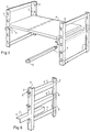
- Fig. 1 shows a binding 1 in which a upright consists of a section 2 section essentially U-shaped.
- the section of this profile 2 is consisting of a middle part (or "base") and two wings substantially parallel.
- Each wing has 3 circular perforations opposite, at the same height, on the wings of the profile 2.
- the longitudinal setting of the bar 4 is provided by two grooves 6, made in the bar 4, dimensioned in such a way that the edge of the perforations 3 can engage, preventing any longitudinal displacement of the bar 4 when this one is slightly off center compared to the perforation 3.
- the width of the grooves 6 is determined by the thickness of the material of which the profile 2.
- the locking of the bar 4 in a such off-center position is ensured by a L-shaped tab 5, part of which is defined as “retainer") inserted between the base of the U-shaped section and the bar 4.
- the other part of tab 5 (defined as “support element") is available especially for receive a hook in a wardrobe, for fixing of a load, like cleat for a shelf board, etc.
- Figs. 2a, 2b, 2c and 2d show examples of production of bars 4 with two grooves 6, the sections are respectively circular, triangular, square and rectangular.
- Fig. 2nd shows the corresponding perforations 3 to these bars 4 in the wing of a section 2 in L.
- Figs. 3 and 4 show an exemplary embodiment allowing a double positioning of a shelf by pivoting around the axis that constitutes the bar 4.
- the tablet consisting of a panel 7 is enclosed between the two jaws forming the support element of the tab 8.
- the retaining element 9 has the shape of an L. When the tablet is in a horizontal position, the pole L press against the base of the section of section 2 and This prevents the tablet from tipping over. It is however possible, by shifting the tablet upwards, to make pivot the tab around the bar 4.
- the shelf can then be folded down as shown in Fig. 4. She however remains held in place by the flap lower 10 of the retainer 9.
- Fig. 5 shows an exemplary embodiment where the uprights are vertical profiles 2 with L-shaped section, arranged in such a way that the bases of the profiles 2 are coplanar, the wings of the profiles 2 being face.
- the horizontal element 7 consisting of a panel, rests on bars 4 with square section by via legs 5 in L. Bars 4 and 5 L-shaped legs have the required spacing to fit respectively in and between profiles 2 in L.
- These profiles 2 are here joined in pairs, so that constitute a simple and stable scaffolding.
- Fig. 6 shows an exemplary embodiment where each pair of perforations 3 receives a section bar 4 oval, allowing a double setting. On each bar 4 comes to place a leg 5 in L, of appropriate size relative to the spacing of the vertical profiles 2, so as to constitute a ladder.
- Fig. 7 shows a particular application of the device according to the invention, where a ladder section consists of a section 2 with a C section, fitted with perforations 3 in the wings of the profile 2.
- a tray able to pivot 11 around a horizontal axis perpendicular to profile 2 with C section, is fixed to tab 8 which blocks bar 4 in a pair of perforations 3 opposite.
- This swivel tray is likely to support tools, paint, etc.
- Fig. 8 shows an embodiment where the horizontal element is a shelf 7 made of stamped sheet metal.
- the edge of the shelf 7 has cutouts spaced so as to spare, between cutouts, a tongue 9, the end of which can be inserted between the base of the U and a bar 4.
Landscapes
- Furniture Connections (AREA)
- Ladders (AREA)
Applications Claiming Priority (2)
| Application Number | Priority Date | Filing Date | Title |
|---|---|---|---|
| BE9900750 | 1999-11-18 | ||
| BE9900750A BE1013142A5 (fr) | 1999-11-18 | 1999-11-18 | Systeme de fixation ajustable sur des profiles. |
Publications (1)
| Publication Number | Publication Date |
|---|---|
| EP1101425A1 true EP1101425A1 (de) | 2001-05-23 |
Family
ID=3892167
Family Applications (1)
| Application Number | Title | Priority Date | Filing Date |
|---|---|---|---|
| EP00203931A Withdrawn EP1101425A1 (de) | 1999-11-18 | 2000-11-08 | Verstellbares Aufbausystem auf Profilelementen |
Country Status (2)
| Country | Link |
|---|---|
| EP (1) | EP1101425A1 (de) |
| BE (1) | BE1013142A5 (de) |
Cited By (2)
| Publication number | Priority date | Publication date | Assignee | Title |
|---|---|---|---|---|
| FR2832603A1 (fr) * | 2001-11-23 | 2003-05-30 | Arnaud Duwicquet | Taquet support de rayon ou tablette |
| FR2942119A1 (fr) * | 2009-02-16 | 2010-08-20 | A5 Ind | Support pour etagere |
Citations (8)
| Publication number | Priority date | Publication date | Assignee | Title |
|---|---|---|---|---|
| FR587615A (fr) * | 1924-10-18 | 1925-04-21 | Perfectionnements apportés aux meubles métalliques | |
| US1886318A (en) * | 1929-03-29 | 1932-11-01 | Lyon Metal Products Inc | Shelf rack construction |
| FR79774E (fr) * | 1961-05-12 | 1963-01-25 | Casier métallique démontable | |
| CH379078A (it) * | 1960-03-03 | 1964-06-30 | Nember Fausto | Scaffalatura ad elementi componibili |
| GB2217185A (en) * | 1988-03-11 | 1989-10-25 | Twinlock Plc | Support members for storage systems |
| US5425520A (en) | 1992-03-18 | 1995-06-20 | Hideki Ueda | Corner bracket for use in a sectional shelf |
| DE19833962A1 (de) * | 1997-11-12 | 1999-05-20 | Liebherr Hausgeraete | Kühlschranktür |
| EP0927533A1 (de) | 1997-12-03 | 1999-07-07 | Avasco Industries | Verbindung zwischen einem senkrechten Ständer und einem Regal |
Family Cites Families (1)
| Publication number | Priority date | Publication date | Assignee | Title |
|---|---|---|---|---|
| FR2651655A1 (fr) * | 1989-09-13 | 1991-03-15 | Roumagere Louis | Dispositif d'assemblage d'elements notamment d'etageres. |
-
1999
- 1999-11-18 BE BE9900750A patent/BE1013142A5/fr not_active IP Right Cessation
-
2000
- 2000-11-08 EP EP00203931A patent/EP1101425A1/de not_active Withdrawn
Patent Citations (8)
| Publication number | Priority date | Publication date | Assignee | Title |
|---|---|---|---|---|
| FR587615A (fr) * | 1924-10-18 | 1925-04-21 | Perfectionnements apportés aux meubles métalliques | |
| US1886318A (en) * | 1929-03-29 | 1932-11-01 | Lyon Metal Products Inc | Shelf rack construction |
| CH379078A (it) * | 1960-03-03 | 1964-06-30 | Nember Fausto | Scaffalatura ad elementi componibili |
| FR79774E (fr) * | 1961-05-12 | 1963-01-25 | Casier métallique démontable | |
| GB2217185A (en) * | 1988-03-11 | 1989-10-25 | Twinlock Plc | Support members for storage systems |
| US5425520A (en) | 1992-03-18 | 1995-06-20 | Hideki Ueda | Corner bracket for use in a sectional shelf |
| DE19833962A1 (de) * | 1997-11-12 | 1999-05-20 | Liebherr Hausgeraete | Kühlschranktür |
| EP0927533A1 (de) | 1997-12-03 | 1999-07-07 | Avasco Industries | Verbindung zwischen einem senkrechten Ständer und einem Regal |
Cited By (2)
| Publication number | Priority date | Publication date | Assignee | Title |
|---|---|---|---|---|
| FR2832603A1 (fr) * | 2001-11-23 | 2003-05-30 | Arnaud Duwicquet | Taquet support de rayon ou tablette |
| FR2942119A1 (fr) * | 2009-02-16 | 2010-08-20 | A5 Ind | Support pour etagere |
Also Published As
| Publication number | Publication date |
|---|---|
| BE1013142A5 (fr) | 2001-10-02 |
Similar Documents
| Publication | Publication Date | Title |
|---|---|---|
| EP0049665B1 (de) | Schaugestell mit Fachböden | |
| FR2600726A2 (fr) | Dispositif d'assemblage d'ossature de stand pour exposition temporaire. | |
| FR2717994A1 (fr) | Etagère à surface variable. | |
| EP0900037A1 (de) | Zusammensetzbarer stuhl | |
| EP0307336B1 (de) | Element zum Ordnen von Dokumenten oder dergleichen und Zusammensetzung von geneigten Speichereinheiten, bestehend aus mehreren solchen Elementen | |
| EP3995045B1 (de) | Tisch mit mittelauszug | |
| FR2537906A1 (fr) | Ratelier a consoles | |
| WO1997027789A1 (fr) | Barquette-presentoir a largeur reglable | |
| BE1004312A5 (fr) | Meuble comportant une embase munie de roulettes. | |
| BE1013142A5 (fr) | Systeme de fixation ajustable sur des profiles. | |
| FR2862504A1 (fr) | Meuble de stockage et de presentation de produits | |
| EP1013197B1 (de) | Regale | |
| FR2826585A1 (fr) | Casier a skis ranges en oblique | |
| EP1656858B1 (de) | Auf einem Einzeler verschiebbar angeordnet einstellbarer Anschlag | |
| FR2956171A1 (fr) | Element pour dispositif d'agencement et dispositif d'agencement pourvu d'un tel element | |
| EP3248507B1 (de) | Verbindungselement und montagekit für möbel | |
| FR2731884A1 (fr) | Rayonnage modulaire adaptable | |
| EP1696771A1 (de) | Vorrichtung zur anzeige einer reihe von objekten | |
| FR2678813A1 (fr) | Perfectionnements aux dispositifs pour la presentation et le transport d'un appareil de television et d'un magnetoscope. | |
| FR2544458A1 (fr) | Support, notamment pour la presentation | |
| WO1990000684A1 (fr) | Systeme d'assemblage pour la realisation d'objets divers du type meuble notamment | |
| EP0392131B1 (de) | Tragarm für Fachboden | |
| FR2683128A1 (fr) | Structure de mobilier a reglage variable. | |
| EP0543692B1 (de) | Schauanordnung mit einem an vertikalen Kabeln oder Stangen befestigten Pfosten | |
| FR2517186A1 (fr) | Meuble de rangement modulaire et clips en permettant la realisation |
Legal Events
| Date | Code | Title | Description |
|---|---|---|---|
| PUAI | Public reference made under article 153(3) epc to a published international application that has entered the european phase |
Free format text: ORIGINAL CODE: 0009012 |
|
| AK | Designated contracting states |
Kind code of ref document: A1 Designated state(s): AT BE CH CY DE DK ES FI FR GB GR IE IT LI LU MC NL PT SE TR |
|
| AX | Request for extension of the european patent |
Free format text: AL;LT;LV;MK;RO;SI |
|
| 17P | Request for examination filed |
Effective date: 20010910 |
|
| AKX | Designation fees paid |
Free format text: AT BE CH CY DE DK ES FI FR GB GR IE IT LI LU MC NL PT SE TR |
|
| 17Q | First examination report despatched |
Effective date: 20030801 |
|
| GRAP | Despatch of communication of intention to grant a patent |
Free format text: ORIGINAL CODE: EPIDOSNIGR1 |
|
| STAA | Information on the status of an ep patent application or granted ep patent |
Free format text: STATUS: THE APPLICATION IS DEEMED TO BE WITHDRAWN |
|
| 18D | Application deemed to be withdrawn |
Effective date: 20040731 |