EP1101526A2 - Réacteur à fonctionnement discontinu avec alimentation de gaz réactifs sur demande - Google Patents
Réacteur à fonctionnement discontinu avec alimentation de gaz réactifs sur demande Download PDFInfo
- Publication number
- EP1101526A2 EP1101526A2 EP00125025A EP00125025A EP1101526A2 EP 1101526 A2 EP1101526 A2 EP 1101526A2 EP 00125025 A EP00125025 A EP 00125025A EP 00125025 A EP00125025 A EP 00125025A EP 1101526 A2 EP1101526 A2 EP 1101526A2
- Authority
- EP
- European Patent Office
- Prior art keywords
- gas
- liquid
- vessel
- reaction
- baffle
- Prior art date
- Legal status (The legal status is an assumption and is not a legal conclusion. Google has not performed a legal analysis and makes no representation as to the accuracy of the status listed.)
- Withdrawn
Links
Images



Classifications
-
- B—PERFORMING OPERATIONS; TRANSPORTING
- B01—PHYSICAL OR CHEMICAL PROCESSES OR APPARATUS IN GENERAL
- B01J—CHEMICAL OR PHYSICAL PROCESSES, e.g. CATALYSIS OR COLLOID CHEMISTRY; THEIR RELEVANT APPARATUS
- B01J19/00—Chemical, physical or physico-chemical processes in general; Their relevant apparatus
- B01J19/18—Stationary reactors having moving elements inside
- B01J19/1868—Stationary reactors having moving elements inside resulting in a loop-type movement
- B01J19/1875—Stationary reactors having moving elements inside resulting in a loop-type movement internally, i.e. the mixture circulating inside the vessel such that the upwards stream is separated physically from the downwards stream(s)
-
- B—PERFORMING OPERATIONS; TRANSPORTING
- B01—PHYSICAL OR CHEMICAL PROCESSES OR APPARATUS IN GENERAL
- B01F—MIXING, e.g. DISSOLVING, EMULSIFYING OR DISPERSING
- B01F23/00—Mixing according to the phases to be mixed, e.g. dispersing or emulsifying
- B01F23/20—Mixing gases with liquids
-
- B—PERFORMING OPERATIONS; TRANSPORTING
- B01—PHYSICAL OR CHEMICAL PROCESSES OR APPARATUS IN GENERAL
- B01F—MIXING, e.g. DISSOLVING, EMULSIFYING OR DISPERSING
- B01F23/00—Mixing according to the phases to be mixed, e.g. dispersing or emulsifying
- B01F23/20—Mixing gases with liquids
- B01F23/23—Mixing gases with liquids by introducing gases into liquid media, e.g. for producing aerated liquids
- B01F23/233—Mixing gases with liquids by introducing gases into liquid media, e.g. for producing aerated liquids using driven stirrers with completely immersed stirring elements
- B01F23/2331—Mixing gases with liquids by introducing gases into liquid media, e.g. for producing aerated liquids using driven stirrers with completely immersed stirring elements characterised by the introduction of the gas along the axis of the stirrer or along the stirrer elements
-
- B—PERFORMING OPERATIONS; TRANSPORTING
- B01—PHYSICAL OR CHEMICAL PROCESSES OR APPARATUS IN GENERAL
- B01F—MIXING, e.g. DISSOLVING, EMULSIFYING OR DISPERSING
- B01F23/00—Mixing according to the phases to be mixed, e.g. dispersing or emulsifying
- B01F23/20—Mixing gases with liquids
- B01F23/23—Mixing gases with liquids by introducing gases into liquid media, e.g. for producing aerated liquids
- B01F23/233—Mixing gases with liquids by introducing gases into liquid media, e.g. for producing aerated liquids using driven stirrers with completely immersed stirring elements
- B01F23/2331—Mixing gases with liquids by introducing gases into liquid media, e.g. for producing aerated liquids using driven stirrers with completely immersed stirring elements characterised by the introduction of the gas along the axis of the stirrer or along the stirrer elements
- B01F23/23311—Mixing gases with liquids by introducing gases into liquid media, e.g. for producing aerated liquids using driven stirrers with completely immersed stirring elements characterised by the introduction of the gas along the axis of the stirrer or along the stirrer elements through a hollow stirrer axis
-
- B—PERFORMING OPERATIONS; TRANSPORTING
- B01—PHYSICAL OR CHEMICAL PROCESSES OR APPARATUS IN GENERAL
- B01F—MIXING, e.g. DISSOLVING, EMULSIFYING OR DISPERSING
- B01F23/00—Mixing according to the phases to be mixed, e.g. dispersing or emulsifying
- B01F23/20—Mixing gases with liquids
- B01F23/23—Mixing gases with liquids by introducing gases into liquid media, e.g. for producing aerated liquids
- B01F23/233—Mixing gases with liquids by introducing gases into liquid media, e.g. for producing aerated liquids using driven stirrers with completely immersed stirring elements
- B01F23/2331—Mixing gases with liquids by introducing gases into liquid media, e.g. for producing aerated liquids using driven stirrers with completely immersed stirring elements characterised by the introduction of the gas along the axis of the stirrer or along the stirrer elements
- B01F23/23314—Mixing gases with liquids by introducing gases into liquid media, e.g. for producing aerated liquids using driven stirrers with completely immersed stirring elements characterised by the introduction of the gas along the axis of the stirrer or along the stirrer elements through a hollow stirrer element
-
- B—PERFORMING OPERATIONS; TRANSPORTING
- B01—PHYSICAL OR CHEMICAL PROCESSES OR APPARATUS IN GENERAL
- B01F—MIXING, e.g. DISSOLVING, EMULSIFYING OR DISPERSING
- B01F23/00—Mixing according to the phases to be mixed, e.g. dispersing or emulsifying
- B01F23/20—Mixing gases with liquids
- B01F23/23—Mixing gases with liquids by introducing gases into liquid media, e.g. for producing aerated liquids
- B01F23/233—Mixing gases with liquids by introducing gases into liquid media, e.g. for producing aerated liquids using driven stirrers with completely immersed stirring elements
- B01F23/2336—Mixing gases with liquids by introducing gases into liquid media, e.g. for producing aerated liquids using driven stirrers with completely immersed stirring elements characterised by the location of the place of introduction of the gas relative to the stirrer
- B01F23/23363—Mixing gases with liquids by introducing gases into liquid media, e.g. for producing aerated liquids using driven stirrers with completely immersed stirring elements characterised by the location of the place of introduction of the gas relative to the stirrer the gas being introduced above the stirrer
-
- B—PERFORMING OPERATIONS; TRANSPORTING
- B01—PHYSICAL OR CHEMICAL PROCESSES OR APPARATUS IN GENERAL
- B01F—MIXING, e.g. DISSOLVING, EMULSIFYING OR DISPERSING
- B01F23/00—Mixing according to the phases to be mixed, e.g. dispersing or emulsifying
- B01F23/20—Mixing gases with liquids
- B01F23/23—Mixing gases with liquids by introducing gases into liquid media, e.g. for producing aerated liquids
- B01F23/2366—Parts; Accessories
- B01F23/2368—Mixing receptacles, e.g. tanks, vessels or reactors, being completely closed, e.g. hermetically closed
-
- B—PERFORMING OPERATIONS; TRANSPORTING
- B01—PHYSICAL OR CHEMICAL PROCESSES OR APPARATUS IN GENERAL
- B01F—MIXING, e.g. DISSOLVING, EMULSIFYING OR DISPERSING
- B01F23/00—Mixing according to the phases to be mixed, e.g. dispersing or emulsifying
- B01F23/80—After-treatment of the mixture
-
- B—PERFORMING OPERATIONS; TRANSPORTING
- B01—PHYSICAL OR CHEMICAL PROCESSES OR APPARATUS IN GENERAL
- B01F—MIXING, e.g. DISSOLVING, EMULSIFYING OR DISPERSING
- B01F23/00—Mixing according to the phases to be mixed, e.g. dispersing or emulsifying
- B01F23/80—After-treatment of the mixture
- B01F23/803—Venting, degassing or ventilating of gases, fumes or toxic vapours from the mixture
-
- B—PERFORMING OPERATIONS; TRANSPORTING
- B01—PHYSICAL OR CHEMICAL PROCESSES OR APPARATUS IN GENERAL
- B01F—MIXING, e.g. DISSOLVING, EMULSIFYING OR DISPERSING
- B01F27/00—Mixers with rotary stirring devices in fixed receptacles; Kneaders
- B01F27/80—Mixers with rotary stirring devices in fixed receptacles; Kneaders with stirrers rotating about a substantially vertical axis
-
- B—PERFORMING OPERATIONS; TRANSPORTING
- B01—PHYSICAL OR CHEMICAL PROCESSES OR APPARATUS IN GENERAL
- B01F—MIXING, e.g. DISSOLVING, EMULSIFYING OR DISPERSING
- B01F33/00—Other mixers; Mixing plants; Combinations of mixers
- B01F33/80—Mixing plants; Combinations of mixers
- B01F33/836—Mixing plants; Combinations of mixers combining mixing with other treatments
- B01F33/8362—Mixing plants; Combinations of mixers combining mixing with other treatments with chemical reactions
-
- B—PERFORMING OPERATIONS; TRANSPORTING
- B01—PHYSICAL OR CHEMICAL PROCESSES OR APPARATUS IN GENERAL
- B01J—CHEMICAL OR PHYSICAL PROCESSES, e.g. CATALYSIS OR COLLOID CHEMISTRY; THEIR RELEVANT APPARATUS
- B01J10/00—Chemical processes in general for reacting liquid with gaseous media other than in the presence of solid particles, or apparatus specially adapted therefor
- B01J10/002—Chemical processes in general for reacting liquid with gaseous media other than in the presence of solid particles, or apparatus specially adapted therefor carried out in foam, aerosol or bubbles
-
- B—PERFORMING OPERATIONS; TRANSPORTING
- B01—PHYSICAL OR CHEMICAL PROCESSES OR APPARATUS IN GENERAL
- B01J—CHEMICAL OR PHYSICAL PROCESSES, e.g. CATALYSIS OR COLLOID CHEMISTRY; THEIR RELEVANT APPARATUS
- B01J19/00—Chemical, physical or physico-chemical processes in general; Their relevant apparatus
- B01J19/0053—Details of the reactor
- B01J19/006—Baffles
-
- B—PERFORMING OPERATIONS; TRANSPORTING
- B01—PHYSICAL OR CHEMICAL PROCESSES OR APPARATUS IN GENERAL
- B01J—CHEMICAL OR PHYSICAL PROCESSES, e.g. CATALYSIS OR COLLOID CHEMISTRY; THEIR RELEVANT APPARATUS
- B01J19/00—Chemical, physical or physico-chemical processes in general; Their relevant apparatus
- B01J19/0053—Details of the reactor
- B01J19/0066—Stirrers
-
- B—PERFORMING OPERATIONS; TRANSPORTING
- B01—PHYSICAL OR CHEMICAL PROCESSES OR APPARATUS IN GENERAL
- B01J—CHEMICAL OR PHYSICAL PROCESSES, e.g. CATALYSIS OR COLLOID CHEMISTRY; THEIR RELEVANT APPARATUS
- B01J19/00—Chemical, physical or physico-chemical processes in general; Their relevant apparatus
- B01J19/14—Production of inert gas mixtures; Use of inert gases in general
-
- B—PERFORMING OPERATIONS; TRANSPORTING
- B01—PHYSICAL OR CHEMICAL PROCESSES OR APPARATUS IN GENERAL
- B01J—CHEMICAL OR PHYSICAL PROCESSES, e.g. CATALYSIS OR COLLOID CHEMISTRY; THEIR RELEVANT APPARATUS
- B01J19/00—Chemical, physical or physico-chemical processes in general; Their relevant apparatus
- B01J19/18—Stationary reactors having moving elements inside
-
- B—PERFORMING OPERATIONS; TRANSPORTING
- B01—PHYSICAL OR CHEMICAL PROCESSES OR APPARATUS IN GENERAL
- B01F—MIXING, e.g. DISSOLVING, EMULSIFYING OR DISPERSING
- B01F27/00—Mixers with rotary stirring devices in fixed receptacles; Kneaders
- B01F27/05—Stirrers
- B01F27/11—Stirrers characterised by the configuration of the stirrers
- B01F27/113—Propeller-shaped stirrers for producing an axial flow, e.g. shaped like a ship or aircraft propeller
-
- B—PERFORMING OPERATIONS; TRANSPORTING
- B01—PHYSICAL OR CHEMICAL PROCESSES OR APPARATUS IN GENERAL
- B01F—MIXING, e.g. DISSOLVING, EMULSIFYING OR DISPERSING
- B01F27/00—Mixers with rotary stirring devices in fixed receptacles; Kneaders
- B01F27/05—Stirrers
- B01F27/11—Stirrers characterised by the configuration of the stirrers
- B01F27/19—Stirrers with two or more mixing elements mounted in sequence on the same axis
- B01F27/192—Stirrers with two or more mixing elements mounted in sequence on the same axis with dissimilar elements
-
- B—PERFORMING OPERATIONS; TRANSPORTING
- B01—PHYSICAL OR CHEMICAL PROCESSES OR APPARATUS IN GENERAL
- B01F—MIXING, e.g. DISSOLVING, EMULSIFYING OR DISPERSING
- B01F35/00—Accessories for mixers; Auxiliary operations or auxiliary devices; Parts or details of general application
- B01F35/50—Mixing receptacles
- B01F35/53—Mixing receptacles characterised by the configuration of the interior, e.g. baffles for facilitating the mixing of components
- B01F35/531—Mixing receptacles characterised by the configuration of the interior, e.g. baffles for facilitating the mixing of components with baffles, plates or bars on the wall or the bottom
-
- B—PERFORMING OPERATIONS; TRANSPORTING
- B01—PHYSICAL OR CHEMICAL PROCESSES OR APPARATUS IN GENERAL
- B01J—CHEMICAL OR PHYSICAL PROCESSES, e.g. CATALYSIS OR COLLOID CHEMISTRY; THEIR RELEVANT APPARATUS
- B01J2219/00—Chemical, physical or physico-chemical processes in general; Their relevant apparatus
- B01J2219/00002—Chemical plants
- B01J2219/00027—Process aspects
- B01J2219/00029—Batch processes
-
- B—PERFORMING OPERATIONS; TRANSPORTING
- B01—PHYSICAL OR CHEMICAL PROCESSES OR APPARATUS IN GENERAL
- B01J—CHEMICAL OR PHYSICAL PROCESSES, e.g. CATALYSIS OR COLLOID CHEMISTRY; THEIR RELEVANT APPARATUS
- B01J2219/00—Chemical, physical or physico-chemical processes in general; Their relevant apparatus
- B01J2219/00049—Controlling or regulating processes
- B01J2219/00162—Controlling or regulating processes controlling the pressure
-
- B—PERFORMING OPERATIONS; TRANSPORTING
- B01—PHYSICAL OR CHEMICAL PROCESSES OR APPARATUS IN GENERAL
- B01J—CHEMICAL OR PHYSICAL PROCESSES, e.g. CATALYSIS OR COLLOID CHEMISTRY; THEIR RELEVANT APPARATUS
- B01J2219/00—Chemical, physical or physico-chemical processes in general; Their relevant apparatus
- B01J2219/00049—Controlling or regulating processes
- B01J2219/00186—Controlling or regulating processes controlling the composition of the reactive mixture
-
- B—PERFORMING OPERATIONS; TRANSPORTING
- B01—PHYSICAL OR CHEMICAL PROCESSES OR APPARATUS IN GENERAL
- B01J—CHEMICAL OR PHYSICAL PROCESSES, e.g. CATALYSIS OR COLLOID CHEMISTRY; THEIR RELEVANT APPARATUS
- B01J2219/00—Chemical, physical or physico-chemical processes in general; Their relevant apparatus
- B01J2219/00049—Controlling or regulating processes
- B01J2219/00245—Avoiding undesirable reactions or side-effects
- B01J2219/00259—Preventing runaway of the chemical reaction
- B01J2219/00263—Preventing explosion of the chemical mixture
-
- B—PERFORMING OPERATIONS; TRANSPORTING
- B01—PHYSICAL OR CHEMICAL PROCESSES OR APPARATUS IN GENERAL
- B01J—CHEMICAL OR PHYSICAL PROCESSES, e.g. CATALYSIS OR COLLOID CHEMISTRY; THEIR RELEVANT APPARATUS
- B01J2219/00—Chemical, physical or physico-chemical processes in general; Their relevant apparatus
- B01J2219/00761—Details of the reactor
- B01J2219/00763—Baffles
- B01J2219/00765—Baffles attached to the reactor wall
- B01J2219/0077—Baffles attached to the reactor wall inclined
- B01J2219/00774—Baffles attached to the reactor wall inclined in the form of cones
-
- B—PERFORMING OPERATIONS; TRANSPORTING
- B01—PHYSICAL OR CHEMICAL PROCESSES OR APPARATUS IN GENERAL
- B01J—CHEMICAL OR PHYSICAL PROCESSES, e.g. CATALYSIS OR COLLOID CHEMISTRY; THEIR RELEVANT APPARATUS
- B01J2219/00—Chemical, physical or physico-chemical processes in general; Their relevant apparatus
- B01J2219/00761—Details of the reactor
- B01J2219/00763—Baffles
- B01J2219/00765—Baffles attached to the reactor wall
- B01J2219/00777—Baffles attached to the reactor wall horizontal
Definitions
- the present invention is directed to a method and apparatus for liquid-gas reactions wherein substantially all of the reactive gas is utilized in the reaction and continuous venting of the reaction vessel is not required.
- Liquid-gas reactions and reactors are employed for a variety of practical commercial applications, particularly the preparation of oxygenated products from organic liquids by reaction with air, pure oxygen or mixtures thereof.
- Typical liquid-gas operations are carried out in tanks or towers where the reactive gas is bubbled in near the bottom of the tank.
- Mechanical agitation is used to improve the liquid-gas mass transfer, to improve heat exchange, and/or to maintain solid catalysts in suspension in the reaction mixture.
- the reactive gas reacts directly with the liquid when in bubble form or dissolves in the liquid and then reacts, or undergoes a combination of activities. Unreacted gas may be re-circulated within the liquid to some extent by the mechanical agitation.
- Typical prior art reaction vessels require continuous venting during the reaction so that unreacted gases, either the reactive gas or the inerting gas, i.e. nitrogen, do not accumulate. Continuous venting of the reaction vessel also discharges any reactive gas present in the headspace of the vessel above the liquid level which leads to low gas utilization. Thus, the use of considerably more reactive gas and inerting gas are required for optimal reaction yields.
- vent gas condensation systems or incineration is used to rid the vent of solvents.
- Trace components of solvent must be treated since they are often air pollutants.
- treating the vent gas continuously is uneconomical since there is only a small amount.
- a larger more efficient downstream process may be run intermittently as enough vent gas waste becomes available.
- the reaction may be run by pressurizing the headspace with the reactive gas and running the reaction as in an Advanced Gas Reactor such as that disclosed in U.S. Patent No. 4,454,077 (Litz).
- an Advanced Gas Reactor such as that disclosed in U.S. Patent No. 4,454,077 (Litz).
- the presence of mists in the headspace may make the headspace flammable, despite the fact that it is not above the explosive limit.
- a further object of the invention is to provide a method of providing a more efficient and economical waste gas treatment.
- the present invention is directed to, in a first aspect, a batch liquid-gas reaction process comprising the steps of: (a) providing a desired amount of liquid into a reaction vessel; (b) providing a fixed amount of gas into the reaction vessel; and (c) agitating the liquid in a substantially closed process such that the gas and the liquid are in intimate contact for substantial reaction to occur without venting the gas during the process.
- the method may further include the step of venting the reaction vessel to release a waste gas substantially free of the fixed amount of gas.
- the method may further include the steps of opening the reaction vessel, providing an additional amount of the gas during step (c), and continuing the substantially closed process.
- a fixed amount of an inert gas may be provided to create an inert atmosphere above the liquid.
- the present invention is directed to a batch liquid oxidation reaction process comprising the steps of (a) providing a desired amount of liquid into a reaction vessel; (b) providing a fixed amount of oxygen gas in the reaction vessel; and (c) agitating the liquid in a substantially closed process such that the liquid and the oxygen gas are in intimate contact for substantial oxidation to occur without venting the oxygen gas during the process.
- a fixed amount of an inert gas may be provided to create an inert atmosphere above the liquid.
- the process may further include the step of venting the reaction vessel to release a waste stream which is substantially free of the oxygen gas.
- the present invention is directed to a method of handling waste gas from a liquid-gas reaction comprising the steps of providing a desired amount of liquid into a substantially closed reaction vessel; providing a fixed amount of gas into the reaction vessel; reacting essentially all of the gas with the liquid in a substantially closed process; and venting the reaction vessel to release a waste gas substantially free of any unreacted amount of the gas.
- the present invention is directed to a batch reactor for liquid-gas reactions comprising a vessel having an opening for introducing and removing a liquid and a gas; an agitator within the vessel adapted to intimately mix a liquid and a gas introduced into the vessel; and a baffle having at least one aperture disposed over said agitator within said vessel, said baffle adapted to allow gas ingestion directly from a head space above a liquid level in said vessel and re-circulation of any unreacted gas or a by-product gas formed during a liquid-gas reaction process.
- the present invention is directed to an apparatus for liquid-gas reactions comprising: a vessel having an opening for introducing and removing a liquid and a gas; a hollow shaft extending into the vessel having an inlet located adjacent a top portion of the vessel, the inlet adapted to be above a liquid level during the liquid-gas reaction; an agitator within the vessel for intimately mixing a liquid and a gas, the agitator attached to an end of the hollow shaft opposite the inlet; one or more eductor tubes extending from the hollow shaft adjacent the agitator; and a baffle disposed over the agitator in the vessel surrounding the hollow shaft such that during a liquid-gas reaction any unreacted gas or by-product gas escaping through the baffle into a headspace of the vessel above a liquid is re-circulated during agitation of the agitator through the inlet of the hollow shaft and out through the eductor tubes to react with the liquid.
- the baffle has one or more apertures which may be stationarily mounted within the reaction vessel or wherein the baffle floats on a surface of a liquid within the vessel.
- Another embodiment includes a baffle having variable openings on its surface.
- the apparatus may further include a holding tank for waste gas vented from the vessel after a batch liquid-gas reaction, the holding tank adapted to store the waste gas for further processing.
- the apparatus further includes a controller adapted to opening the vessel, providing an additional amount of the gas and continuing the substantially closed process.
- the controller is adapted to detecting a decrease in a pressure within the vessel upon substantial consumption of a gas, maintaining the pressure within the vessel by providing an additional amount of the gas into the vessel and continuing the substantially closed process.
- references to "oxygen” or “oxygen gas” means a gas containing greater than 21 vol.% oxygen (e.g. oxygen enriched air).
- the present invention is directed to a liquid-gas reaction process and apparatus which does not require continuous venting and wherein very little gas leaves the liquid unreacted.
- the apparatus of the present invention provides continuous re-circulation of the reactive gas which may have escaped to a head space above the liquid in the reaction vessel, back into a reaction zone below the liquid level such that a fixed amount of a gas charged into the reaction vessel is essentially consumed in a substantially closed liquid-gas reaction process.
- the vent gas does not contain a significant amount of the reactive gas allowing for more economical waste treatment.
- Fig. 1 illustrates a reactor 100 which is preferably used to practice a method of the present invention. In Fig.
- the reactor 100 comprises a reaction vessel 120 having one or more inlet/outlets 130 to provide a means for introducing a reactive gas 140 and a liquid 110 into the reaction vessel.
- Agitator 133 is employed to cause re-circulation of reactive gas 140 within liquid 110 by an impeller means 138 which is preferably adapted to facilitate the downward flow of the liquid-gas reaction mixture as shown by the arrows in the reaction vessel 120.
- a controller 155 may be further included as a means for monitoring the reaction and for adding additional amounts of reactive gas 140 into reaction vessel 120.
- Headspace 125 is the space above the liquid level 122 to which any unreacted portions of the reactive gas and by-product gases formed from the liquid-gas reaction may escape.
- baffle 118 allows the re-circulation of the unreacted portions of reactive gas 140 back into liquid 110 while minimizing mist formation within headspace 125.
- Impeller means 138 of agitator 133 provides the downward flow of liquid 110, a suction is also created within headspace 125 which will draw any gases in headspace 125 back into liquid 110.
- Impeller means 138 is preferably a helical impeller with a single or multiple helix configuration wherein the leading edges are at an angle and may be enclosed in a draft tube.
- Other axial flow impellers such as marine impellers or radial impellers may also be used. These impellers are known in the art.
- By-product gases which are formed during the reaction may also be drawn back into liquid 110, however, reactive gas 140 has another opportunity to react with liquid 110 which increases reactive gas utilization and improved reaction yields.
- Baffle 118 comprises a substantially horizontal partition within reaction vessel 120 desirably positioned either fixedly mounted within the reaction vessel or allowed to float atop the liquid.
- baffle 118 is shaped with respect to the re-circulating stream of liquid and dispersed gas bubbles, so as to obviate the accumulation of individual gas bubbles under the baffle in excess of about 2cm 3 in volume, preferably in excess of about 1 cm 3 .
- the underside of baffle 118 is conical and tapered towards the aperture as shown in Fig. 1A. The taper further enhances the flow of any gas bubbles which may be trapped beneath the baffle.
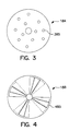
- the opening or openings in the baffle can be varied, as shown in Figs. 3, 4 and 5 and discussed below, depending upon the requirements of the given application to provide improved gas utilization and which may also include means for educing the gas into the liquid. In this manner, the gas and liquid reactants can be mixed and re-circulated without appreciable loss of gas to the headspace above the liquid level in the reaction vessel.
- the baffle may be stationarily mounted within the reaction vessel or may float on the liquid within the vessel.
- Controller 155 may be programmed to detect the drop in pressure, provide for the addition of reactive gas and re-seal the reaction vessel.
- the controller may be programmed such that the gas is provided on demand due to the pressure of the vessel dropping below a predetermined threshold.
- the controller could also provide the inert gas on demand as needed during the course of the reaction. Controllers of this type are well known in the art and easily adapted to the task at hand.
- the reaction vessel Upon substantial completion of the reaction, the reaction vessel is vented preferably into a holding tank for subsequent treatment of the waste gas. Given the high utilization of the reactive gas during the reaction, there typically would be an insignificant amount of reactive gas vented. Such low levels of the waste gas may permit accumulation of the waste gas for more economical waste treatment. The reduction in mist formation by using baffle also reduces the amount of solvent vapor in the waste gas.
- reactor 200 as illustrated in Fig. 2, comprises a reaction vessel 220 is filled with a liquid 210.
- a baffle 218 is disposed within reaction vessel 220 such that upon filling the reaction vessel 220 with a liquid 210, a reaction zone 215 is formed below baffle 218 and a quiescent portion 213 of liquid, if any, is formed above baffle 218.
- Baffle 218 may be positioned below the liquid-gas interface 222 as shown in Fig. 2 or baffle 218 may float on liquid 210 as shown in Fig. 1.
- Headspace 225 may be sparged with nitrogen or another inert gas to provide an inert atmosphere during the reaction process.
- One or more inlet/outlets 230 are provided to access reaction vessel 220 which may also provide a means for introducing the gas and the liquid into reaction vessel 220.
- Agitator 233 is employed to cause re-circulation of liquid 210 within reaction zone 220.
- the baffle 218 inhibits mist formation of liquid 210 in headspace 225 when engaging agitator 233.
- Agitator 233 has a hollow shaft 235 connected at one end to a suitable driving means (not shown) and at the other end with impeller means 238 which are preferably adapted to cause a downward vertical flow pattern of liquid 210.
- Fig. 2 incorporates the use of eductor tubes 250 to react substantially all of reactive gas 240 with liquid 210.
- Inlet 236 is incorporated into hollow shaft 235 such that the baffled system of the present invention may better educt gas 240 which has escaped into headspace 225.
- Eductor tubes 250 extend horizontally into reaction zone 215 of liquid 210 from shaft 235.
- Shaft 235 has an inlet 236 located above the liquid-gas interface 222 with accessibility to headspace 225 through inlet 236.
- the eductor tubes 250 may have a length up to just smaller than the diameter of reaction vessel 220 and are preferably located just above impellers 238.
- Eductor tubes of varying cross-section may be positioned along shaft 235.
- impellers 238 By engaging agitator 233, impellers 238 create a downward vortex of the liquid and the gas bubbles 240 within reaction zone 215.
- the suction created by impellers 238 draws any gas in headspace 225 toward shaft 235, into eductor tubes 250 and into the reaction zone 215 as shown by the arrows in Fig. 2.
- the eductor tubes be placed in a high agitation region to maximize suction.
- any gas 240 which may escape into headspace 225 is recirculated into reaction zone 215 through eductor tubes 250.
- reaction vessel 220 is filled with a desired amount of liquid.
- a reactive gas 240 may be introduced into reaction vessel 220 by an inlet located either below the liquid-gas interface 222, preferably bubbled into the reaction zone 215, or sparged into headspace 225.
- reaction vessel 220 is substantially closed and sealed from the surrounding environment resulting in a true batch process where neither the liquid nor the gas is allowed to escape. It is important for the level of liquid 210 to be above inlet 236 to maximize the re-circulation of reactive gas 240.
- the reactive gas is substantially consumed. This results in a drop in pressure within the substantially closed reaction vessel.
- An additional amount of gas may be manually added to reaction vessel at this point.
- a controller 255 may be provided which detects the drop in pressure, provides for an additional amount of the reactive gas to be inserted into the reaction vessel and the vessel is sealed again.
- the controller may be programmed such that the gas is provided on demand due to the pressure of the vessel dropping below a predetermined threshold.
- the controller could also provide the inert gas as needed during the course of the reaction.
- the baffle utilized in the reactor of the present may float atop the liquid or may be fixed adjacent the top of the liquid level.
- the baffle has a series of apertures incorporated therein. These apertures allow any by-product gas formed by the reaction and any unreacted gas to escape from the reaction zone into the headspace. Any unreacted gas would bubble back up to the headspace through the baffle apertures and re-ingested into the reaction zone by the suctioning created during agitation.
- the reactive gas which has escaped into the headspace 125 would be drawn back into liquid 110 by the suctioning created by the downward vortex of agitator 133.
- the reactive gas is drawn through hollow shaft 235 and back into the reaction zone 215 through eductor tubes 250.
- Fig. 3 illustrates a preferred embodiment of a baffle 18A which maybe used to practice the present invention.
- Baffle 18A has a series of apertures 385, although only a single aperture, e.g. annular shaped baffle, may be utilized as in Fig. 1.
- baffle 18A floats on the surface of the liquid within a reaction vessel such that a varying liquid level may be accommodated.
- Fig. 4 illustrates a baffle 18B comprising two layers, the layer below shown in phantom lines, disposed over each other. Upon sliding rotation of the two layers, the apertures 485 may vary in size.
- Fig. 5 illustrates yet another embodiment, baffle 18C, wherein the apertures comprise concentric openings 505 with aperture 510 providing an opening for the impeller shaft.
- the baffle is also adapted to reduce the formation of mist in the headspace of the reaction vessel during agitation of the liquid.
- the reduction of mist in the headspace decreases the likelihood of explosion for a flammable or reactive liquid/gas combination such as an organic liquid with oxygen particularly where the flash point of the liquid is above the operating temperature of the reaction.
- a flammable or reactive liquid/gas combination such as an organic liquid with oxygen particularly where the flash point of the liquid is above the operating temperature of the reaction.
- the mist is the only explosion risk.
- the vapor concentration may become flammable even without a mist.
- the explosion risk is further increased when using a highly explosive gas such as oxygen or hydrogen.
- the reduction in mist formation by the baffle in the headspace decreases the need for providing an inert atmosphere with a gas, such as nitrogen, in the headspace while also decreasing the amount of reactive gas which may escape into the headspace.
- typical gases include air, oxygen, hydrogen, hydrogen halides, carbon monoxide, carbon dioxide, ammonia, bromine, chlorine, iodine, fluorine, steam, water vapor, oxides of nitrogen, oxides of sulfur, and mixtures thereof.
- oxygen rather than air when practicing the instant invention.
- the high gas utilization of the present invention substantially reduces any explosion risk since mist formation is suppressed and very little oxygen remains in the headspace or may be inerted with a relatively small volume of inert gas such as nitrogen.
- an inert atmosphere may be created in the headspace by purging and filling with an inert gas such as nitrogen, argon or helium.
- the present invention allows very little, if any, gas to escape to the headspace, only a small amount of inert gas would be required.
- the apparatus could be run without an inert gas purge if the liquid vapor pressure were below the explosion limit.
- the baffle may not be necessary where mist explosions are prevented by the amount of inert gas present in the headspace.
- the inert gas could also be provided on an as-needed basis during the course of the reaction.
- the reactive gas is substantially consumed. This results in a drop in pressure within the substantially closed reaction vessel.
- An additional amount of gas may be manually added to reaction vessel at this point.
- a controller 255 may be provided which detects the drop in pressure, provides for an additional amount of the reactive gas to be inserted into the reaction vessel and the vessel is sealed again.
- the controller may be programmed such that the gas is provided on demand due to the pressure of the vessel dropping below a predetermined threshold.
- the controller could also provide the inert gas as needed during the course of the reaction.
- the reaction vessel Upon substantial completion of the reaction, the reaction vessel is vented preferably into a holding tank for subsequent treatment of the waste gas. Given the high utilization of the reactive gas during the reaction, there typically would be an insignificant amount of reactive gas vented. Again, such low levels of the waste gas may permit accumulation of the waste gas for more economical waste treatment.
- the reduction in mist formation by using the baffle also reduces the amount of solvent vapor in the waste gas.
- the present invention achieves the objects recited above.
- the process of the present invention provides a method of utilizing substantially all of the reactive gas in a liquid-gas reaction such that continuous venting is unnecessary.
- the absence of the need for continuous venting allows more economical waste treatment since there is little unreacted gas remaining in the reaction vessel.
- the apparatus of the present invention employs a combination of eductor tubes incorporated with the hollow shaft of the impeller along with a baffle having one or more apertures to provide an increase in the re-circulation of the gas used in a liquid-gas reaction.
Landscapes
- Chemical & Material Sciences (AREA)
- Chemical Kinetics & Catalysis (AREA)
- Organic Chemistry (AREA)
- Dispersion Chemistry (AREA)
- Health & Medical Sciences (AREA)
- General Health & Medical Sciences (AREA)
- Toxicology (AREA)
- Physical Or Chemical Processes And Apparatus (AREA)
Applications Claiming Priority (2)
| Application Number | Priority Date | Filing Date | Title |
|---|---|---|---|
| US44151699A | 1999-11-17 | 1999-11-17 | |
| US441516 | 1999-11-17 |
Publications (2)
| Publication Number | Publication Date |
|---|---|
| EP1101526A2 true EP1101526A2 (fr) | 2001-05-23 |
| EP1101526A3 EP1101526A3 (fr) | 2001-10-10 |
Family
ID=23753178
Family Applications (1)
| Application Number | Title | Priority Date | Filing Date |
|---|---|---|---|
| EP00125025A Withdrawn EP1101526A3 (fr) | 1999-11-17 | 2000-11-16 | Réacteur à fonctionnement discontinu avec alimentation de gaz réactifs sur demande |
Country Status (6)
| Country | Link |
|---|---|
| EP (1) | EP1101526A3 (fr) |
| KR (1) | KR20010051733A (fr) |
| CN (1) | CN1300639A (fr) |
| BR (1) | BR0005415A (fr) |
| CA (1) | CA2326586A1 (fr) |
| MX (1) | MXPA00011275A (fr) |
Cited By (7)
| Publication number | Priority date | Publication date | Assignee | Title |
|---|---|---|---|---|
| WO2005061091A1 (fr) * | 2003-12-24 | 2005-07-07 | Roger Kennedy | Appareil pour reactions chimiques ou biologiques |
| CN106422985A (zh) * | 2016-11-30 | 2017-02-22 | 南京睿宇物联网科技有限公司 | 用于安全添加叔丁基锂至反应器的反应系统 |
| EP3122445A4 (fr) * | 2014-03-27 | 2018-01-03 | Turbulent Technologies Ltd. | Procédé et appareil de réduction de l'ingestion d'air pendant un mélange |
| CN114307917A (zh) * | 2020-09-30 | 2022-04-12 | 张家港清澄纳米科技有限公司 | 一种粉体反应釜 |
| CN115569625A (zh) * | 2022-10-27 | 2023-01-06 | 云南云天化股份有限公司 | 一种烷基磷酸酯低聚物制备装置 |
| CN116474577A (zh) * | 2023-06-11 | 2023-07-25 | 南通宏申化工有限公司 | 一种复合抗静电剂制备用气液混合装置 |
| CN118772360A (zh) * | 2024-06-24 | 2024-10-15 | 恒光新材料(江苏)股份有限公司 | 一种低voc聚氨酯原料的制备工艺及装置 |
Families Citing this family (2)
| Publication number | Priority date | Publication date | Assignee | Title |
|---|---|---|---|---|
| CN103307901A (zh) * | 2012-03-15 | 2013-09-18 | 北京有色金属研究总院 | 一种熔体扰动隔离器装置及其使用方法 |
| CN109603693B (zh) * | 2019-01-08 | 2021-01-12 | 北京化工大学 | 一种多相反应装置及系统 |
Family Cites Families (9)
| Publication number | Priority date | Publication date | Assignee | Title |
|---|---|---|---|---|
| US2557564A (en) * | 1947-03-10 | 1951-06-19 | Short Milling Co J | Oxidation of fatty matter |
| DE2255701C3 (de) * | 1972-11-14 | 1981-06-19 | Hoechst Ag, 6230 Frankfurt | Verfahren zur Herstellung sekundärer aliphatischer Amine |
| US4150900A (en) * | 1977-09-30 | 1979-04-24 | Exxon Research & Engineering Co. | Slurry mixer |
| EP0027911B1 (fr) * | 1979-10-02 | 1984-06-27 | Union Carbide Corporation | Appareil pour mettre en contact un liquide avec un gaz |
| DE3516133A1 (de) * | 1985-05-04 | 1986-11-06 | W.C. Heraeus Gmbh, 6450 Hanau | Hohlruehrer und seine verwendung |
| JPS63178833A (ja) * | 1986-10-21 | 1988-07-22 | ユニオン・カーバイド・コーポレーション | 液体内へガスを導入するための方法及び装置 |
| US4919849A (en) * | 1988-12-23 | 1990-04-24 | Union Carbide Industrial Gases Technology Corporation | Gas-liquid mixing process and apparatus |
| US5451349A (en) * | 1994-08-08 | 1995-09-19 | Praxair Technology, Inc. | Advanced gas control in gas-liquid mixing systems |
| US5856533A (en) * | 1995-12-28 | 1999-01-05 | Praxair Technology, Inc. | High efficiency heat and mass transfer for vapor phase heterogeneous reactions |
-
2000
- 2000-11-16 KR KR1020000067993A patent/KR20010051733A/ko not_active Withdrawn
- 2000-11-16 CA CA002326586A patent/CA2326586A1/fr not_active Abandoned
- 2000-11-16 CN CN00128470A patent/CN1300639A/zh active Pending
- 2000-11-16 BR BR0005415-1A patent/BR0005415A/pt not_active Application Discontinuation
- 2000-11-16 MX MXPA00011275A patent/MXPA00011275A/es unknown
- 2000-11-16 EP EP00125025A patent/EP1101526A3/fr not_active Withdrawn
Cited By (9)
| Publication number | Priority date | Publication date | Assignee | Title |
|---|---|---|---|---|
| WO2005061091A1 (fr) * | 2003-12-24 | 2005-07-07 | Roger Kennedy | Appareil pour reactions chimiques ou biologiques |
| US7887763B2 (en) | 2003-12-24 | 2011-02-15 | Roger Kennedy | Apparatus for chemical or biological reactions |
| EP3122445A4 (fr) * | 2014-03-27 | 2018-01-03 | Turbulent Technologies Ltd. | Procédé et appareil de réduction de l'ingestion d'air pendant un mélange |
| CN106422985A (zh) * | 2016-11-30 | 2017-02-22 | 南京睿宇物联网科技有限公司 | 用于安全添加叔丁基锂至反应器的反应系统 |
| CN114307917A (zh) * | 2020-09-30 | 2022-04-12 | 张家港清澄纳米科技有限公司 | 一种粉体反应釜 |
| CN115569625A (zh) * | 2022-10-27 | 2023-01-06 | 云南云天化股份有限公司 | 一种烷基磷酸酯低聚物制备装置 |
| CN116474577A (zh) * | 2023-06-11 | 2023-07-25 | 南通宏申化工有限公司 | 一种复合抗静电剂制备用气液混合装置 |
| CN116474577B (zh) * | 2023-06-11 | 2023-11-21 | 南通宏申化工有限公司 | 一种复合抗静电剂制备用气液混合装置 |
| CN118772360A (zh) * | 2024-06-24 | 2024-10-15 | 恒光新材料(江苏)股份有限公司 | 一种低voc聚氨酯原料的制备工艺及装置 |
Also Published As
| Publication number | Publication date |
|---|---|
| BR0005415A (pt) | 2001-08-07 |
| EP1101526A3 (fr) | 2001-10-10 |
| CA2326586A1 (fr) | 2001-05-17 |
| MXPA00011275A (es) | 2002-05-23 |
| CN1300639A (zh) | 2001-06-27 |
| KR20010051733A (ko) | 2001-06-25 |
Similar Documents
| Publication | Publication Date | Title |
|---|---|---|
| KR100225199B1 (ko) | 기체 제어로 인한 기체-액체 혼합 시스템 | |
| US4900480A (en) | Gas-liquid mixing | |
| CA2292113C (fr) | Dissolution de gaz amelioree | |
| EP0264905B1 (fr) | Procédé et dispositif pour mélanger des gazes et des liquides | |
| US5536875A (en) | Enhanced oxidation of organic chemicals | |
| EP0851836B1 (fr) | Procede d'extraction de l'hydrogene sulfure du soufre liquide par degazage a haute pression | |
| JP3100309B2 (ja) | 蒸発冷却を用いたテレフタル酸製造 | |
| CA2133365C (fr) | Preparation d'acide terephtalique | |
| US9586821B2 (en) | Sulfur degasser apparatus and method | |
| US6368381B1 (en) | Autoclave using agitator and sparge tube to provide high oxygen transfer rate to metal-containing solutions | |
| EP0583509B1 (fr) | Dissolution augmentée de gaz | |
| JPH11511430A (ja) | 硫黄を脱気するための方法および装置 | |
| EP1101526A2 (fr) | Réacteur à fonctionnement discontinu avec alimentation de gaz réactifs sur demande | |
| AU1860099A (en) | Autoclave having high oxygen transfer rate to metal-containing solutions | |
| JP2018512360A (ja) | 液体硫黄中の硫化水素の高効率脱気方法 | |
| EP0717720A1 (fr) | Degazage du soufre liquide | |
| US3953326A (en) | Oxygen aeration system for contaminated liquids | |
| AU740348B2 (en) | Biochemical oxidation system and process | |
| US20050260121A1 (en) | Method and apparatus for degassing liquid sulfur | |
| AU4382700A (en) | Autoclave using agitator and sparge tube to provide highgen oxygen transfer rate to metal-containing solutions |
Legal Events
| Date | Code | Title | Description |
|---|---|---|---|
| PUAI | Public reference made under article 153(3) epc to a published international application that has entered the european phase |
Free format text: ORIGINAL CODE: 0009012 |
|
| AK | Designated contracting states |
Kind code of ref document: A2 Designated state(s): AT BE CH CY DE DK ES FI FR GB GR IE IT LI LU MC NL PT SE TR |
|
| AX | Request for extension of the european patent |
Free format text: AL;LT;LV;MK;RO;SI |
|
| PUAL | Search report despatched |
Free format text: ORIGINAL CODE: 0009013 |
|
| AK | Designated contracting states |
Kind code of ref document: A3 Designated state(s): AT BE CH CY DE DK ES FI FR GB GR IE IT LI LU MC NL PT SE TR |
|
| AX | Request for extension of the european patent |
Free format text: AL;LT;LV;MK;RO;SI |
|
| RIC1 | Information provided on ipc code assigned before grant |
Free format text: 7B 01J 10/00 A, 7B 01J 19/18 B, 7B 01J 19/14 B, 7B 01J 4/00 B, 7B 01F 3/04 B |
|
| 17P | Request for examination filed |
Effective date: 20011022 |
|
| STAA | Information on the status of an ep patent application or granted ep patent |
Free format text: STATUS: THE APPLICATION HAS BEEN WITHDRAWN |
|
| 18W | Application withdrawn |
Withdrawal date: 20020328 |