EP1101537B1 - Beschichtungsvorrichtung, insbesondere für thermoplastisches Material - Google Patents
Beschichtungsvorrichtung, insbesondere für thermoplastisches Material Download PDFInfo
- Publication number
- EP1101537B1 EP1101537B1 EP00123500A EP00123500A EP1101537B1 EP 1101537 B1 EP1101537 B1 EP 1101537B1 EP 00123500 A EP00123500 A EP 00123500A EP 00123500 A EP00123500 A EP 00123500A EP 1101537 B1 EP1101537 B1 EP 1101537B1
- Authority
- EP
- European Patent Office
- Prior art keywords
- duct
- head according
- advantageously
- clamping block
- thermoplastic material
- Prior art date
- Legal status (The legal status is an assumption and is not a legal conclusion. Google has not performed a legal analysis and makes no representation as to the accuracy of the status listed.)
- Expired - Lifetime
Links
Images


Classifications
-
- B—PERFORMING OPERATIONS; TRANSPORTING
- B05—SPRAYING OR ATOMISING IN GENERAL; APPLYING FLUENT MATERIALS TO SURFACES, IN GENERAL
- B05C—APPARATUS FOR APPLYING FLUENT MATERIALS TO SURFACES, IN GENERAL
- B05C5/00—Apparatus in which liquid or other fluent material is projected, poured or allowed to flow on to the surface of the work
- B05C5/02—Apparatus in which liquid or other fluent material is projected, poured or allowed to flow on to the surface of the work the liquid or other fluent material being discharged through an outlet orifice by pressure, e.g. from an outlet device in contact or almost in contact, with the work
- B05C5/0254—Coating heads with slot-shaped outlet
- B05C5/0258—Coating heads with slot-shaped outlet flow controlled, e.g. by a valve
-
- B—PERFORMING OPERATIONS; TRANSPORTING
- B05—SPRAYING OR ATOMISING IN GENERAL; APPLYING FLUENT MATERIALS TO SURFACES, IN GENERAL
- B05C—APPARATUS FOR APPLYING FLUENT MATERIALS TO SURFACES, IN GENERAL
- B05C5/00—Apparatus in which liquid or other fluent material is projected, poured or allowed to flow on to the surface of the work
- B05C5/02—Apparatus in which liquid or other fluent material is projected, poured or allowed to flow on to the surface of the work the liquid or other fluent material being discharged through an outlet orifice by pressure, e.g. from an outlet device in contact or almost in contact, with the work
- B05C5/0254—Coating heads with slot-shaped outlet
-
- B—PERFORMING OPERATIONS; TRANSPORTING
- B29—WORKING OF PLASTICS; WORKING OF SUBSTANCES IN A PLASTIC STATE IN GENERAL
- B29C—SHAPING OR JOINING OF PLASTICS; SHAPING OF MATERIAL IN A PLASTIC STATE, NOT OTHERWISE PROVIDED FOR; AFTER-TREATMENT OF THE SHAPED PRODUCTS, e.g. REPAIRING
- B29C48/00—Extrusion moulding, i.e. expressing the moulding material through a die or nozzle which imparts the desired form; Apparatus therefor
- B29C48/03—Extrusion moulding, i.e. expressing the moulding material through a die or nozzle which imparts the desired form; Apparatus therefor characterised by the shape of the extruded material at extrusion
- B29C48/07—Flat, e.g. panels
- B29C48/08—Flat, e.g. panels flexible, e.g. films
-
- B—PERFORMING OPERATIONS; TRANSPORTING
- B29—WORKING OF PLASTICS; WORKING OF SUBSTANCES IN A PLASTIC STATE IN GENERAL
- B29C—SHAPING OR JOINING OF PLASTICS; SHAPING OF MATERIAL IN A PLASTIC STATE, NOT OTHERWISE PROVIDED FOR; AFTER-TREATMENT OF THE SHAPED PRODUCTS, e.g. REPAIRING
- B29C48/00—Extrusion moulding, i.e. expressing the moulding material through a die or nozzle which imparts the desired form; Apparatus therefor
- B29C48/25—Component parts, details or accessories; Auxiliary operations
- B29C48/256—Exchangeable extruder parts
- B29C48/2562—Mounting or handling of the die
-
- B—PERFORMING OPERATIONS; TRANSPORTING
- B29—WORKING OF PLASTICS; WORKING OF SUBSTANCES IN A PLASTIC STATE IN GENERAL
- B29C—SHAPING OR JOINING OF PLASTICS; SHAPING OF MATERIAL IN A PLASTIC STATE, NOT OTHERWISE PROVIDED FOR; AFTER-TREATMENT OF THE SHAPED PRODUCTS, e.g. REPAIRING
- B29C48/00—Extrusion moulding, i.e. expressing the moulding material through a die or nozzle which imparts the desired form; Apparatus therefor
- B29C48/25—Component parts, details or accessories; Auxiliary operations
- B29C48/30—Extrusion nozzles or dies
- B29C48/305—Extrusion nozzles or dies having a wide opening, e.g. for forming sheets
-
- B—PERFORMING OPERATIONS; TRANSPORTING
- B05—SPRAYING OR ATOMISING IN GENERAL; APPLYING FLUENT MATERIALS TO SURFACES, IN GENERAL
- B05C—APPARATUS FOR APPLYING FLUENT MATERIALS TO SURFACES, IN GENERAL
- B05C11/00—Component parts, details or accessories not specifically provided for in groups B05C1/00 - B05C9/00
- B05C11/10—Storage, supply or control of liquid or other fluent material; Recovery of excess liquid or other fluent material
-
- B—PERFORMING OPERATIONS; TRANSPORTING
- B29—WORKING OF PLASTICS; WORKING OF SUBSTANCES IN A PLASTIC STATE IN GENERAL
- B29C—SHAPING OR JOINING OF PLASTICS; SHAPING OF MATERIAL IN A PLASTIC STATE, NOT OTHERWISE PROVIDED FOR; AFTER-TREATMENT OF THE SHAPED PRODUCTS, e.g. REPAIRING
- B29C48/00—Extrusion moulding, i.e. expressing the moulding material through a die or nozzle which imparts the desired form; Apparatus therefor
- B29C48/03—Extrusion moulding, i.e. expressing the moulding material through a die or nozzle which imparts the desired form; Apparatus therefor characterised by the shape of the extruded material at extrusion
- B29C48/07—Flat, e.g. panels
Definitions
- the present invention relates to a spreading head, particularly for spreading thermoplastic material on a blank (see, for example, EP-A-0 539 971, corresponding to the preambles of claims 1 and 2).
- the head is usually composed of a lamination unit which has a beak-shaped cross-section and an upper clamping block, both not shown in the figures, and an underlying lower clamping block, designated by the reference numeral 1.
- the lower clamping block 1 there can be a single device which performs the functions of the lamination unit and of the upper clamping block.
- thermoplastic material for example adhesives including those known as “hot-melt” or “reactive hot melt” adhesives
- adhesives including those known as "hot-melt” or “reactive hot melt” adhesives
- the thermoplastic material is melted beforehand by means of an adapted continuous melting unit or a drum unloader and is then injected into the spreading head by means of gear pumps, not shown.
- Transverse distribution of the adhesive is performed by means of a closed duct 2, controlled at regularly spaced positions by valves, designated by the reference numeral 3, which determine the passage of the adhesive to a second lamination region, through channels 4, and optionally to a third region.
- Channels 4 convey the adhesive directly to the lamination unit, which is directly connected to the blank.
- the problem of cleaning is very important for the optimum operation of the head, since there can be many contamination factors, including: the accidental penetration of external agents which block one or more of the channels 4 that branch out toward the subsequent stages; mixing of different products which are chemically incompatible, triggering polymerization phenomena and consequent blockage of the channels 4; carbonization of the thermoplastic materials used, with a consequent "flue effect”; strong adhesion of the thermoplastic materials to the walls of the duct 2 and of the channels 4, consequently blocking and/or reducing their cross-sections; irreversible polymerization of water-reactive polymers.
- Partial blockage of the duct 2 or of some channels 4 of the head can in fact occur, consequently producing uneven dispensing over the entire adhesive application opening, or some channels 4 can become fully blocked, consequently failing to dispense the adhesive in some regions of the section.
- EP-A-0 539 971 discloses a dispenser which does not contact the substrate wherein the beads of viscous liquid can be dispensed intermittently without the escape of adhesive in string or strand form from the discharge outlet of the nozzle tips when the flow of adhesive is intermittently interrupted.
- thermoplastic material Another drawback of conventional spreading machines is the lack of uniform transverse distribution of the thermoplastic material, caused by the unevenness of the pressures in the channels 4, particularly in very wide heads.
- an external flow equalization device also known as manifold, which consists of a reservoir arranged upstream of the head and connected thereto by means of heated pipes, each of which is fed by a gear pump.
- the aim of the present invention is to solve the above-cited problems, eliminating the drawbacks of the cited prior art, by providing a spreading head which allows to obtain a head which can be easily accessed for cleaning, said head further allowing optimum transverse distribution of the thermoplastic material.
- an object of the present invention is to provide a spreading head which does not require additional use of other machines, such as further pumps or auxiliary reservoirs.
- Another object of the present invention is to provide a spreading head which is structurally simple and has low manufacturing costs.
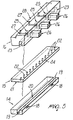
- the reference numeral 10 designates a spreading head, particularly for spreading thermoplastic material on blanks.
- the head 10 is preferably arranged transversely to the direction of travel of the blanks on which it is necessary to apply, for example, the adhesive, and has a lamination unit 11, an upper clamping block 12 and a lower clamping block, designated by the reference numeral 13.
- the lower clamping block 13 is constituted by a first element, designated by the reference numeral 14 and arranged in a downward region, which advantageously has a rectangular or trapezoidal cross-section and lies transversely to the direction of travel of the blanks.
- a second element 15 is superimposed on the first element 14 and has a lateral surface which preferably mates with the lateral surface of the first element 14.
- a third element is arranged above the second element 15 and also has a lateral surface which advantageously mates with the lateral surface of the second element 15 and can be associated above the lamination unit 11 and the upper clamping block 12.
- the first element 14, the second element 15 and the third element 16 can be detachably secured to each other by virtue of appropriate mechanical connection means, advantageously constituted by a plurality of screws, not shown in the figure, which can be arranged in adapted through holes formed in the first element 14 and the second element 15 and respectively designated by the reference numerals 17a and 17b.
- the through holes 17a and 17b are formed along an axis which is perpendicular to the axis along which lamination of the adhesive on said blanks occurs, and are connected to appropriate complementarily threaded blind holes 17c formed in said third element 16 and adapted to rigidly couple said screws.
- the first element 14 has, on its lateral surface, one or more rear inlets 18; in this embodiment there are two rear inlets, and possibly two other lateral inlets, designated by the reference numeral 19, which allow the entry of the adhesive into a first longitudinal duct 20 of the head 10.
- the first duct 20, advantageously having a rectangular cross-section, is formed in the upper surface of said first element 14 and is closed in an upward region, when the lower clamping block 13 is assembled, by a first lower surface, designated by the reference numeral 21, of the second element 15.
- the first lower surface 21 has, at said first duct 20, a plurality of first through channels, designated by the reference numeral 22, which are arranged vertically and advantageously have a narrower rectangular cross-section so as to allow a first lamination of the adhesive.
- the first channels 22 are connected, in an upward region, to a second duct, designated by the reference numeral 23, which is formed longitudinally on the lower surface of the third element 16 and is appropriately arranged above the first duct 20 and parallel thereto.
- the second duct 23, which also advantageously has a rectangular cross-section, is closed, in a downward region, once the lower clamping block 13 is assembled, by a second upper surface 24 of said second element 15.
- said third element 16 has, at appropriately regular intervals, a series of chambers 25 which are advantageously shaped like a parallelepiped and are adapted to accommodate respective complementarily shaped valves, designated by the reference numeral 26, which can be activated by horizontal translatory motion thereof at right angles to the second duct 23.
- thermoplastic material for example an adhesive
- the thermoplastic material to be spread on the blanks enters the head 10 through one or more of the rear inlets 18 and lateral inlets 19.
- Said inlets convey the adhesive into a first duct 20 which is formed in the first element 14 of the lower clamping block 13 of the head 10.
- the first duct 20 by being connected to a second duct 23 through the first channels 22 of said second element 15, sends the adhesive to the chambers 25.
- the second element 15, which constitutes a perforated plate to be interposed between the two longitudinal ducts, is meant to achieve more uniform dispensing in a transverse direction by balancing the pressures of the adhesive inside the ducts.
- the flow of adhesive to the lamination unit 11 is limited to the intended width by acting on the valves 26 so as to disconnect the unnecessary second channels 27.
- valves 26 The translatory motion of the valves 26 in a horizontal direction inside the head 10 causes said valves 26 to close the respective chambers 25.
- the deactivated valves allow the adhesive to enter the respective second channels 27 and reach, from there, the lamination unit 11.
- a head 1 having been provided which has a lower clamping block 13 which is constituted by a first element, a second element and a third element which are superimposed and can be easily inspected for cleaning.
- the presence of the second element 15 leads to better pressure balancing and therefore to more uniform dispensing in a transverse direction.
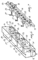
- a lower clamping block 113 is constituted by a first element, designated by the reference numeral 114 and arranged in the rear part, which has an advantageously rectangular cross-section and lies transversely to the direction of travel of the blanks.
- a second element designated by the reference numeral 115, is superimposed in front of said first element 114.
- a third element 116 is arranged in front of said second element 115, which is interposed between said first element 114 and said third element 116, having a lateral surface which advantageously mates with the lateral surfaces of said first and third elements, said third element 116 being associable, in an upward region, with a lamination unit 111 and with an upper clamping block, designated by the reference numeral 112.
- the first element 114, the second element 115 and the third element 116 can be detachably secured to each other by virtue of appropriate mechanical connection means, advantageously constituted by a plurality of screws, not shown, which are arranged on an axis which is approximately parallel to the axis along which the thermoplastic material, for example an adhesive, is laminated onto said blanks.
- Said screws can be arranged in appropriate through holes which are formed in said first element 114 and said second element 115 and are designated by the reference numerals 117a and 117b respectively; said screws can further be rigidly coupled in appropriate complementarily threaded blind holes 117c formed in said third element 116.
- the third element 116 has, on its lower surface, one or more inlets 118; this embodiment shows a single inlet, which allows the inflow of the adhesive into a first longitudinal duct 120 of the head 110.
- the first duct 120 which advantageously has a rectangular cross-section, is formed in the rear surface of the third element 116 and is laterally closed, when the lower clamping block 113 is assembled, by a first front surface, designated by the reference numeral 121, of the second element 115.
- the first front surface 121 has, at first duct 120, a plurality of first through channels which are mutually identical, are arranged on a same horizontal plane and are designated by the reference numeral 122; the channels have an advantageously narrower rectangular cross-section so as to allow a first lamination of the adhesive.
- the first channels 122 are connected, in a rear region, to a second duct, designated by the reference numeral 123, which is formed in the front surface of the first element 114 along a longitudinal direction and is conveniently arranged to the rear of, and parallel to, the first duct 120.
- the second duct 123 which also advantageously has a rectangular cross-section, is closed at the front, when the lower clamping block 113 is assembled, by a second rear surface 124 of the second element 115.
- the first element 114 has, at appropriately regular intervals, a series of chambers 125 which are advantageously shaped like a parallelepiped and are adapted to accommodate respective complementarily shaped valves, designated by the reference numeral 126, which can be activated by way of their horizontal translatory motion at right angles to the second duct 123.
- valves 126 are advantageously arranged alternately on staggered planes, so that one is connected in an upward region to the second duct 123 and the other one is connected thereto in a downward region.
- the second channel 127a is connected to a third channel 127b which is formed in the third element 116 and is inclined upward or downward according to the position of the respective chamber 125; the third channel is connected to a fourth channel 127c which is advantageously vertical.
- the fourth channel 127c ends at a third upper surface, designated by the reference numeral 128, of the third element 116 which is associable with a respective surface of the lamination unit 111.
- thermoplastic material for example an adhesive
- the useful width of this type of machine varies, according to the width of the blanks, in a discrete manner with a spacing between one width and the next which is proportional to the dimensions of the valves used.
- the advantage of this second embodiment consists of the fact that it is possible to reduce the spacing between one useful width and the next, since the valves are arranged in a staggered and superimposed configuration.
- valves measuring approximately 30 mm which accordingly entails, in the first embodiment, a spacing of approximately 100 mm between one valve and the next, in the variation described here it is possible to have a smaller spacing, down to 50 mm, with consequent better adaptability to the dimensions of the blanks.
Landscapes
- Engineering & Computer Science (AREA)
- Mechanical Engineering (AREA)
- Manufacturing & Machinery (AREA)
- Coating Apparatus (AREA)
- Extrusion Moulding Of Plastics Or The Like (AREA)
- Laminated Bodies (AREA)
- Surface Treatment Of Glass Fibres Or Filaments (AREA)
- Processing And Handling Of Plastics And Other Materials For Molding In General (AREA)
- Application Of Or Painting With Fluid Materials (AREA)
- Processes Of Treating Macromolecular Substances (AREA)
Claims (21)
- Beschichtungsvorrichtung insbesondere zum Beschichten eines Rohlings mit thermoplastischem Material, mit einem unteren Klemmblock (13, 113), einer Beschichtungseinheit (11, 111) und einem oberen Klemmblock (12, 112), der quer zu der Vorschubrichtung des Rohlings angeordnet ist, dadurch gekennzeichnet, daß der untere Klemmblock (13, 113) von einem ersten Element (14, 114) und einem dritten Element (16, 116) gebildet wird, die mittels mechanischer Verbindungsmittel lösbar miteinander verbunden werden können, wobei das erste Element (14, 114) eine erste in Längsrichtung verlaufende Leitung (20, 120) hat, die mit einer zweiten in Längsrichtung verlaufenden Leitung (23, 123) verbunden ist, die in dem dritten Element (16, 116) gebildet ist.
- Beschichtungsvorrichtung (10) insbesondere zum gleichmäßigen Beschichten eines Rohlings mit thermoplastischem Material, mit einem unteren Klemmblock (13, 113), einer Beschichtungseinheit (11, 111) und einem oberen Klemmblock (12, 112), der quer zu der Vorschubrichtung des Rohlings angeordnet ist, dadurch gekennzeichnet, daß der untere Klemmblock (13, 113) von einem ersten Element (14, 114), einem zweiten Element (15, 115) und einem dritten Element (16, 116) gebildet wird, die mittels mechanischer Verbindungsmittel gegenseitig lösbar miteinander verbunden sind, wobei das erste Element (14, 114) eine erste in Längsrichtung verlaufende Leitung (20, 120) hat, die mit einer Vielzahl von ersten Kanälen (22, 122) verbunden ist, die in dem zweiten Element (15, 115) gebildet sind, wobei die ersten Kanäle (22), die Durchgangskanäle sind und vertikal angeordnet sind, einen Querschnitt mit kleineren Abmessungen bezüglich der in Längsrichtung verlaufenden Leitung (20, 120) haben, um eine erste Schichtbildung mit dem thermoplastischen Material zu gestatten und einen Druckausgleich der Schmelzflüssigkeit in einer Querrichtung auszuführen, um eine gleichmäßige Ausbreitung des thermoplastischen Materials in einer Querrichtung zu erzielen, wobei das dritte Element (16, 116) eine zweite in Längsrichtung verlaufende Leitung (23, 123) hat, die mit den ersten Kanälen (22, 122) und einer Reihe von Kammern (25, 125) verbunden ist, wobei jede Kammer mit einem zweiten Kanal (27, 127) verbunden ist, wobei der zweite Kanal (27, 127) mit der Beschichtungseinheit (11, 111) verbunden ist, um einen Rohling mit dem thermoplastischen Material gleichmäßig zu beschichten.
- Vorrichtung nach Anspruch 2, dadurch gekennzeichnet, daß das erste Element (14) einen rechtwinkligen oder trapezförmigen Querschnitt und eine seitliche Fläche hat, die vorzugsweise mit der seitlichen Fläche des zweiten Elements (15) zusammenpaßt, das über dem ersten Element (14) angeordnet ist, wobei das dritte Element (16) über dem zweiten Element (14) angeordnet ist und auch eine seitliche Fläche hat, die vorteilhafterweise mit der seitlichen Fläche des zweiten Elements (15) zusammenpaßt.
- Vorrichtung nach Anspruch 3, dadurch gekennzeichnet, daß die mechanischen Verbindungsmittel zum gegenseitigen lösbaren Verbinden des ersten (14), zweiten (15) und dritten (16) Elements von einer Vielzahl von Schrauben gebildet werden, die in angepaßten Durchgangslöchern (17a, 17b) angeordnet sind, die in dem ersten (14) und dem zweiten (15) Element entlang einer Achse gebildet sind, die senkrecht zu der Achse ist, entlang derer die Beschichtung der Rohlinge mit dem thermoplastischen Material auftritt, wobei die Schrauben in geeigneten komplementär geformten Sacklöchern (17c), die in dem dritten Element (16) gebildet sind, starr befestigbar sind.
- Vorrichtung nach irgendeinem der vorhergehenden Ansprüche 2 bis 4, dadurch gekennzeichnet, daß das erste Element (14) einen oder mehrere Einlässe (18, 19) für das thermoplastische Material hat, wobei die Einlässe vorzugsweise auf der seitlichen Fläche in einer hinteren Position und/oder in einer seitlichen Position angeordnet sind.
- Vorrichtung nach Anspruch 5, dadurch gekennzeichnet, daß die Einlässe (18, 19) mit der ersten Leitung (20) verbunden sind, die in der oberen Fläche des ersten Elements (14) mit einem Querschnitt gebildet ist, der vorteilhafterweise rechtwinklig ist, wobei die erste Leitung (20) in einem oberen Bereich durch eine erste untere Fläche (21) des zweiten Elements (15) geschlossen wird, wenn der untere Klemmblock (13) zusammengebaut wird.
- Vorrichtung nach Anspruch 6, dadurch gekennzeichnet, daß die ersten Kanäle (22), die Durchgangskanäle sind und vertikal angeordnet sind, an der ersten unteren Fläche (21) gebildet sind und vorteilhafterweise einen rechtwinkligen Querschnitt mit kleineren Abmessungen als der rechtwinklige Querschnitt der ersten in Längsrichtung verlaufenden Leitung (20, 120) hat, um eine erste Beschichtung mit dem thermoplastischen Material zu gestatten.
- Vorrichtung nach Anspruch 7, dadurch gekennzeichnet, daß die ersten Kanäle (22) in einem oberen Bereich mit der zweiten Leitung (23) verbunden sind, die in Längsrichtung verlaufend auf der unteren Fläche (21) des dritten Elements (16) gebildet ist und in geeigneter Weise über der ersten Leitung (20) und parallel dazu angeordnet ist.
- Vorrichtung nach Anspruch 6, dadurch gekennzeichnet, daß die zweite Leitung (23), die vorteilhafterweise auch einen rechtwinkligen Querschnitt hat, in einem unteren Bereich durch eine zweite obere Fläche (24) des zweiten Elements (15) geschlossen wird, wenn der untere Klemmblock (13) zusammengebaut wird.
- Vorrichtung nach irgendeinem der vorhergehenden Ansprüche 2 bis 9, dadurch gekennzeichnet, daß bei ihr die Reihe von Kammern (25) in geeigneten regelmäßigen Abständen an der zweiten Leitung (23) entlang und über ihr angeordnet ist, wobei die Kammern (25) vorteilhafterweise wie ein Parallelepiped geformt sind und ausgebildet sind, jeweils komplementär geformte Ventile (26) aufzunehmen, die durch eine horizontale translatorische Bewegung der Ventile im rechten Winkel zu der zweiten Leitung (23) aktiviert werden können.
- Vorrichtung nach Anspruch 2, dadurch gekennzeichnet, daß ein zweiter Kanal (27) mit jeder der Kammern (25) verbunden ist, wobei der Kanal vorteilhafterweise L-förmig oder S-förmig ist und mit einer dritten oberen Fläche (28) verbunden ist, mit der eine angepaßte Fläche der Beschichtungseinheit (11) verbunden ist.
- Vorrichtung nach Anspruch 2, dadurch gekennzeichnet, daß das erste Element (114) in dem hinteren Teil des unteren Klemmblockes (113) angeordnet ist, das zweite Element (115) vor dem ersten Element (114) angeordnet ist, das dritte Element (116) vor dem zweiten Element (115) angeordnet ist, das eine seitliche Fläche hat, die vorteilhafterweise mit den seitlichen Flächen des ersten (114) und dritten (116) Elements zusammenpaßt und zwischen ihnen angeordnet ist, wobei das erste (114), zweite (115) und dritte Element (116) mittels Schrauben gegenseitig blockierbar sind, die entlang einer Achse angeordnet sind, die annähernd parallel zu der Beschichtungsachse ist.
- Vorrichtung nach Anspruch 12, dadurch gekennzeichnet, daß das dritte Element (116) vorzugsweise an seiner unteren Fläche einen oder mehrere Einlässe (118) für das thermoplastische Material hat.
- Vorrichtung nach Anspruch 13, dadurch gekennzeichnet, daß die Einlässe (118) mit der ersten Leitung (120) verbunden sind, die vorteilhafterweise einen rechtwinkligen Querschnitt hat und in Längsrichtung verlaufend angeordnet ist, wobei die erste Leitung (120) in der hinteren Fläche des dritten Elements (116) gebildet ist und durch eine erste vordere Fläche (121) des zweiten Elements (115) seitlich geschlossen wird, wenn der untere Klemmblock (113) zusammengebaut wird.
- Vorrichtung nach Anspruch 14, dadurch gekennzeichnet, daß die erste vordere Fläche (121) die Vielzahl von ersten Durchgangskanälen (122) hat, die zueinander identisch sind, auf der gleichen Horizontalebene angeordnet sind und vorteilhafterweise einen rechtwinkligen Querschnitt haben, der schmäler als der rechtwinklige Querschnitt der ersten in Längsrichtung verlaufenden Leitung (20, 120) ist, um eine erste Beschichtung mit dem thermoplastischen Material zu gestatten.
- Vorrichtung nach irgendeinem der Ansprüche 2 bis 5, dadurch gekennzeichnet, daß die ersten Kanäle (122) in einem hinteren Bereich mit der zweiten Leitung (123) verbunden sind, die in der vorderen Fläche des ersten Elements (114) in einer Längsrichtung entlang gebildet ist und vorteilhafterweise hinter der ersten Leitung (120) und parallel dazu angeordnet ist.
- Vorrichtung nach Anspruch 16, dadurch gekennzeichnet, daß die zweite Leitung (123), die auch vorteilhafterweise einen rechtwinkligen Querschnitt hat, an der Vorderseite durch eine zweite hintere Fläche (124) des zweiten Elements (115) geschlossen wird, wenn der untere Klemmblock (113) zusammengebaut wird.
- Vorrichtung nach irgendeinem der Ansprüche 12 bis 17, dadurch gekennzeichnet, daß die Reihe von Kammern (125) in geeigneten regelmäßigen Abständen angeordnet ist, wobei die Kammern (125) vorteilhafterweise wie ein Parallelepiped geformt und ausgebildet sind, um jeweilige komplementär geformte Ventile (126) aufzunehmen, die durch eine horizontale translatorische Bewegung der Ventile im rechten Winkel zu der zweiten Leitung (123) aktiviert werden können.
- Vorrichtung nach Anspruch 18, dadurch gekennzeichnet, daß die Ventile (126) vorteilhafterweise abwechselnd auf gestaffelten Ebenen angeordnet sind, so daß das eine in einem oberen Bereich mit der zweiten Leitung (123) und das andere Ventil in einem unteren Bereich damit verbunden ist.
- Vorrichtung nach Anspruch 18 oder 19, dadurch gekennzeichnet, daß ein zweiter Kanal (127a) mit jeder der Kammern (125) verbunden ist, vorteilhafterweise horizontal ist und entlang der gleichen Achse in dem ersten (114) und zweiten Element (115) gebildet ist, wobei der zweite Kanal (127a) mit einem dritten Kanal (127b) verbunden ist, der in dem dritten Element (116) gebildet ist und nach oben oder nach unten entsprechend der Position der jeweiligen Kammer (125) geneigt ist.
- Vorrichtung nach Anspruch 20, dadurch gekennzeichnet, daß der dritte Kanal (127b) mit einem vierten Kanal (127c) verbunden ist, der vorteilhafterweise vertikal ist und an einer dritten oberen Fläche (128) des dritten Elements (116) austritt, das mit einer jeweiligen Fläche der Beschichtungseinheit (111) verbindbar ist.
Applications Claiming Priority (2)
| Application Number | Priority Date | Filing Date | Title |
|---|---|---|---|
| IT1999TV000124A IT1311872B1 (it) | 1999-11-16 | 1999-11-16 | Testata di spalmatura,particolarmente per materiale termoplastico. |
| ITTV990124 | 1999-11-16 |
Publications (2)
| Publication Number | Publication Date |
|---|---|
| EP1101537A1 EP1101537A1 (de) | 2001-05-23 |
| EP1101537B1 true EP1101537B1 (de) | 2005-06-01 |
Family
ID=11420701
Family Applications (1)
| Application Number | Title | Priority Date | Filing Date |
|---|---|---|---|
| EP00123500A Expired - Lifetime EP1101537B1 (de) | 1999-11-16 | 2000-11-08 | Beschichtungsvorrichtung, insbesondere für thermoplastisches Material |
Country Status (5)
| Country | Link |
|---|---|
| EP (1) | EP1101537B1 (de) |
| AT (1) | ATE296683T1 (de) |
| DE (1) | DE60020496T2 (de) |
| ES (1) | ES2241537T3 (de) |
| IT (1) | IT1311872B1 (de) |
Families Citing this family (6)
| Publication number | Priority date | Publication date | Assignee | Title |
|---|---|---|---|---|
| IT1311872B1 (it) | 1999-11-16 | 2002-03-19 | Hip High Ind Performances Srl | Testata di spalmatura,particolarmente per materiale termoplastico. |
| ITTV20040020A1 (it) * | 2004-03-02 | 2004-06-02 | Hip Srl High Ind Performance S | Dispositivo di spalmatura, particolarmente per la deposizione di adesivi e/o materiali polimerici in dispersione liquida |
| ITTV20060124A1 (it) * | 2006-07-17 | 2008-01-18 | Hip Mitsu Srl | Struttura di testata di spalmatura, particolarmente di uno o piu' adesivi o miscele di adesivi |
| ITTV20060123A1 (it) * | 2006-07-17 | 2008-01-18 | Hip Mitsu Srl | Struttura di testata di spalmatura, particolarmente di uno o piu' adesivi o miscele di adesivi |
| DE102007052996A1 (de) * | 2007-11-05 | 2009-05-07 | Beiersdorf Ag | Beschichtungswerkzeug zum Beschichten flächiger Materialien |
| DE202010013054U1 (de) * | 2010-12-03 | 2012-03-05 | Baumer Hhs Gmbh | Vorrichtung zum Auftragen von viskosen Medien |
Family Cites Families (6)
| Publication number | Priority date | Publication date | Assignee | Title |
|---|---|---|---|---|
| US5067432A (en) * | 1990-05-23 | 1991-11-26 | Extrusion Dies, Inc. | Replaceable wiping insert for slot die head |
| CA2081499A1 (en) * | 1991-11-01 | 1993-05-02 | Wesley Fort | Method and apparatus for dispensing multiple beads of viscous liquid |
| DE59305026D1 (de) * | 1992-07-03 | 1997-02-20 | Friz Maschinenbau Gmbh | Vorrichtung zum Auftragen von Klebstoff |
| JP2932163B2 (ja) * | 1994-11-28 | 1999-08-09 | 株式会社ヒラノテクシード | 両面塗工型塗工装置 |
| US5728219A (en) * | 1995-09-22 | 1998-03-17 | J&M Laboratories, Inc. | Modular die for applying adhesives |
| IT1311872B1 (it) | 1999-11-16 | 2002-03-19 | Hip High Ind Performances Srl | Testata di spalmatura,particolarmente per materiale termoplastico. |
-
1999
- 1999-11-16 IT IT1999TV000124A patent/IT1311872B1/it active
-
2000
- 2000-11-08 DE DE60020496T patent/DE60020496T2/de not_active Expired - Lifetime
- 2000-11-08 ES ES00123500T patent/ES2241537T3/es not_active Expired - Lifetime
- 2000-11-08 AT AT00123500T patent/ATE296683T1/de not_active IP Right Cessation
- 2000-11-08 EP EP00123500A patent/EP1101537B1/de not_active Expired - Lifetime
Also Published As
| Publication number | Publication date |
|---|---|
| ES2241537T3 (es) | 2005-11-01 |
| EP1101537A1 (de) | 2001-05-23 |
| IT1311872B1 (it) | 2002-03-19 |
| ITTV990124A1 (it) | 2001-05-16 |
| ATE296683T1 (de) | 2005-06-15 |
| DE60020496D1 (de) | 2005-07-07 |
| DE60020496T2 (de) | 2005-11-10 |
Similar Documents
| Publication | Publication Date | Title |
|---|---|---|
| US5636790A (en) | Fluid applicator | |
| US5000112A (en) | Apparatus for the surface coating of glue | |
| CA1291679C (en) | Method and apparatus for applying narrow, closely spaced beads of viscous liquid to a substrate | |
| CN109641233A (zh) | 具有分流器板的涂覆器 | |
| US7152815B2 (en) | Dispensing system, nozzle and method for independently dispensing and controlling liquid | |
| EP1880773B1 (de) | Streukopf, insbesondere zur Streuung eines oder mehrerer Haftmittel oder einer oder mehrerer Haftmittelmischungen | |
| US6375099B1 (en) | Split output adhesive nozzle assembly | |
| JP5078233B2 (ja) | 個別化した処理空気制御部を有する液体ディスペンサ | |
| US5740963A (en) | Self-sealing slot nozzle die | |
| US9168539B2 (en) | Method of applying thermoplastic liquid onto a substrate | |
| EP1101537B1 (de) | Beschichtungsvorrichtung, insbesondere für thermoplastisches Material | |
| KR20060120564A (ko) | 기판 상에 유체 재료를 적층시키기 위한 장치 | |
| US20050235909A1 (en) | Angled manifold and dispensing apparatus | |
| US5851566A (en) | Applicator die | |
| US5843230A (en) | Sealing system for improved applicator die | |
| JP3338693B2 (ja) | ストライプ塗布用ダイセット、およびその方法 | |
| EP1085946B1 (de) | Verteilvorrichtung für ein fluid wie klebstoff | |
| US20010042507A1 (en) | Device for applying adhesives | |
| AU775335B2 (en) | Fluid applicator | |
| AU748546B2 (en) | Fluid applicator | |
| CA2443000A1 (en) | Method and apparatus for forming an extrusion | |
| JPH0575471B2 (de) |
Legal Events
| Date | Code | Title | Description |
|---|---|---|---|
| PUAI | Public reference made under article 153(3) epc to a published international application that has entered the european phase |
Free format text: ORIGINAL CODE: 0009012 |
|
| AK | Designated contracting states |
Kind code of ref document: A1 Designated state(s): AT BE CH CY DE DK ES FI FR GB GR IE IT LI LU MC NL PT SE TR |
|
| AX | Request for extension of the european patent |
Free format text: AL;LT;LV;MK;RO;SI |
|
| 17P | Request for examination filed |
Effective date: 20011122 |
|
| AKX | Designation fees paid |
Free format text: AT BE CH CY DE DK ES FI FR GB GR IE IT LI LU MC NL PT SE TR |
|
| 17Q | First examination report despatched |
Effective date: 20031216 |
|
| GRAP | Despatch of communication of intention to grant a patent |
Free format text: ORIGINAL CODE: EPIDOSNIGR1 |
|
| GRAS | Grant fee paid |
Free format text: ORIGINAL CODE: EPIDOSNIGR3 |
|
| GRAA | (expected) grant |
Free format text: ORIGINAL CODE: 0009210 |
|
| RAP1 | Party data changed (applicant data changed or rights of an application transferred) |
Owner name: HIP-MITSU S.R.L. |
|
| AK | Designated contracting states |
Kind code of ref document: B1 Designated state(s): AT BE CH CY DE DK ES FI FR GB GR IE IT LI LU MC NL PT SE TR |
|
| PG25 | Lapsed in a contracting state [announced via postgrant information from national office to epo] |
Ref country code: FI Free format text: LAPSE BECAUSE OF FAILURE TO SUBMIT A TRANSLATION OF THE DESCRIPTION OR TO PAY THE FEE WITHIN THE PRESCRIBED TIME-LIMIT Effective date: 20050601 Ref country code: BE Free format text: LAPSE BECAUSE OF FAILURE TO SUBMIT A TRANSLATION OF THE DESCRIPTION OR TO PAY THE FEE WITHIN THE PRESCRIBED TIME-LIMIT Effective date: 20050601 Ref country code: AT Free format text: LAPSE BECAUSE OF FAILURE TO SUBMIT A TRANSLATION OF THE DESCRIPTION OR TO PAY THE FEE WITHIN THE PRESCRIBED TIME-LIMIT Effective date: 20050601 Ref country code: TR Free format text: LAPSE BECAUSE OF FAILURE TO SUBMIT A TRANSLATION OF THE DESCRIPTION OR TO PAY THE FEE WITHIN THE PRESCRIBED TIME-LIMIT Effective date: 20050601 |
|
| REG | Reference to a national code |
Ref country code: GB Ref legal event code: FG4D |
|
| REG | Reference to a national code |
Ref country code: CH Ref legal event code: EP |
|
| REG | Reference to a national code |
Ref country code: IE Ref legal event code: FG4D |
|
| REF | Corresponds to: |
Ref document number: 60020496 Country of ref document: DE Date of ref document: 20050707 Kind code of ref document: P |
|
| REG | Reference to a national code |
Ref country code: CH Ref legal event code: NV Representative=s name: MARK-PAT MODIANO S.A. |
|
| PG25 | Lapsed in a contracting state [announced via postgrant information from national office to epo] |
Ref country code: DK Free format text: LAPSE BECAUSE OF FAILURE TO SUBMIT A TRANSLATION OF THE DESCRIPTION OR TO PAY THE FEE WITHIN THE PRESCRIBED TIME-LIMIT Effective date: 20050901 Ref country code: GR Free format text: LAPSE BECAUSE OF FAILURE TO SUBMIT A TRANSLATION OF THE DESCRIPTION OR TO PAY THE FEE WITHIN THE PRESCRIBED TIME-LIMIT Effective date: 20050901 Ref country code: SE Free format text: LAPSE BECAUSE OF FAILURE TO SUBMIT A TRANSLATION OF THE DESCRIPTION OR TO PAY THE FEE WITHIN THE PRESCRIBED TIME-LIMIT Effective date: 20050901 |
|
| REG | Reference to a national code |
Ref country code: ES Ref legal event code: FG2A Ref document number: 2241537 Country of ref document: ES Kind code of ref document: T3 |
|
| PG25 | Lapsed in a contracting state [announced via postgrant information from national office to epo] |
Ref country code: PT Free format text: LAPSE BECAUSE OF FAILURE TO SUBMIT A TRANSLATION OF THE DESCRIPTION OR TO PAY THE FEE WITHIN THE PRESCRIBED TIME-LIMIT Effective date: 20051103 |
|
| PG25 | Lapsed in a contracting state [announced via postgrant information from national office to epo] |
Ref country code: CY Free format text: LAPSE BECAUSE OF FAILURE TO SUBMIT A TRANSLATION OF THE DESCRIPTION OR TO PAY THE FEE WITHIN THE PRESCRIBED TIME-LIMIT Effective date: 20051108 Ref country code: IE Free format text: LAPSE BECAUSE OF NON-PAYMENT OF DUE FEES Effective date: 20051108 |
|
| PG25 | Lapsed in a contracting state [announced via postgrant information from national office to epo] |
Ref country code: MC Free format text: LAPSE BECAUSE OF NON-PAYMENT OF DUE FEES Effective date: 20051130 Ref country code: LU Free format text: LAPSE BECAUSE OF NON-PAYMENT OF DUE FEES Effective date: 20051130 |
|
| ET | Fr: translation filed | ||
| PLBE | No opposition filed within time limit |
Free format text: ORIGINAL CODE: 0009261 |
|
| STAA | Information on the status of an ep patent application or granted ep patent |
Free format text: STATUS: NO OPPOSITION FILED WITHIN TIME LIMIT |
|
| 26N | No opposition filed |
Effective date: 20060302 |
|
| REG | Reference to a national code |
Ref country code: IE Ref legal event code: MM4A |
|
| REG | Reference to a national code |
Ref country code: DE Ref legal event code: R082 Ref document number: 60020496 Country of ref document: DE Representative=s name: ANDRAE WESTENDORP PATENTANWAELTE PARTNERSCHAFT, DE Ref country code: DE Ref legal event code: R082 Ref document number: 60020496 Country of ref document: DE Representative=s name: SCHIEBER FARAGO PATENTANWAELTE, DE Ref country code: DE Ref legal event code: R082 Ref document number: 60020496 Country of ref document: DE Representative=s name: FARAGO PATENTANWALTS- UND RECHTSANWALTSGESELLS, DE |
|
| REG | Reference to a national code |
Ref country code: FR Ref legal event code: PLFP Year of fee payment: 16 |
|
| REG | Reference to a national code |
Ref country code: FR Ref legal event code: PLFP Year of fee payment: 17 |
|
| REG | Reference to a national code |
Ref country code: FR Ref legal event code: PLFP Year of fee payment: 18 |
|
| PGFP | Annual fee paid to national office [announced via postgrant information from national office to epo] |
Ref country code: FR Payment date: 20171031 Year of fee payment: 18 |
|
| REG | Reference to a national code |
Ref country code: DE Ref legal event code: R082 Ref document number: 60020496 Country of ref document: DE Representative=s name: SCHIEBER FARAGO PATENTANWAELTE, DE Ref country code: DE Ref legal event code: R082 Ref document number: 60020496 Country of ref document: DE Representative=s name: FARAGO PATENTANWALTS- UND RECHTSANWALTSGESELLS, DE Ref country code: DE Ref legal event code: R082 Ref document number: 60020496 Country of ref document: DE Representative=s name: FARAGO PATENTANWAELTE, DE |
|
| PGFP | Annual fee paid to national office [announced via postgrant information from national office to epo] |
Ref country code: GB Payment date: 20171123 Year of fee payment: 18 |
|
| REG | Reference to a national code |
Ref country code: DE Ref legal event code: R082 Ref document number: 60020496 Country of ref document: DE Representative=s name: FARAGO PATENTANWALTS- UND RECHTSANWALTSGESELLS, DE Ref country code: DE Ref legal event code: R082 Ref document number: 60020496 Country of ref document: DE Representative=s name: FARAGO PATENTANWAELTE, DE |
|
| PGFP | Annual fee paid to national office [announced via postgrant information from national office to epo] |
Ref country code: NL Payment date: 20181127 Year of fee payment: 19 |
|
| PGFP | Annual fee paid to national office [announced via postgrant information from national office to epo] |
Ref country code: DE Payment date: 20181123 Year of fee payment: 19 |
|
| PGFP | Annual fee paid to national office [announced via postgrant information from national office to epo] |
Ref country code: ES Payment date: 20181213 Year of fee payment: 19 Ref country code: IT Payment date: 20181116 Year of fee payment: 19 |
|
| PGFP | Annual fee paid to national office [announced via postgrant information from national office to epo] |
Ref country code: CH Payment date: 20190124 Year of fee payment: 19 |
|
| GBPC | Gb: european patent ceased through non-payment of renewal fee |
Effective date: 20181108 |
|
| PG25 | Lapsed in a contracting state [announced via postgrant information from national office to epo] |
Ref country code: FR Free format text: LAPSE BECAUSE OF NON-PAYMENT OF DUE FEES Effective date: 20181130 |
|
| PG25 | Lapsed in a contracting state [announced via postgrant information from national office to epo] |
Ref country code: GB Free format text: LAPSE BECAUSE OF NON-PAYMENT OF DUE FEES Effective date: 20181108 |
|
| REG | Reference to a national code |
Ref country code: DE Ref legal event code: R119 Ref document number: 60020496 Country of ref document: DE |
|
| REG | Reference to a national code |
Ref country code: CH Ref legal event code: PL |
|
| REG | Reference to a national code |
Ref country code: NL Ref legal event code: MM Effective date: 20191201 |
|
| PG25 | Lapsed in a contracting state [announced via postgrant information from national office to epo] |
Ref country code: CH Free format text: LAPSE BECAUSE OF NON-PAYMENT OF DUE FEES Effective date: 20191130 Ref country code: LI Free format text: LAPSE BECAUSE OF NON-PAYMENT OF DUE FEES Effective date: 20191130 |
|
| PG25 | Lapsed in a contracting state [announced via postgrant information from national office to epo] |
Ref country code: NL Free format text: LAPSE BECAUSE OF NON-PAYMENT OF DUE FEES Effective date: 20191201 |
|
| PG25 | Lapsed in a contracting state [announced via postgrant information from national office to epo] |
Ref country code: IT Free format text: LAPSE BECAUSE OF NON-PAYMENT OF DUE FEES Effective date: 20191108 Ref country code: DE Free format text: LAPSE BECAUSE OF NON-PAYMENT OF DUE FEES Effective date: 20200603 |
|
| REG | Reference to a national code |
Ref country code: ES Ref legal event code: FD2A Effective date: 20210414 |
|
| PG25 | Lapsed in a contracting state [announced via postgrant information from national office to epo] |
Ref country code: ES Free format text: LAPSE BECAUSE OF NON-PAYMENT OF DUE FEES Effective date: 20191109 |