EP1101646A2 - Elektrische Gaspedalanordnung für Kraftfahrzeuge - Google Patents
Elektrische Gaspedalanordnung für Kraftfahrzeuge Download PDFInfo
- Publication number
- EP1101646A2 EP1101646A2 EP00125044A EP00125044A EP1101646A2 EP 1101646 A2 EP1101646 A2 EP 1101646A2 EP 00125044 A EP00125044 A EP 00125044A EP 00125044 A EP00125044 A EP 00125044A EP 1101646 A2 EP1101646 A2 EP 1101646A2
- Authority
- EP
- European Patent Office
- Prior art keywords
- accelerator rod
- accelerator
- hinging
- coil spring
- pedal
- Prior art date
- Legal status (The legal status is an assumption and is not a legal conclusion. Google has not performed a legal analysis and makes no representation as to the accuracy of the status listed.)
- Withdrawn
Links
Images

Classifications
-
- G—PHYSICS
- G05—CONTROLLING; REGULATING
- G05G—CONTROL DEVICES OR SYSTEMS INSOFAR AS CHARACTERISED BY MECHANICAL FEATURES ONLY
- G05G1/00—Controlling members, e.g. knobs or handles; Assemblies or arrangements thereof; Indicating position of controlling members
- G05G1/30—Controlling members actuated by foot
- G05G1/38—Controlling members actuated by foot comprising means to continuously detect pedal position
-
- B—PERFORMING OPERATIONS; TRANSPORTING
- B60—VEHICLES IN GENERAL
- B60K—ARRANGEMENT OR MOUNTING OF PROPULSION UNITS OR OF TRANSMISSIONS IN VEHICLES; ARRANGEMENT OR MOUNTING OF PLURAL DIVERSE PRIME-MOVERS IN VEHICLES; AUXILIARY DRIVES FOR VEHICLES; INSTRUMENTATION OR DASHBOARDS FOR VEHICLES; ARRANGEMENTS IN CONNECTION WITH COOLING, AIR INTAKE, GAS EXHAUST OR FUEL SUPPLY OF PROPULSION UNITS IN VEHICLES
- B60K26/00—Arrangement or mounting of propulsion-unit control devices in vehicles
- B60K26/02—Arrangement or mounting of propulsion-unit control devices in vehicles of initiating means or elements
Definitions
- the present invention relates to an accelerator of an automobile, and more particularly to an electric accelerator pedal assembly of an automobile, which can be easily and accurately manipulated without any possibility of failures resulting from a damage of a cable used, while being capable of reducing the number of assembling steps.
- the engine of an automobile is a mechanism including a plurality of cylinders and serving to convert thermal energy, generated by burning a mixture of air and fuel in each of the cylinders, into mechanical energy.
- the automobile In order to control the amount of the air/fuel mixture supplied to each cylinder, the automobile also includes an accelerator.
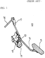
- Fig. 1 illustrates a schematic perspective view of a conventional pedal assembly for an accelerator having the above mentioned function.
- the conventional accelerator pedal assembly which is denoted by the reference numeral 10
- the conventional accelerator pedal assembly includes an accelerator rod 14 hingedly supported by a retainer 11 fixedly mounted to an automobile body.
- a spindle 12 is rotatably mounted to a desired portion of the retainer 11.
- a torsion coil spring 13 is fitted around the spindle 12.
- the accelerator rod 14 is coupled to the spindle 12 at an intermediate portion thereof so that it hinges about the spindle 12.
- the accelerator rod 14 is always urged in one direction by the torsion coil spring 13.
- a pedal 15 is fixedly mounted to one end of the accelerator rod 14.
- a cable 16 is connected at one end thereof to the other end of the accelerator rod 14. The other end of the cable 16 is coupled to a throttle body (not shown).
- the reference numeral 17 denotes a weight.
- the accelerator rod 14 hinges about the spindle 12 against the biasing force of the torsion coil spring 13 when the pedal 15 is depressed.
- the cable 16 connected to the end of the accelerator rod 14 opposite to the pedal 15 is drawn.
- the accelerator rod 14 hinges about the spindle 12 by virtue of the biasing force of the torsion coil spring 13 in an opposite direction, so that it returns to its original position.
- the drawn cable 16 returns to its original position, thereby causing the opening degree of the throttle valve to be decreased.
- the opening degree of the throttle valve can be adjusted only by the depression force of the driver applied to the pedal 15. Furthermore, the transmission of the depression force to the throttle valve is conducted only by the cable 16. For this reason, it is impossible to accurately manipulate the accelerator pedal assembly 10. In addition, a considerable force is required to manipulate the pedal 15 because of a resistance of the cable 16. In the case in which the cable 16 is old, it is further difficult to manipulate the pedal 15. In severe cases, the cable 16 may be damaged or broken.
- the manufacture process of the accelerator pedal assembly 10 has an increased number of assembling steps because it involves an assembling process for the cable 16.
- the present invention has been made in view of the above mentioned problems, and an object of the invention is to provide an electric accelerator pedal assembly of an automobile, which can be easily and accurately manipulated without any possibility of failures resulting from a damage of a cable used, while being capable of reducing the number of assembling steps.
- an electric accelerator pedal assembly of an automobile comprising: a retainer fixed to a body of the automobile; an accelerator rod mounted with a pedal at one end thereof, the accelerator rod being hingedly supported by the retainer; hinging angle transmitting means for transmitting a hinging angle of the accelerator rod in an amplified state; a potentiometer for detecting the amplified hinging angle transmitted from the hinging angle transmitting means, and outputting a detect signal indicative of the detected hinging angle; and an electronic control unit for receiving the detect signal from the potentiometer, and electrically controlling an opening degree of a throttle valve in response to the received detect signal.
- the accelerator rod is hingedly mounted to a spindle fixedly mounted to the retainer so that it hinges about the spindle.
- the hinging angle transmitting means comprises a first lever arm hingedly connected at one end thereof to the other end of the accelerator rod by a first connecting pin, a second lever arm hingedly connected at one end thereof to the other end of the first lever arm by a second connecting pin, and a rotating shaft fixed at one end thereof to the other end of the second lever arm while being coupled at the other end thereof to the potentiometer, whereby the hinging movement of the accelerator rod about the spindle is transmitted to the rotating shaft in an amplified state via the first and second lever arms, thereby causing the rotating shaft to generate an amplified rotation.
- a torsion coil spring is fitted around the spindle.
- the torsion coil spring serves to apply a biasing force to the accelerator rod toward an initial position of the accelerator rod, whereby the accelerator rod hinges from the initial position against the biasing force of the torsion coil spring when a depression force is applied to the pedal, while hinging toward the initial position by virtue of the biasing force of the torsion coil spring when the depression force applied to the pedal is reduced.
- a stopper is protruded from the retainer.
- the stopper serves to limit the hinging movement of the accelerator rod resulting from the biasing force of the torsion coil spring so that the hinging movement of the accelerator rod resulting from the biasing force of the torsion coil spring is stopped at the initial position of the accelerator rod.
- the electric accelerator pedal assembly which is denoted by the reference numeral 100, includes a retainer 110 fixed to an automobile body, an accelerator rod 120 hingedly supported by the retainer 110, a pair of lever arms, that is, a first lever arm 141 and a second lever arm 142, adapted to transmit a hinging angle of the accelerator rod 120 in an amplified state, and a potentiometer 150 for controlling the opening degree of a throttle valve (not shown) in accordance with the transmitted hinging angle.
- a spindle 112 is rotatably mounted to a lower portion of the retainer 110.
- a torsion coil spring 114 is fitted around the spindle 112.
- the torsion coil spring 114 is mounted at one end thereof to the retainer 110 while being mounted at the other end thereof to the accelerator rod 120.
- the torsion coil spring 114 serves to return the accelerator rod 120 to its initial position against a hinging movement of the accelerator rod 120 occurring in response to a pedal depression force applied to the accelerator rod 120.
- a stopper 116 is protruded from the retainer 110 in order to limit the return of the accelerator rod 120 made by virtue of the biasing force of the torsion coil spring 114. That is, the stopper 116 sets the initial position of the accelerator rod 120.
- a pedal 112 is fixedly mounted to one end of the accelerator rod 120 opposite to the lever arms 141 and 142.
- the lever arm 141 is hingedly coupled at one end thereof to the other end of the accelerator rod 120 by means of a first connecting pin 131. Accordingly, the accelerator rod 120 and first lever arm 141 conduct relative hinging movements with respect to each other about the first connecting pin 131.
- the accelerator rod 120 is arranged in such a fashion that it hinges from its initial position in one direction when the pedal is depressed against the biasing force of the torsion coil spring 114 while returning to its initial position in an opposite direction by virtue of the biasing force of the torsion coil spring 114 when the depression force applied to the pedal is released. As mentioned above, the returning movement of the accelerator rod 120 is limited to the initial position by the stopper 116.
- the second lever arm 142 is hingedly connected at one end thereof to the other end of the first lever arm 141 by means of a second connecting pin 132. Accordingly, the first and second lever arms 141 and 142 conduct relative hinging movements with respect to each other about the second connecting pin 132.
- the other end of the second lever arm 142 is fixedly coupled to a rotating shaft 152 protruded from the potentiometer 150. Accordingly, the hinging movement of the second lever arm 142 about the rotating shaft 152 is transmitted to the potentiometer 150 in the form of a rotation of the rotating shaft 152.
- the potentiometer 150 is fixedly mounted to an upper portion of the retainer 110.
- the rotating shaft 152 is partially received in the potentiometer 150.
- This potentiometer 150 is a variable resistor and serves to detect a variation in potential difference occurring due to a rotation of the rotating shaft 152, thereby recognizing a variation in the rotating angle of the rotating shaft 152.
- the accelerator rod 120 hinges about the spindle 112 in a counterclockwise direction when viewed in Fig. 2.
- the end of the accelerator rod 120 opposite to the pedal 122 moves in a forward direction when viewed in Fig. 2, so that the first connecting pin 131, the first lever arm 141 connected to the first connecting pin 131, and the second connecting pin 132 connected to the first lever arm 141 move forwardly.
- the second lever arm 142 hinges in a counterclockwise direction when viewed in Fig. 2. This hinging movement of the second lever arm 142 results in a counterclockwise rotation of the rotating shaft 152.
- the potentiometer 150 detects the rotating angle of the rotating shaft 152 in response to a variation in potential difference occurring due to the rotation of the rotating shaft 152, and informs an electronic control unit (not shown) of the detected rotating angle. In response to the rotating angle, the electronic control unit controls the throttle body, thereby controlling the opening degree of the throttle valve.
- the electric accelerator pedal assembly 100 operates in a fashion reverse to that in the case in which the pedal 122 is depressed. That is, the accelerator rod 120 hinges about the spindle 112 in a clockwise direction when viewed in Fig. 2. As a result, the end of the accelerator rod 120 opposite to the pedal 122 moves in a rearward direction when viewed in Fig. 2, so that the first connecting pin 131 connected to the accelerator rod 120, the first lever arm 141, and the second connecting pin 132 move rearwardly. Accordingly, the second lever arm 142 hinges in a clockwise direction when viewed in Fig. 2. This clockwise hinging movement of the second lever arm 142 results in a clockwise rotation of the rotating shaft 152.
- the potentiometer 150 informs the electronic control unit of the rotating angle of the rotating shaft 152, as in the above mentioned case. In response to the rotating angle, the electronic control unit controls the throttle body, thereby controlling the opening degree of the throttle valve.
- the opening degree of the throttle valve is increased whereas the opening degree of the throttle valve is decreased when the depression force is reduced.
- the rotating angle of the accelerator rod 120 rotating during a depression of the pedal 122 and a release of the depression force applied to the pedal 122 is amplified by the first and second lever arms 141 and 142. Accordingly, it is possible to more accurately control the opening degree of the throttle valve.
- the maximum range of the rotating angle of the rotating shaft 152 included in the potentiometer 150 is 82°.
- the electric accelerator pedal assembly 100 can achieve an accurate control for the opening degree of the throttle valve because the opening degree of the throttle valve is electrically controlled by the potentiometer 150, and the hinging angle of the accelerator rod 120 hinging during a depression of the pedal 122 or a release of the depression force is amplified by virtue of the first and second lever arms 141 and 142.
- the electric accelerator pedal assembly 100 also eliminates the problem associated with the accelerator cable, for example, a damage of the cable, and an increased number of assembling steps.
- the present invention provides an electric accelerator pedal assembly of an automobile, which can be easily and accurately manipulated without any possibility of failures resulting from a damage of a cable used, while being capable of reducing the number of assembling steps.
Landscapes
- Engineering & Computer Science (AREA)
- Chemical & Material Sciences (AREA)
- Combustion & Propulsion (AREA)
- Transportation (AREA)
- Mechanical Engineering (AREA)
- Physics & Mathematics (AREA)
- General Physics & Mathematics (AREA)
- Automation & Control Theory (AREA)
- Auxiliary Drives, Propulsion Controls, And Safety Devices (AREA)
- Control Of Throttle Valves Provided In The Intake System Or In The Exhaust System (AREA)
Applications Claiming Priority (2)
| Application Number | Priority Date | Filing Date | Title |
|---|---|---|---|
| KR9951507 | 1999-11-19 | ||
| KR1019990051507A KR100346437B1 (ko) | 1999-11-19 | 1999-11-19 | 자동차의 전기식 엑셀러레이터 페달 어셈블리 |
Publications (2)
| Publication Number | Publication Date |
|---|---|
| EP1101646A2 true EP1101646A2 (de) | 2001-05-23 |
| EP1101646A3 EP1101646A3 (de) | 2003-12-17 |
Family
ID=19620833
Family Applications (1)
| Application Number | Title | Priority Date | Filing Date |
|---|---|---|---|
| EP00125044A Withdrawn EP1101646A3 (de) | 1999-11-19 | 2000-11-16 | Elektrische Gaspedalanordnung für Kraftfahrzeuge |
Country Status (5)
| Country | Link |
|---|---|
| EP (1) | EP1101646A3 (de) |
| JP (1) | JP2001180327A (de) |
| KR (1) | KR100346437B1 (de) |
| CN (1) | CN1296888A (de) |
| ID (1) | ID28413A (de) |
Cited By (2)
| Publication number | Priority date | Publication date | Assignee | Title |
|---|---|---|---|---|
| CN102062001A (zh) * | 2010-12-22 | 2011-05-18 | 芜湖盛力制动有限责任公司 | 一种工程机械油门控制系统的油门操纵阀 |
| CN104742740A (zh) * | 2015-03-25 | 2015-07-01 | 山东科技大学 | 一种防止误踩汽车油门的装置及其应用 |
Families Citing this family (4)
| Publication number | Priority date | Publication date | Assignee | Title |
|---|---|---|---|---|
| SE518099C2 (sv) | 1997-11-21 | 2002-08-27 | Claes Johansson Automotive Ab | Inställbart pedalställ för ett fordon |
| GR1005429B (el) * | 2005-12-09 | 2007-02-01 | Ενισχυτης σηματος επιταχυνσης-αυτοματος πιλοτος για αυτοκινητα νεας τεχνολογιας | |
| CN105917841B (zh) * | 2016-06-13 | 2018-07-20 | 常州格力博有限公司 | 割草机 |
| CN108002307A (zh) * | 2017-12-28 | 2018-05-08 | 安徽合力股份有限公司宝鸡合力叉车厂 | 内燃静压叉车双踏板操纵系统 |
Family Cites Families (9)
| Publication number | Priority date | Publication date | Assignee | Title |
|---|---|---|---|---|
| JPS5797209U (de) * | 1980-12-04 | 1982-06-15 | ||
| JPH0448979Y2 (de) * | 1986-05-30 | 1992-11-18 | ||
| US4958607A (en) * | 1989-04-18 | 1990-09-25 | Williams Controls, Inc. | Foot pedal arrangement for electronic throttle control of truck engines |
| KR960007498U (ko) * | 1994-08-26 | 1996-03-13 | 전자식 엑셀레이터 | |
| KR970035982A (ko) * | 1995-12-30 | 1997-07-22 | 전성원 | 자동차의 전자제어 액셀레이터 |
| GB9604039D0 (en) * | 1996-02-26 | 1996-04-24 | Rearsby Automotive Ltd | Damped pedal mounting |
| FR2755071B1 (fr) * | 1996-10-24 | 1998-12-04 | Peugeot | Agencement d'une pedale d'accelerateur electronique pour vehicule automobile |
| US5887488A (en) * | 1997-04-16 | 1999-03-30 | Imo Industries, Inc. | Vehicular accelerator pedal apparatus |
| JP3466465B2 (ja) * | 1998-03-18 | 2003-11-10 | 株式会社日立ユニシアオートモティブ | 回動角検出装置 |
-
1999
- 1999-11-19 KR KR1019990051507A patent/KR100346437B1/ko not_active Expired - Fee Related
-
2000
- 2000-11-13 ID IDP20000977A patent/ID28413A/id unknown
- 2000-11-13 JP JP2000345444A patent/JP2001180327A/ja active Pending
- 2000-11-16 EP EP00125044A patent/EP1101646A3/de not_active Withdrawn
- 2000-11-17 CN CN00132448A patent/CN1296888A/zh active Pending
Non-Patent Citations (1)
| Title |
|---|
| None |
Cited By (3)
| Publication number | Priority date | Publication date | Assignee | Title |
|---|---|---|---|---|
| CN102062001A (zh) * | 2010-12-22 | 2011-05-18 | 芜湖盛力制动有限责任公司 | 一种工程机械油门控制系统的油门操纵阀 |
| CN102062001B (zh) * | 2010-12-22 | 2013-02-27 | 芜湖盛力制动有限责任公司 | 一种工程机械油门控制系统的油门操纵阀 |
| CN104742740A (zh) * | 2015-03-25 | 2015-07-01 | 山东科技大学 | 一种防止误踩汽车油门的装置及其应用 |
Also Published As
| Publication number | Publication date |
|---|---|
| ID28413A (id) | 2001-05-24 |
| KR20010047333A (ko) | 2001-06-15 |
| EP1101646A3 (de) | 2003-12-17 |
| JP2001180327A (ja) | 2001-07-03 |
| KR100346437B1 (ko) | 2002-08-01 |
| CN1296888A (zh) | 2001-05-30 |
Similar Documents
| Publication | Publication Date | Title |
|---|---|---|
| US8042430B2 (en) | Accelerator pedal for a vehicle | |
| US5385068A (en) | Electronic accelerator pedal assembly with pedal force sensor | |
| EP0393974B1 (de) | Pedalanordnung für die elektronische Kraftstoffregelung | |
| EP2390752B1 (de) | Gaspedal für ein fahrzeug | |
| EP1712440B1 (de) | Fahrzeugbremspedalanordnung | |
| US6520045B2 (en) | Vehicle pedal device assembly including two pedals whose non-operated positions are adjustable in vehicle longitudinal direction | |
| US7017441B2 (en) | Vehicle pedal device capable of adjusting pedal position in longitudinal direction of vehicle | |
| EP0990782B1 (de) | Gaspedal-mechanismus für fahrzeug | |
| US5812050A (en) | Electrical control apparatus with unidirectional tactile indicator | |
| US4319497A (en) | Device for turning over a clutch pedal | |
| EP1101646A2 (de) | Elektrische Gaspedalanordnung für Kraftfahrzeuge | |
| US20070266816A1 (en) | Adjustable pedal device | |
| JP3129609B2 (ja) | ペダルの踏込みストローク検出装置 | |
| JPH1083224A (ja) | 車両用アクセルペダル装置 | |
| US5188001A (en) | Accelerator pedal device | |
| GB2338774A (en) | Vehicle control pedal assemblies eg for drive-by-wire systems | |
| JP2000326754A (ja) | 自動車用アクセルペダル装置 | |
| US5697253A (en) | Motion transmission arrangement for controlling an internal combustion engine | |
| JP2000120453A (ja) | 操作エレメント装置 | |
| JP2004210100A (ja) | 車両のペダル前後位置調節装置 | |
| JP3079875B2 (ja) | 電気制御式アクセルペダル装置 | |
| US5168850A (en) | Load adjustment device | |
| US4537168A (en) | Engine component position indicating system | |
| JPH051724A (ja) | クラツチペダルの踏力軽減装置 | |
| US4005616A (en) | Foot pedal assembly with a return spring |
Legal Events
| Date | Code | Title | Description |
|---|---|---|---|
| PUAI | Public reference made under article 153(3) epc to a published international application that has entered the european phase |
Free format text: ORIGINAL CODE: 0009012 |
|
| AK | Designated contracting states |
Kind code of ref document: A2 Designated state(s): AT BE CH CY DE DK ES FI FR GB GR IE IT LI LU MC NL PT SE TR |
|
| AX | Request for extension of the european patent |
Free format text: AL;LT;LV;MK;RO;SI |
|
| PUAL | Search report despatched |
Free format text: ORIGINAL CODE: 0009013 |
|
| AK | Designated contracting states |
Kind code of ref document: A3 Designated state(s): AT BE CH CY DE DK ES FI FR GB GR IE IT LI LU MC NL PT SE TR |
|
| AX | Request for extension of the european patent |
Extension state: AL LT LV MK RO SI |
|
| 17P | Request for examination filed |
Effective date: 20040218 |
|
| AKX | Designation fees paid |
Designated state(s): DE FR GB |
|
| 17Q | First examination report despatched |
Effective date: 20041001 |
|
| STAA | Information on the status of an ep patent application or granted ep patent |
Free format text: STATUS: THE APPLICATION IS DEEMED TO BE WITHDRAWN |
|
| 18D | Application deemed to be withdrawn |
Effective date: 20050212 |