EP1101657A2 - Method and means of triggering a safety device, especially in a motor vehicle - Google Patents
Method and means of triggering a safety device, especially in a motor vehicle Download PDFInfo
- Publication number
- EP1101657A2 EP1101657A2 EP00122289A EP00122289A EP1101657A2 EP 1101657 A2 EP1101657 A2 EP 1101657A2 EP 00122289 A EP00122289 A EP 00122289A EP 00122289 A EP00122289 A EP 00122289A EP 1101657 A2 EP1101657 A2 EP 1101657A2
- Authority
- EP
- European Patent Office
- Prior art keywords
- crash
- sensor
- sensor signal
- control
- signal
- Prior art date
- Legal status (The legal status is an assumption and is not a legal conclusion. Google has not performed a legal analysis and makes no representation as to the accuracy of the status listed.)
- Ceased
Links
- 238000000034 method Methods 0.000 title claims abstract description 30
- 238000011156 evaluation Methods 0.000 claims abstract description 23
- 230000009466 transformation Effects 0.000 claims abstract description 12
- 230000000977 initiatory effect Effects 0.000 claims abstract description 3
- 230000001133 acceleration Effects 0.000 claims description 18
- 238000001228 spectrum Methods 0.000 description 6
- 230000008569 process Effects 0.000 description 5
- 230000008901 benefit Effects 0.000 description 4
- 230000002123 temporal effect Effects 0.000 description 3
- 230000001960 triggered effect Effects 0.000 description 3
- 238000011161 development Methods 0.000 description 2
- 230000018109 developmental process Effects 0.000 description 2
- 238000010586 diagram Methods 0.000 description 2
- 230000004069 differentiation Effects 0.000 description 2
- 230000003595 spectral effect Effects 0.000 description 2
- 208000027418 Wounds and injury Diseases 0.000 description 1
- 230000004913 activation Effects 0.000 description 1
- 230000006978 adaptation Effects 0.000 description 1
- 230000003044 adaptive effect Effects 0.000 description 1
- 238000013459 approach Methods 0.000 description 1
- 230000006378 damage Effects 0.000 description 1
- 230000001419 dependent effect Effects 0.000 description 1
- 238000002474 experimental method Methods 0.000 description 1
- 208000014674 injury Diseases 0.000 description 1
- 230000010354 integration Effects 0.000 description 1
- 238000012545 processing Methods 0.000 description 1
- 239000004575 stone Substances 0.000 description 1
- 238000012360 testing method Methods 0.000 description 1
- 238000000844 transformation Methods 0.000 description 1
Images


Classifications
-
- B—PERFORMING OPERATIONS; TRANSPORTING
- B60—VEHICLES IN GENERAL
- B60R—VEHICLES, VEHICLE FITTINGS, OR VEHICLE PARTS, NOT OTHERWISE PROVIDED FOR
- B60R21/00—Arrangements or fittings on vehicles for protecting or preventing injuries to occupants or pedestrians in case of accidents or other traffic risks
- B60R21/01—Electrical circuits for triggering passive safety arrangements, e.g. airbags, safety belt tighteners, in case of vehicle accidents or impending vehicle accidents
- B60R21/013—Electrical circuits for triggering passive safety arrangements, e.g. airbags, safety belt tighteners, in case of vehicle accidents or impending vehicle accidents including means for detecting collisions, impending collisions or roll-over
- B60R21/0132—Electrical circuits for triggering passive safety arrangements, e.g. airbags, safety belt tighteners, in case of vehicle accidents or impending vehicle accidents including means for detecting collisions, impending collisions or roll-over responsive to vehicle motion parameters, e.g. to vehicle longitudinal or transversal deceleration or speed value
- B60R21/01332—Electrical circuits for triggering passive safety arrangements, e.g. airbags, safety belt tighteners, in case of vehicle accidents or impending vehicle accidents including means for detecting collisions, impending collisions or roll-over responsive to vehicle motion parameters, e.g. to vehicle longitudinal or transversal deceleration or speed value by frequency or waveform analysis
-
- B—PERFORMING OPERATIONS; TRANSPORTING
- B60—VEHICLES IN GENERAL
- B60R—VEHICLES, VEHICLE FITTINGS, OR VEHICLE PARTS, NOT OTHERWISE PROVIDED FOR
- B60R21/00—Arrangements or fittings on vehicles for protecting or preventing injuries to occupants or pedestrians in case of accidents or other traffic risks
- B60R21/01—Electrical circuits for triggering passive safety arrangements, e.g. airbags, safety belt tighteners, in case of vehicle accidents or impending vehicle accidents
- B60R21/013—Electrical circuits for triggering passive safety arrangements, e.g. airbags, safety belt tighteners, in case of vehicle accidents or impending vehicle accidents including means for detecting collisions, impending collisions or roll-over
- B60R21/0136—Electrical circuits for triggering passive safety arrangements, e.g. airbags, safety belt tighteners, in case of vehicle accidents or impending vehicle accidents including means for detecting collisions, impending collisions or roll-over responsive to actual contact with an obstacle, e.g. to vehicle deformation, bumper displacement or bumper velocity relative to the vehicle
-
- B—PERFORMING OPERATIONS; TRANSPORTING
- B60—VEHICLES IN GENERAL
- B60R—VEHICLES, VEHICLE FITTINGS, OR VEHICLE PARTS, NOT OTHERWISE PROVIDED FOR
- B60R21/00—Arrangements or fittings on vehicles for protecting or preventing injuries to occupants or pedestrians in case of accidents or other traffic risks
- B60R2021/0002—Type of accident
- B60R2021/0004—Frontal collision
-
- B—PERFORMING OPERATIONS; TRANSPORTING
- B60—VEHICLES IN GENERAL
- B60R—VEHICLES, VEHICLE FITTINGS, OR VEHICLE PARTS, NOT OTHERWISE PROVIDED FOR
- B60R21/00—Arrangements or fittings on vehicles for protecting or preventing injuries to occupants or pedestrians in case of accidents or other traffic risks
- B60R2021/0002—Type of accident
- B60R2021/0006—Lateral collision
-
- B—PERFORMING OPERATIONS; TRANSPORTING
- B60—VEHICLES IN GENERAL
- B60R—VEHICLES, VEHICLE FITTINGS, OR VEHICLE PARTS, NOT OTHERWISE PROVIDED FOR
- B60R21/00—Arrangements or fittings on vehicles for protecting or preventing injuries to occupants or pedestrians in case of accidents or other traffic risks
- B60R21/01—Electrical circuits for triggering passive safety arrangements, e.g. airbags, safety belt tighteners, in case of vehicle accidents or impending vehicle accidents
- B60R2021/01006—Mounting of electrical components in vehicles
-
- B—PERFORMING OPERATIONS; TRANSPORTING
- B60—VEHICLES IN GENERAL
- B60R—VEHICLES, VEHICLE FITTINGS, OR VEHICLE PARTS, NOT OTHERWISE PROVIDED FOR
- B60R21/00—Arrangements or fittings on vehicles for protecting or preventing injuries to occupants or pedestrians in case of accidents or other traffic risks
- B60R21/01—Electrical circuits for triggering passive safety arrangements, e.g. airbags, safety belt tighteners, in case of vehicle accidents or impending vehicle accidents
- B60R21/013—Electrical circuits for triggering passive safety arrangements, e.g. airbags, safety belt tighteners, in case of vehicle accidents or impending vehicle accidents including means for detecting collisions, impending collisions or roll-over
- B60R21/0134—Electrical circuits for triggering passive safety arrangements, e.g. airbags, safety belt tighteners, in case of vehicle accidents or impending vehicle accidents including means for detecting collisions, impending collisions or roll-over responsive to imminent contact with an obstacle, e.g. using radar systems
Definitions
- the invention relates to a method for triggering a safety device, in particular of a motor vehicle, in which one generated by a crash sensor Sensor signal passed to a control / evaluation device and there to the Crash information contained evaluated using a frequency analysis and in which a control signal initiating the safety device is generated, if the control / evaluation device detects the presence of a crash, and such a device.
- the known method therefore uses a windowed Fourier transformation to create a time-resolved frequency analysis of the Acceleration signal by for each time step in the Fourier analysis of the Acceleration signal the frequency values 1 to n of the previous time spectra be taken into account.
- This windowed Fourier transformation shifts the calculation with each time step, d. that is, along with the current Acceleration value transformed the previous 31 acceleration values become.
- This windowed Fourier transformation is carried out continuously and at every new cycle, d. that is, recalculated with each new time step, so that for every time step produces a signal image in which the transformed acceleration value in Dependence of the frequency, the time and the amplitude is shown.
- the so determined spectral acceleration density can now be used for evaluation, the course of the amplitude of the spectral acceleration density at different Frequency values shows a different height and at a certain one Frequency value reveals a maximum value.
- Frequency values can occur based on the known probabilities at which frequencies obtained from the acceleration signal a simple or a complicated crash occurs, according to the information in the aforementioned document the differentiation of the amplitude values with selectable frequency spectra a reliable and reliable deployment of restraint systems can be set.
- crash signals from the so-called misuse signals i.e. signals that are not caused by a crash are and if they occur naturally not the safety devices of the Motor vehicle to be activated, or of signals in which a collision of the motor vehicle with an obstacle, but due to the small There is no risk of injury to the vehicle occupants, and accordingly a safety device should not be triggered.
- the known method now has the disadvantage that it is Fourier analysis basically only allowed the occurring sensor signals with regard to the therein contained frequency spectra and the amplitudes of the associated waves analyze; however, it basically leaves no statements about the temporal occurrence individual frequencies or frequency ranges. Now to try this too achieve, in the known method into the Fourier transform definable number of previous periods in this analysis process included, so that a specific time window is taken into account.
- the measures according to the invention have the advantage that the sensor signal of the Crash sensors are shown broken down into their frequency components at all times can be.
- the wavelet transform of the sensor signal is therefore of an advantageous type and way a function of time and frequency so that the sensor signal using of the method according to the invention in an advantageous manner particularly simple in its frequency components can be disassembled, with the individual frequency components can be determined.
- Another, particularly important one The advantage of the method according to the invention is that the wavelet transformation causes the frequency analysis of the Sensor signal is independent of the choice of a time window.
- An advantageous development of the invention provides that the wavelet transform the sensor signal with characteristic accident spectra in the evaluation device are stored, compared and at a within predetermined limits lying correspondence of the wavelet transform with the stored Signal pattern the triggering of the corresponding safety device carried out becomes.
- Such a measure has the advantage that it is particularly simple empirically obtained signal patterns in the triggering process of the safety devices are included.
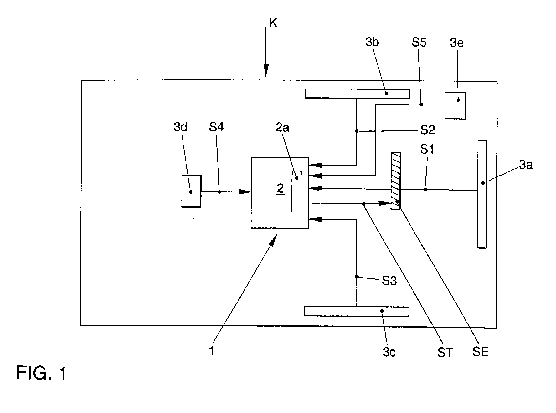
- FIG. 1 is now generally designated 1 device for performing a Method for triggering at least one safety device SE Motor vehicle K shown.
- the device 1 has a control / evaluation device 2 to which the sensor signals a number of crash sensors 3a-3e are supplied.
- the crash sensor 3a is designed as a deformation sensor, through which a deformation of the front area of the motor vehicle K can be detected and a sensor signal S1 representing this information to control / evaluation device 2 is conductive.
- the two crash sensors 3b, 3c are side impact sensors formed that a deformation of the side region of the motor vehicle K, which at a Side impact occurs, and capture appropriate sensor signals S2, S3 to the control / evaluation device 2 direct.
- the crash sensor 3d is an acceleration sensor trained who measures the acceleration occurring in an accident and a corresponding signal S4 representing this information is generated.
- the sensor 3e is designed as a pre-crash sensor, through which the environment of the motor vehicle K can be monitored and if a defined approach is exceeded Object to the motor vehicle K, a sensor signal S5 can be generated, which is then sent to the control / evaluation device 2 is directed.
- the control / evaluation device 2 which is supplied with the sensor signal S1 of the crash sensor 3a, now prepares it in in a manner known per se and therefore no longer described in more detail for the subsequent signal processing process, it being for certain Purpose is quite possible that the sensor signal S1 immediately one Frequency analysis unit 2a of the control / evaluation device 2 is supplied.
- the Frequency analysis unit 2a now performs a wavelet transformation of the one supplied to it Sensor signal S1 through.
- the wavelet transform of the sensor signal S1 is a weighted superposition of time resolved frequency spectra, making it the wavelet transform of the sensor signal S1 advantageously allows not only the frequency components of the sensor signal S1 and their amplitudes, but also the temporal course of these frequency components determine.
- FIG. 2 shows the wavelet transform of a typical sensor signal.
- the time in milliseconds is on the abscissa of this diagram and the time on the ordinate Frequency shown in kilohertz.
- the Sensor signal has four maxima, which are approximately at 2, 5.5, 8 and 9.5 ms.
- the Amplitudes of the individual frequency components of the maxima are due to the iso lines ?? given.
- Figure 2 thus clearly shows that it is the method described in advantageously allowed, simple and by choosing a time window independently break down a sensor signal into its frequency spectra, whereby for each individual frequency component their amplitude and their temporal occurrence can be determined.
- the wavelet transform is now included in the control / evaluation device 2 compared stored crash patterns representing typical crash scenarios, it is preferred that these crash patterns are determined in experiments by that the sensor signals S1-S5 were simulated in a crash test or in a laboratory Crash of the motor vehicle K is determined and also by that described above Processes have been prepared so that the control / evaluation device 2 Wavelet transform of the currently occurring sensor signals S1-S5 with wavelet transforms of sensor signals under a defined conditions occurring crash were recorded is compared. Such The procedure advantageously allows a particularly simple one Classification of the accident and therefore a corresponding situation-adapted Activation of the safety devices.
- control / evaluation unit 2 If there is an agreement between the Sensor signal S1 or its wavelet transform and one of the stored Detected crash pattern, the control / evaluation unit 2 generates a control signal ST, which triggers the safety device SE.
Landscapes
- Engineering & Computer Science (AREA)
- Mechanical Engineering (AREA)
- Air Bags (AREA)
- Electric Propulsion And Braking For Vehicles (AREA)
Abstract
Die Erfindung betrifft ein Verfahren zur Auslösung einer Sicherheitseinrichtung, insbesondere eines Kraftfahrzeugs, bei dem ein von einem Crash-Sensor (2a-2e) erzeugtes Sensorsignal (S1-S5) zu einer Steuer-/Auswerteeinrichtung (2) geleitet und dort auf die darin enthaltene Crashinformation unter Zuhilfenahme einer Frequenzanalyse ausgewertet wird, und bei dem ein die Sicherheitseinrichtung (SE) initiierendes Steuersignal (ST) erzeugt wird, wenn durch die Steuer-/Auswerteeinrichtung (2) das Vorliegen eines Crashs erkannt wird.The invention relates to a method for triggering a safety device, in particular of a motor vehicle in which a crash sensor (2a-2e) generated sensor signal (S1-S5) to a control / evaluation device (2) and there on the crash information contained therein with the aid of a frequency analysis is evaluated, and in which one initiating the safety device (SE) Control signal (ST) is generated when the control / evaluation device (2) Presence of a crash is detected.
Erfindungsgemäß ist vorgesehen, daß die Frequenzanalyse des Sensorsignals (S1-S5)
mittels einer Wavelet-Transformation durchgeführt wird.
Description
Die Erfindung betrifft ein Verfahren zur Auslösung einer Sicherheitseinrichtung, insbesondere eines Kraftfahrzeugs, bei dem ein von einem Crash-Sensor erzeugtes Sensorsignal zu einer Steuer-/Auswerteeinrichtung geleitet und dort auf die darin enthaltene Crashinformation unter Zuhilfenahme einer Frequenzanalyse ausgewertet wird, und bei dem ein die Sicherheitseinrichtung initiierendes Steuersignal erzeugt wird, wenn durch die Steuer-/Auswerteeinrichtung das Vorliegen eines Crashs erkannt wird, sowie eine derartige Vorrichtung.The invention relates to a method for triggering a safety device, in particular of a motor vehicle, in which one generated by a crash sensor Sensor signal passed to a control / evaluation device and there to the Crash information contained evaluated using a frequency analysis and in which a control signal initiating the safety device is generated, if the control / evaluation device detects the presence of a crash, and such a device.
Ein derartiges Verfahren ist aus der DE 44 45 996 bekannt. In dieser Druckschrift ist ein Verfahren zur Auslösung von Rückhaltemitteln, insbesondere in Kraftfahrzeugen, beschrieben, bei denen ein Beschleunigungssignal eines Crash-Sensors gemessen wird. Dieses Beschleunigungssignal wird durch eine zeitliche Integration in ein Geschwindigkeitssignal umgewandelt und das Geschwindigkeitssignal wird zur Bestimmung eines Auslösekriteriums mit einer Auslöseschwelle verglichen. Hierbei ist vorgesehen, daß die Integration des Beschleunigungssignals in Abhängigkeit einer Frequenzanalyse des Beschleunigungssignals beeinflußt wird, wobei die Frequenzanalyse mittels einer Fast-Fourier-Transformation und der dazu benötigten Teiloperationen durchgeführt wird, indem zu einem vorgebbaren Zeitschritt des Beschleunigungssignals die Fast-Fourier-Transformation mit einer festlegbaren Anzahl vorangegangener Zeitschritte mit den dort vorhandenen Beschleunigungssignalen durchgeführt wird. Das bekannte Verfahren verwendet also eine gefensterte Fourier-Transformation zur Erstellung einer zeitlich aufgelösten Frequenzanalyse des Beschleunigungssignals, indem für jeden Zeitschritt bei der Fourier-Analyse des Beschleunigungssignals die Frequenzwerte 1 bis n der vorangegangenen Zeitspektren berücksichtigt werden. Durch diese gefensterte Fourier-Transformation verschiebt sich die Berechnung mit jedem Zeitschritt, d. h., daß zusammen mit dem aktuellen Beschleunigungswert die vorangegangenen 31 Beschleunigungswerte transformiert werden. Diese gefensterte Fourier-Transformation wird fortlaufend durchgeführt und bei jedem neuen Zyklus, d. h., bei jedem neuen Zeitschritt, neu berechnet, so daß sich für jeden Zeitschritt ein Signalbild ergibt, bei dem der transformierte Beschleunigungswert in Abhängigkeit der Frequenz, der Zeit und der Ampitude dargestellt ist. Die derart ermittelte spektrale Beschleunigungsdichte kann nunmehr zur Auswertung herangezogen werden, wobei der Ampitudenverlauf der spektralen Beschleunigungsdichte bei unterschiedlichen Frequenzwerten eine unterschiedliche Höhe zeigt und bei einem bestimmten Frequenzwert einen Maximalwert erkennen läßt. Indem nun die Ampituden differenziert werden, wobei eine Differenzierung zur bestimmten, für Crashs typischen Frequenzwerten erfolgt, kann aufgrund der bekannten Wahrscheinlichkeiten, bei welchen sich aus dem Beschleunigungssignal gewonnenen Frequenzen ein einfacher oder ein komplizierter Crash eintritt, soll nach den Angaben der vorgenannten Druckschrift durch die Differenzierung der Ampitudenwerte bei wählbaren Frequenzspektren eine sichere und zuverlässige Auslösung von Rückhaltesysteme eingestellt werden.Such a method is known from DE 44 45 996. In this publication there is a Method for triggering restraint devices, especially in motor vehicles, described, in which an acceleration signal of a crash sensor is measured. This acceleration signal is integrated into a time Speed signal converted and the speed signal becomes Determination of a trigger criterion compared to a trigger threshold. Here is provided that the integration of the acceleration signal depending on a Frequency analysis of the acceleration signal is influenced, the Frequency analysis using a Fast Fourier transform and the required ones Partial operations is carried out by at a predetermined time step of the Acceleration signal the Fast Fourier transform with a definable number previous time steps with the acceleration signals available there is carried out. The known method therefore uses a windowed Fourier transformation to create a time-resolved frequency analysis of the Acceleration signal by for each time step in the Fourier analysis of the Acceleration signal the frequency values 1 to n of the previous time spectra be taken into account. This windowed Fourier transformation shifts the calculation with each time step, d. that is, along with the current Acceleration value transformed the previous 31 acceleration values become. This windowed Fourier transformation is carried out continuously and at every new cycle, d. that is, recalculated with each new time step, so that for every time step produces a signal image in which the transformed acceleration value in Dependence of the frequency, the time and the amplitude is shown. The so determined spectral acceleration density can now be used for evaluation, the course of the amplitude of the spectral acceleration density at different Frequency values shows a different height and at a certain one Frequency value reveals a maximum value. By differentiating the amplitudes differentiation from the specific one typical of crashes Frequency values can occur based on the known probabilities at which frequencies obtained from the acceleration signal a simple or a complicated crash occurs, according to the information in the aforementioned document the differentiation of the amplitude values with selectable frequency spectra a reliable and reliable deployment of restraint systems can be set.
Die vorgenannte Analyse der Sensorsignale wird deshalb durchgeführt, um Signale, die durch einen Crash verursacht werden, und bei denen die Sicherheitseinrichtungen des Kraftfahrzeugs ausgelöst werden sollen, also den sogenannten Crash-Signalen, von den sogenannten Misuse-Signalen, also von Signalen, die nicht durch einen Crash verursacht werden und bei deren Auftreten naturgemäß nicht die Sicherheitseinrichtungen des Kraftfahrzeugs aktiviert werden sollen, oder von Signalen, bei denen zwar eine Kollision des Kraftfahrzeugs mit einem Hindernis stattfindet, aber aufgrund der geringen Unfallschwere keine Verletzungsgefahr für die Fahrzeuginsassen besteht und demgemäß keine Auslösung einer Sicherheitseinrichtung erfolgen soll, zu unterscheiden. Es sollen z. B. bestimmte Rückhalteeinrichtungen für die Fahrzeuginsassen, z. B. Seitenairbags, z. B. nicht auslösen, wenn ein Radfahrer in die Tür des Fahrzeugs fährt, oder wenn ein Stein von unten gegen die Fahrzeugtür geschleudert wird.The aforementioned analysis of the sensor signals is therefore carried out to determine signals caused by a crash, and where the safety devices of the Motor vehicle should be triggered, so-called crash signals from the so-called misuse signals, i.e. signals that are not caused by a crash are and if they occur naturally not the safety devices of the Motor vehicle to be activated, or of signals in which a collision of the motor vehicle with an obstacle, but due to the small There is no risk of injury to the vehicle occupants, and accordingly a safety device should not be triggered. It should B. certain restraint devices for vehicle occupants, e.g. B. side airbags, e.g. B. not trigger when a cyclist drives into the door of the vehicle or when a stone is hurled against the vehicle door from below.
Das bekannte Verfahren besitzt nun den Nachteil, daß es die Fourier-Analyse grundsätzlich nur erlaubt, die auftretenden Sensorsignale hinsichtlich der darin enthaltenen Frequenzspektren und der Ampituden der dazugehörigen Wellen zu analysieren; sie läßt jedoch grundsätzlich keine Aussagen über das zeitliche Auftreten einzelner Frequenzen oder Frequenzbereiche zu. Um nun zu versuchen, dies zu erreichen, wird bei dem bekannten Verfahren in die Fourier-Transformation eine festlegbare Anzahl vorangegangener Zeitabschnitte in diesen Analyseprozeß miteinbezogen, so daß jeweils ein bestimmtes Zeitfenster berücksichtigt wird. Eine derartige Frequenzanalyse, bei der die Fenstergröße willkürlich durch die Anzahl der vorangegangenen Teilabschnitte, die in den Analyseprozeß miteingehen, festgelegt wird, ist jedoch äußerst kritisch bezüglich der Wahl dieses Zeitfensters: Wird das Zeitfenster zu groß gewählt, so tritt eine Verschmierung des Informationsgehalts auf, wird es zu klein gewählt, ergibt die Analyse nur bestimmte Frequenzkomponenten, die dann kein Rückschluß mehr auf das Gesamtsignal erlauben, so daß es bei dem bekannten Verfahren durchaus der Fall sein kann, daß aufgrund einer nicht-angepaßten Wahl der Fenstergröße ein einen Crash repräsentierendes Sensorsignal als irrelevant für die Auslösung der Sicherheitseinrichtung aufgefaßt oder ein Misuse-Signal dazu führt, daß die Sicherheitseinrichtungen ausgelöst werden. Diese starre Fensterung läßt also eine signaladaptive, d. h., eine signalangepaßte Auflösung des Sensorsignals nicht zu.The known method now has the disadvantage that it is Fourier analysis basically only allowed the occurring sensor signals with regard to the therein contained frequency spectra and the amplitudes of the associated waves analyze; however, it basically leaves no statements about the temporal occurrence individual frequencies or frequency ranges. Now to try this too achieve, in the known method into the Fourier transform definable number of previous periods in this analysis process included, so that a specific time window is taken into account. A such frequency analysis, in which the window size is arbitrarily determined by the number of previous sections that are included in the analysis process, However, is extremely critical with regard to the choice of this time window: If the time window becomes chosen large, the information content becomes smeared, it becomes too small selected, the analysis only yields certain frequency components, which then do not Allow more conclusions about the overall signal, so that it is in the known Procedure may well be the case that due to an unmatched choice of Window size a sensor signal representing a crash as irrelevant to the Triggering of the safety device or a misuse signal leads to the fact that the safety devices are triggered. This rigid fenestration leaves one signal adaptive, d. that is, a signal-adapted resolution of the sensor signal is not.
Es ist daher Aufgabe der vorliegenden Erfindung, ein Verfahren und eine Vorrichtung der eingangs genannten Art derart weiterzubilden, daß eine bessere Adaption der Frequenzanalyse an den Signalverlauf gegeben ist.It is therefore an object of the present invention, a method and an apparatus of the type mentioned in such a way that a better adaptation of the Frequency analysis of the signal curve is given.
Diese Aufgabe wird durch das erfindungsgemäße Verfahren dadurch gelöst, daß die Frequenzanalyse des Sensorsignals mittels einer Wavelet-Transformation durchgeführt wird.This object is achieved by the inventive method in that the Frequency analysis of the sensor signal carried out using a wavelet transformation becomes.
Die erfindungsgemäßen Maßnahmen besitzen den Vorteil, daß das Sensorsignal des Crash-Sensors zu jedem Zeitpunkt in seine Frequenzbestandteile zerlegt dargestellt werden kann. Die Wavelet-Transformierte des Sensorsignals ist also in vorteilhafter Art und Weise eine Funktion der Zeit und der Frequenz, so daß das Sensorsignal mit Hilfe des erfindungsgemäßen Verfahrens in vorteilhafter Art und Weise besonders einfach in seine Frequenzbestandteile zerlegt darstellen läßt, wobei zu jedem Zeitpunkt die einzelnen Frequenzkomponenten ermittelbar sind. Ein weiterer, besonders wichtiger Vorteil des erfindungsgemäßen Verfahrens besteht darin, daß die Wavelet-Transformation in vorteilhafter Art und Weise bewirkt, daß die Frequenzanalyse des Sensorsignals unabhängig von der Wahl eines Zeitfensters ist.The measures according to the invention have the advantage that the sensor signal of the Crash sensors are shown broken down into their frequency components at all times can be. The wavelet transform of the sensor signal is therefore of an advantageous type and way a function of time and frequency so that the sensor signal using of the method according to the invention in an advantageous manner particularly simple in its frequency components can be disassembled, with the individual frequency components can be determined. Another, particularly important one The advantage of the method according to the invention is that the wavelet transformation causes the frequency analysis of the Sensor signal is independent of the choice of a time window.
Eine vorteilhafte Weiterbildung der Erfindung sieht vor, daß die Wavelet-Transformierte des Sensorsignals mit charakteristischen Unfallspektren, die in der Auswerteeinrichtung gespeichert sind, verglichen wird und bei einer innerhalb vorgegebener Grenzen liegenden Übereinstimmung der Wavelet-Transformierten mit dem gespeicherten Signalmuster die Auslösung der entsprechenden Sicherheitseinrichtung durchgeführt wird. Eine derartige Maßnahme besitzt den Vorteil, daß hierdurch besonders einfach empirisch gewonnene Signalmuster in den Auslöseprozeß der Sicherheitseinrichtungen miteinbeziehbar sind.An advantageous development of the invention provides that the wavelet transform the sensor signal with characteristic accident spectra in the evaluation device are stored, compared and at a within predetermined limits lying correspondence of the wavelet transform with the stored Signal pattern the triggering of the corresponding safety device carried out becomes. Such a measure has the advantage that it is particularly simple empirically obtained signal patterns in the triggering process of the safety devices are included.
Weitere vorteilhafte Weiterbildungen sind Gegenstand der Unteransprüche.Further advantageous developments are the subject of the dependent claims.
Weitere Einzelheiten und Vorteile der Erfindung sind dem Ausführungsbeispiel zu entnehmen, das im folgenden anhand der Figuren beschrieben wird. Es zeigen:
- Figur 1
- eine schematische Darstellung einer Vorrichtung zur Durchführung des Verfahrens, und
Figur 2- eine Darstellung einer Wavelet-Transformierten eines Sensorsignals.
- Figure 1
- a schematic representation of an apparatus for performing the method, and
- Figure 2
- a representation of a wavelet transform of a sensor signal.
In Figur 1 ist nun eine allgemein mit 1 bezeichnete Vorrichtung zur Durchführung eines
Verfahrens zur Auslösung mindestens einer Sicherheitseinrichtung SE eines
Kraftfahrzeugs K dargestellt. Die Vorrichtung 1 weist eine Steuer-/Auswerteeinrichtung 2
auf, der die Sensorsignale eine Anzahl von Crash-Sensoren 3a-3e zugeführt sind. Im
beschriebenen Fall ist der Crash-Sensor 3a als ein Deformationssensor ausgebildet,
durch den eine Deformation des Frontbereichs des Kraftfahrzeugs K erfaßbar und ein
diese Information repräsentierendes Sensorsignal S1 zur Steuer-/Auswerteeinrichtung 2
leitbar ist. Die beiden Crash-Sensoren 3b, 3c sind als Seitenaufprall-Sensoren
ausgebildet, die eine Deformation des Seitenbereichs des Kraftfahrzeugs K, die bei einem
Seitenaufprall auftritt, erfassen und entsprechende Sensorsignale S2, S3 zur Steuer/Auswerteeinrichtung
2 leiten. Der Crash-Sensor 3d ist als Beschleunigungssensor
ausgebildet, der die bei einem Unfall auftretende Beschleunigung mißt und ein
entsprechendes, diese Information repräsentierendes Signal S4 erzeugt. Der Sensor 3e
ist als ein Pre-Crash-Sensor ausgebildet, durch den die Umgebung des Kraftfahrzeugs K
überwachbar und bei einer definierte Kriterien überschreitenden Annäherung eines
Objekts an das Kraftfahrzeug K ein Sensorsignal S5 erzeugbar ist, das dann zur Steuer/Auswerteeinrichtung
2 geleitet wird.In Figure 1 is now generally designated 1 device for performing a
Method for triggering at least one safety device SE
Motor vehicle K shown. The device 1 has a control /
Es ist dem Fachmann klar ersichtlich, daß die vorgenannte, beispielhafte Auflistung der
als Crash-Sensor 3a-3e einsetzbaren Sensoren nur exemplarischen Charakter besitzen
und keinesfalls als abschließend zu betrachten ist. Vielmehr ist es möglich, das
beschriebene Verfahren für jeden Sensor einzusetzen, durch den sicherheitsrelevante
Informationen erfaßbar und ein diese Informationen repräsentierendes Sensorsignal
erzeugbar ist.It is clear to the person skilled in the art that the aforementioned exemplary listing of the
sensors which can be used as
Das Verfahren wird im folgenden anhand des Crash-Sensors 3a beschrieben, da die
Vorgangsweise bei den von den weiteren Crash-Sensoren 3b-3e gelieferten
Sensorsignalen S2-S5 in entsprechender Weise erfolgt: Die Steuer-/Auswerteeinrichtung
2, der das Sensorsignal S1 des Crash-Sensors 3a zugeführt wird, bereitet dieses nun in
an und für sich bekannter und daher nicht mehr näher beschriebenen Art und Weise für
den nachfolgenden Signalverarbeitungsvorgang auf, wobei es für bestimmte
Einsatzzwecke durchaus möglich ist, daß das Sensorsignal S1 unmittelbar einer
Frequenzanalyseeinheit 2a der Steuer-/Auswerteeinrichtung 2 zugeführt wird. Die
Frequenzanalyseeinheit 2a führt nun eine Wavelet-Transformation des ihr zugeführten
Sensorsignals S1 durch. Derartige Frequenzanalyseeinheiten 2a zur Durchführung einer
Wavelet-Transformation sind bekannt, so daß die genaue Funktionsweise einer
derartigen Frequenzanalyseeinheit 2a hier nicht mehr beschrieben werden muß. Es wird
in diesem Zusammenhang auf den Artikel "An Introduction to Wavelets" von Amara
Graps, erschienen in IEEE Computational Science and Engineering, Sommer 1995, vol.
2, num. 2, verwiesen, dessen Inhalt hiermit offenbart ist. Die Wavelet-Transformierte des
Sensorsignals S1 ist nun eine Funktion der Zeit t und der Frequenz f, d. h., die Wavelet-Transformierte
des Sensorsignals S1 ist eine gewichtete Superposition von zeitlich
aufgelösten Frequenzspektren, so daß es die Wavelet-Transformierte des Sensorsignals
S1 in vorteilhafter Art und Weise erlaubt, nicht nur die Frequenzanteile des Sensorsignals
S1 und deren Ampituden, sondern auch den zeitlichen Verlauf dieser Frequenzanteile zu
ermitteln.The method is described below using the
In Figur 2 ist nun die Wavelet-Transformierte eines typischen Sensorsignals dargestellt. Auf der Abszisse dieses Diagramms ist die Zeit in Millisekunden und auf der Ordinate die Frequenz in Kilohertz dargestellt. Man erkennt auf diesem Isoplot-Diagramm, daß das Sensorsignal vier Maxima aufweist, die ungefähr bei 2, 5,5, 8 und 9,5 ms liegen. Die Amplituden der einzelnen Frequenzkomponenten der Maxima sind durch die Iso-Linien ?? gegeben. Die Figur 2 zeigt somit deutlich, daß es das beschriebene Verfahren in vorteilhafter Art und Weise erlaubt, einfach und von der Wahl eines Zeitfensters unabhängig ein Sensorsignal zeitlich aufgelöst in seine Frequenzspektren zu zerlegen, wobei für jede einzelne Frequenzkomponente ihre Amplitude und ihr zeitliches Auftreten ermittelbar ist. FIG. 2 shows the wavelet transform of a typical sensor signal. The time in milliseconds is on the abscissa of this diagram and the time on the ordinate Frequency shown in kilohertz. One can see on this isoplot diagram that the Sensor signal has four maxima, which are approximately at 2, 5.5, 8 and 9.5 ms. The Amplitudes of the individual frequency components of the maxima are due to the iso lines ?? given. Figure 2 thus clearly shows that it is the method described in advantageously allowed, simple and by choosing a time window independently break down a sensor signal into its frequency spectra, whereby for each individual frequency component their amplitude and their temporal occurrence can be determined.
Die Wavelet-Transformierte wird nun von der Steuer-/Auswerteeinrichtung 2 mit in ihre
gespeicherten, typische Crash-Szenarien repräsentierenden Crash-Mustern verglichen,
wobei bevorzugt wird, daß diese Crash-Muster in Versuchen dadurch ermittelt werden,
daß die Sensorsignale S1-S5 bei einem Crash-Test oder einem im Labor simulierten
Crash des Kraftfahrzeugs K ermittelt und ebenfalls durch das vorstehend beschriebene
Verfahren aufbereitet wurden, so daß durch die Steuer-/Auswerteeinrichtung 2 die
Wavelet-Transformierte der aktuell auftretenden Sensorsignale S1-S5 mit Wavelet-Transformierten
von Sensorsignalen, die bei einem unter definierten Bedingungen
stattfindenden Crash aufgezeichnet wurden, verglichen wird. Eine derartige
Vorgangsweise erlaubt in vorteilhafter Art und Weise eine besonders einfache
Klassifikation des Unfallgeschehens und daher eine entsprechende situationsangepaßte
Aktivierung der Sicherheitseinrichtungen.The wavelet transform is now included in the control /
Wird nun eine innerhalb definierter Grenzen liegende Übereinstimmung zwischen dem
Sensorsignal S1 bzw. seiner Wavelet-Transformierten und einem der gespeicherten
Crash-Muster festgestellt, erzeugt die Steuer-/Auswerteeinheit 2 ein Steuersignal ST,
welches die Auslösung der Sicherheitseinrichtung SE bewirkt.If there is an agreement between the
Sensor signal S1 or its wavelet transform and one of the stored
Detected crash pattern, the control /
Claims (7)
Applications Claiming Priority (4)
| Application Number | Priority Date | Filing Date | Title |
|---|---|---|---|
| DE19954219 | 1999-11-11 | ||
| DE19954219 | 1999-11-11 | ||
| DE10012434 | 2000-03-15 | ||
| DE10012434A DE10012434B4 (en) | 1999-11-11 | 2000-03-15 | Method and device for triggering a safety device, in particular a motor vehicle |
Publications (2)
| Publication Number | Publication Date |
|---|---|
| EP1101657A2 true EP1101657A2 (en) | 2001-05-23 |
| EP1101657A3 EP1101657A3 (en) | 2003-07-09 |
Family
ID=26004834
Family Applications (1)
| Application Number | Title | Priority Date | Filing Date |
|---|---|---|---|
| EP00122289A Ceased EP1101657A3 (en) | 1999-11-11 | 2000-10-20 | Method and means of triggering a safety device, especially in a motor vehicle |
Country Status (1)
| Country | Link |
|---|---|
| EP (1) | EP1101657A3 (en) |
Cited By (3)
| Publication number | Priority date | Publication date | Assignee | Title |
|---|---|---|---|---|
| WO2002018179A1 (en) * | 2000-08-29 | 2002-03-07 | Robert Bosch Gmbh | Restraining system comprising a restraining device for protecting at least one passenger and a method for controlling a restraining system |
| EP1380474A3 (en) * | 2002-07-11 | 2004-02-25 | Robert Bosch Gmbh | Control arrangement for restraining means |
| WO2005100101A2 (en) | 2004-04-02 | 2005-10-27 | Conti Temic Microelectronic Gmbh | Method and device for analyzing and evaluating a signal, especially a sensor signal |
Family Cites Families (4)
| Publication number | Priority date | Publication date | Assignee | Title |
|---|---|---|---|---|
| DE4212421A1 (en) * | 1992-04-14 | 1993-10-28 | Bosch Gmbh Robert | Method and device for protecting vehicle occupants |
| DE4445996C2 (en) * | 1994-12-22 | 2002-10-24 | Bosch Gmbh Robert | Restraint release procedures |
| JP3624462B2 (en) * | 1995-03-27 | 2005-03-02 | アイシン精機株式会社 | Vehicle occupant protection device |
| JPH09315265A (en) * | 1996-03-28 | 1997-12-09 | Aisin Seiki Co Ltd | Vehicle occupant protection system |
-
2000
- 2000-10-20 EP EP00122289A patent/EP1101657A3/en not_active Ceased
Cited By (8)
| Publication number | Priority date | Publication date | Assignee | Title |
|---|---|---|---|---|
| WO2002018179A1 (en) * | 2000-08-29 | 2002-03-07 | Robert Bosch Gmbh | Restraining system comprising a restraining device for protecting at least one passenger and a method for controlling a restraining system |
| US6836716B2 (en) | 2000-08-29 | 2004-12-28 | Robert Bosch Gmbh | Restraining system comprising a restraining device for protecting at least one passenger and a method for controlling a restraining system |
| EP1380474A3 (en) * | 2002-07-11 | 2004-02-25 | Robert Bosch Gmbh | Control arrangement for restraining means |
| CN100360348C (en) * | 2002-07-11 | 2008-01-09 | 罗伯特-博希股份公司 | Control device for anti-forward safety device |
| US7400958B2 (en) | 2002-07-11 | 2008-07-15 | Robert Bosch Gmbh | System for triggering restraining means |
| US7457696B2 (en) | 2002-07-11 | 2008-11-25 | Robert Bosch Gmbh | System for triggering restraining means |
| WO2005100101A2 (en) | 2004-04-02 | 2005-10-27 | Conti Temic Microelectronic Gmbh | Method and device for analyzing and evaluating a signal, especially a sensor signal |
| WO2005100101A3 (en) * | 2004-04-02 | 2006-08-24 | Conti Temic Microelectronic | Method and device for analyzing and evaluating a signal, especially a sensor signal |
Also Published As
| Publication number | Publication date |
|---|---|
| EP1101657A3 (en) | 2003-07-09 |
Similar Documents
| Publication | Publication Date | Title |
|---|---|---|
| DE102005024319B3 (en) | Apparatus and method for controlling a personal protection system of a vehicle | |
| EP2318238B1 (en) | Method and controller for actuating personal protection means for a vehicle | |
| DE10065518B4 (en) | Method for triggering restraint devices in a motor vehicle | |
| EP2054273B1 (en) | Device and method for the actuation of personal protection means | |
| EP2066534B1 (en) | Device and method for actuating passenger protection means | |
| DE102010055297A1 (en) | Method for generating an operator message when an operator event occurs | |
| DE19619412C1 (en) | Triggering passive safety device for occupant of vehicle in crash | |
| EP1697177B1 (en) | Method for controlling personal protection means | |
| DE10012434B4 (en) | Method and device for triggering a safety device, in particular a motor vehicle | |
| DE19957187B4 (en) | Method and device for crash detection | |
| EP1334010B1 (en) | Restraining system comprising a restraining device for protecting at least one passenger and a method for controlling a restraining system | |
| EP2167351B1 (en) | Method and control device for actuating vehicle occupant 's safety means for a vehicle | |
| DE102010028845A1 (en) | Method of detecting vehicle crash, involves directing processed oscillation signal to time domain by performing quefrency analysis to form time domain oscillation signal from which signal components with high/low quefrencies are separated | |
| EP1101657A2 (en) | Method and means of triggering a safety device, especially in a motor vehicle | |
| DE102007004345B4 (en) | Method and control device for controlling personal protective equipment | |
| EP2694333A1 (en) | Method and device for evaluating structure-borne sound during a collision of a vehicle | |
| EP3680814B1 (en) | Method for detecting movements and passenger detection system | |
| DE102005005959A1 (en) | Device for controlling safety device of motor vehicles has control unit which is designed for adjusting colliding objects on basis of characteristic features in precrash sensor which measures signal processes which determines tripping time | |
| DE102010003317B4 (en) | Method and device for combining sensor data for a classification of a collision of a vehicle | |
| DE102020112307A1 (en) | Method for determining a collision object external to the vehicle, as well as detection device and motor vehicle | |
| DE102005042512B4 (en) | Method for activating a pedestrian protection device of a motor vehicle | |
| DE102008053226B4 (en) | Method for evaluating a structure-borne sound signal for a personal protection system | |
| EP2229295B1 (en) | Method and controller for actuating personal protection means for a vehicle | |
| EP1731375B1 (en) | Method for classifying a collision event | |
| DE102008053622B4 (en) | Impact detector for distinguishing impact objects |
Legal Events
| Date | Code | Title | Description |
|---|---|---|---|
| PUAI | Public reference made under article 153(3) epc to a published international application that has entered the european phase |
Free format text: ORIGINAL CODE: 0009012 |
|
| AK | Designated contracting states |
Kind code of ref document: A2 Designated state(s): AT BE CH CY DE DK ES FI FR GB GR IE IT LI LU MC NL PT SE |
|
| AX | Request for extension of the european patent |
Free format text: AL;LT;LV;MK;RO;SI |
|
| PUAL | Search report despatched |
Free format text: ORIGINAL CODE: 0009013 |
|
| AK | Designated contracting states |
Designated state(s): AT BE CH CY DE DK ES FI FR GB GR IE IT LI LU MC NL PT SE |
|
| AX | Request for extension of the european patent |
Extension state: AL LT LV MK RO SI |
|
| 17P | Request for examination filed |
Effective date: 20040109 |
|
| AKX | Designation fees paid |
Designated state(s): AT BE CH CY DE DK ES FI FR GB GR IE IT LI LU MC NL PT SE |
|
| 17Q | First examination report despatched |
Effective date: 20040317 |
|
| STAA | Information on the status of an ep patent application or granted ep patent |
Free format text: STATUS: THE APPLICATION HAS BEEN REFUSED |
|
| 18R | Application refused |
Effective date: 20040822 |