EP1101662A2 - Générateur de gaz pour coussin gonflable faisant effet d'amortisseur d'oscillations - Google Patents
Générateur de gaz pour coussin gonflable faisant effet d'amortisseur d'oscillations Download PDFInfo
- Publication number
- EP1101662A2 EP1101662A2 EP00121928A EP00121928A EP1101662A2 EP 1101662 A2 EP1101662 A2 EP 1101662A2 EP 00121928 A EP00121928 A EP 00121928A EP 00121928 A EP00121928 A EP 00121928A EP 1101662 A2 EP1101662 A2 EP 1101662A2
- Authority
- EP
- European Patent Office
- Prior art keywords
- airbag housing
- gas generator
- steering wheel
- airbag
- rubber membrane
- Prior art date
- Legal status (The legal status is an assumption and is not a legal conclusion. Google has not performed a legal analysis and makes no representation as to the accuracy of the status listed.)
- Withdrawn
Links
- 230000010355 oscillation Effects 0.000 title 1
- 239000012528 membrane Substances 0.000 claims abstract description 29
- 239000007789 gas Substances 0.000 description 40
- 238000004519 manufacturing process Methods 0.000 description 3
- 230000006378 damage Effects 0.000 description 2
- 239000002184 metal Substances 0.000 description 2
- 238000004073 vulcanization Methods 0.000 description 2
- 238000013016 damping Methods 0.000 description 1
- 239000013013 elastic material Substances 0.000 description 1
- 238000004880 explosion Methods 0.000 description 1
- 238000009434 installation Methods 0.000 description 1
- 230000001960 triggered effect Effects 0.000 description 1
Images

Classifications
-
- B—PERFORMING OPERATIONS; TRANSPORTING
- B60—VEHICLES IN GENERAL
- B60R—VEHICLES, VEHICLE FITTINGS, OR VEHICLE PARTS, NOT OTHERWISE PROVIDED FOR
- B60R21/00—Arrangements or fittings on vehicles for protecting or preventing injuries to occupants or pedestrians in case of accidents or other traffic risks
- B60R21/02—Occupant safety arrangements or fittings, e.g. crash pads
- B60R21/16—Inflatable occupant restraints or confinements designed to inflate upon impact or impending impact, e.g. air bags
- B60R21/20—Arrangements for storing inflatable members in their non-use or deflated condition; Arrangement or mounting of air bag modules or components
- B60R21/203—Arrangements for storing inflatable members in their non-use or deflated condition; Arrangement or mounting of air bag modules or components in steering wheels or steering columns
- B60R21/2035—Arrangements for storing inflatable members in their non-use or deflated condition; Arrangement or mounting of air bag modules or components in steering wheels or steering columns using modules containing inflator, bag and cover attachable to the steering wheel as a complete sub-unit
- B60R21/2037—Arrangements for storing inflatable members in their non-use or deflated condition; Arrangement or mounting of air bag modules or components in steering wheels or steering columns using modules containing inflator, bag and cover attachable to the steering wheel as a complete sub-unit the module or a major component thereof being yieldably mounted, e.g. for actuating the horn switch or for protecting the driver in a non-deployment situation
Definitions
- the airbag module consists of a Housing for the airbag and one rigidly connected to the housing Gas generator.
- the airbag module is connected to the via elastic means Steering wheel column connected.
- FIG. 3 Embodiment An alternative is dealt with in FIG. 3 Embodiment in which the gas generator by elastic means with the Steering wheel body is connected and the mass for the vibration damper forms. With this arrangement, however, there is a problem in that Fastening points of the gas generator and airbag housing a gap is present, through which the explosion gases when the Gas generator can escape.
- the gas generator is an elastically deformable element in the Airbag module stored. This is made of rubber using separate sheet metal parts existing element compressed and closes the Mounting flange of the gas generator.
- the rubber element includes the Gas generator revolving, so that mounting holes from which gas could emerge, are not present.
- the embodiment has the Disadvantage of complex installation, especially if the inner edge of the Gas bags from the sheet metal parts to be detected or separate Holding elements are provided.
- the invention has for its object the airbag housing with a Train the gas generator as a vibration damper so that one is possible optimal vibration damping is achieved and at the same time inexpensive manufacture and assembly is possible.
- the solution to the problem is an airbag housing initially mentioned genus achieved according to the invention in that the Gas generator with the airbag housing gas-tight via an insert with a Ring-shaped rubber membrane running along the steering wheel axis connected is. A separate use is therefore provided for gas-tight with both the gas generator and the airbag housing is connected.
- the insert can be used as a generator and airbag housing separate part, which makes its manufacture considerably easier, and during assembly with the generator and the airbag housing get connected.
- a possible design of the insert provides that the insert looks like one attachable to the mounting flange of the generator housing Adapter element with its outer edge at one end of the Connects rubber membrane, and one attachable to the airbag housing Connection plate that with its inner edge to the other end of the Rubber membrane attacks, exists.
- the use is therefore essentially from three parts, namely the adapter element, the connection plate and the rubber membrane in between.
- Adapter element and connection plate are attached to the rubber membrane by vulcanization.
- the Connection of adapter element and mounting flange of the Generator housing as well as the connecting plate with the airbag housing can be done by screw connections.
- the ring flange with a circumferential tubular is also possible to provide an approach which has a radially outwardly projecting edge, with which it is connected to the rubber membrane.
- Training the Ring flange depends on the design of the mounting flange on the generator housing and on the desired design of the Rubber membrane, which is preferably frustoconical. Depending on whether the truncated cone widens upwards or downwards the corresponding selection of the ring flange.
- connection plate for the connection of the rubber membrane with the Airbag housing can also be designed as a ring flange and thereby be aligned perpendicular to the steering wheel axis. That is also possible Training of the connecting plate as a the airbag housing on his lower end enclosing tube sheet. This raw sheet is then with the Connect airbag housing.
- the rubber membrane For connection to the rubber membrane it may have a shoulder facing the steering wheel axis.
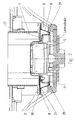
- the airbag housing 1 shown in Fig. 1 is designed so that it in can hold an airbag inside and from the outside into a receiving opening of one indicated only with its outline Motor vehicle steering wheel 2 can be inserted.
- the opening 4 is provided, in which the Airbag inflator 5 is inserted. So that the gas generator works can fulfill as a vibration damper, the opening 4 is kept larger than the diameter of the gas generator. Between the outer wall 6 of the Gas generator 5 and the edge 7 of the opening 4 is consequently one for the Vibrations of the gas generator 5 sufficient distance available.
- the gas generator 5 does not move the airbag during its swinging movements damaged and the oscillating movement of the gas generator 5 by the folded airbag are not hindered, it is from a cage 8 bordered.
- the cage 8 consists of individual ribs 9 with the free spaces 10, through which the gas can flow into the airbag.
- the openings 11 for the gas outlet from the Gas generator 5 attached In the wall 6 of the Gas generator 5 are the openings 11 for the gas outlet from the Gas generator 5 attached.
- the gas generator 5 is from the bottom completed by a pot-like base 12, the all-round Edge is designed as a mounting flange 13. In the mounting flange 13 there are several openings for screw connections 14 via which the gas generator 5 can be connected to the insert 15.
- the stake 15 consists essentially of the annular rubber membrane 16, the Adapter element 17 and the connecting plate 18.
- Rubber membrane 16, Adapter element 17 and connecting plate 18 are vulcanized connected with each other.
- the rubber membrane 16 is annular and runs longitudinally to the steering wheel axis 19.
- the structural design and Alignment of adapter element 17 and connecting plate 18 depends on the structural conditions in the steering wheel and the am Gas generator 5 and also existing on the airbag housing 1 Connectivity.
- the adapter element is 17th provided with openings that correspond to the openings of the mounting flange 13 correspond so that the fastening screws 14 are inserted can be. With its outer edge 20, the adapter element 17 is on vulcanized to the upper end 21 of the rubber membrane 16.
- the connecting plate 18 is connected to the airbag housing 1 via the screws 22 screwed on.
- the connecting plate 18 surrounds the airbag housing 1 and has the shape of a tube sheet.
- the connection plate has at its lower end 18 a shoulder 23 directed towards the steering wheel axis 19, on which the lower End 24 of the rubber membrane 16 is vulcanized.
- the rubber membrane 16 is frustoconical and the larger diameter of the The truncated cone points downwards.
- the insert 15 made of tubular sheet 25, Rubber membrane 16 and adapter element 17 is formed, and on Airbag housing 1 and gas generator 5 attached to the outside gastight seal is created. The gas generator 5 when triggered resulting gases cannot escape to the outside.
- the embodiment according to FIG. 2 corresponds in its basic Structure of the embodiment according to FIG. 1 as far as the airbag housing 1 and the gas generator 5 are affected.
- the insert 15 is designed differently.
- the adapter element 17 has according to the embodiment Fig. 1 shows an annular flange 27 which is aligned perpendicular to the steering wheel axis 19 is.
- the annular flange 27 is circumferential provided tubular extension 28, which projects radially outward Edge 29 has. With this edge 29, the lower end 24 is the Rubber membrane 16 connected by vulcanization.
- the upper end 21 of the Rubber membrane 16 connects to the connecting plate 18.
- the Connection plate 18 is aligned as perpendicular to the steering wheel axis 19 Ring flange 30 formed.
- a rotating Attachment flange 31 attached to which the ring flange 30 is screwed becomes.
- the connection between gas generator 5 and adapter element 17 is also done by screwing.
- the Rubber membrane 16 a truncated cone open further up.
Landscapes
- Engineering & Computer Science (AREA)
- Mechanical Engineering (AREA)
- Air Bags (AREA)
- Steering Controls (AREA)
- Steering-Linkage Mechanisms And Four-Wheel Steering (AREA)
Applications Claiming Priority (2)
| Application Number | Priority Date | Filing Date | Title |
|---|---|---|---|
| DE1999155427 DE19955427A1 (de) | 1999-11-18 | 1999-11-18 | Airbaggehäuse in einem Kraftfahrzeuglenkrad |
| DE19955427 | 1999-11-18 |
Publications (2)
| Publication Number | Publication Date |
|---|---|
| EP1101662A2 true EP1101662A2 (fr) | 2001-05-23 |
| EP1101662A3 EP1101662A3 (fr) | 2003-10-08 |
Family
ID=7929434
Family Applications (1)
| Application Number | Title | Priority Date | Filing Date |
|---|---|---|---|
| EP00121928A Withdrawn EP1101662A3 (fr) | 1999-11-18 | 2000-10-09 | Générateur de gaz pour coussin gonflable faisant effet d'amortisseur d'oscillations |
Country Status (3)
| Country | Link |
|---|---|
| EP (1) | EP1101662A3 (fr) |
| JP (1) | JP2001171460A (fr) |
| DE (1) | DE19955427A1 (fr) |
Cited By (6)
| Publication number | Priority date | Publication date | Assignee | Title |
|---|---|---|---|---|
| EP1314619A1 (fr) * | 2001-11-23 | 2003-05-28 | Firma Carl Freudenberg | Générateur de gaz d'un airbag de volant pour un vehicule automobile |
| EP1273488A3 (fr) * | 2001-07-06 | 2004-01-02 | Carl Freudenberg KG | Générateur de gas pour un airbag de volant |
| US7144034B2 (en) | 2004-02-18 | 2006-12-05 | Autoliv Asp, Inc. | Vibration damper gasket |
| US7246816B2 (en) * | 2003-03-21 | 2007-07-24 | Trw Automotive Safety Systems Gmbh | Gas bag module for a motor vehicle steering wheel |
| US7374199B2 (en) | 2005-04-04 | 2008-05-20 | Arc Automotive, Inc. | Air bag inflator vibration damper |
| US7494150B2 (en) | 2006-04-05 | 2009-02-24 | Arc Automotive, Inc. | Air bag inflator vibration damper |
Families Citing this family (3)
| Publication number | Priority date | Publication date | Assignee | Title |
|---|---|---|---|---|
| DE102009006077B4 (de) * | 2009-01-26 | 2015-04-02 | Autoliv Development Ab | Gassackeinheit |
| DE102010052325B4 (de) * | 2010-11-25 | 2017-03-16 | Vibracoustic Gmbh | Airbag-Tilger |
| KR101997363B1 (ko) * | 2017-12-11 | 2019-07-05 | 현대자동차주식회사 | 댐퍼 유동 강건화 조립 구조 |
Citations (3)
| Publication number | Priority date | Publication date | Assignee | Title |
|---|---|---|---|---|
| DE3925761A1 (de) | 1988-08-08 | 1990-02-15 | Honda Motor Co Ltd | Vibrationsunterdrueckungsvorrichtung fuer ein lenkrad mit einem luftsack |
| DE29816923U1 (de) | 1998-09-16 | 1998-11-26 | Petri Ag, 63743 Aschaffenburg | Lenkrad mit Airbagmodul |
| DE29902033U1 (de) | 1999-02-05 | 1999-04-08 | TRW Automotive Safety Systems GmbH, 63743 Aschaffenburg | Airbagmodul als Schwingungsdämpfer |
Family Cites Families (2)
| Publication number | Priority date | Publication date | Assignee | Title |
|---|---|---|---|---|
| DE4205726C3 (de) * | 1991-02-25 | 1999-04-29 | Trw Inc | Fahrzeuggassackmodul mit Koppelvorrichtung |
| DE19743615B4 (de) * | 1997-10-02 | 2006-02-02 | ZF Lemförder Metallwaren AG | Airbagbaueinheit |
-
1999
- 1999-11-18 DE DE1999155427 patent/DE19955427A1/de not_active Withdrawn
-
2000
- 2000-10-09 EP EP00121928A patent/EP1101662A3/fr not_active Withdrawn
- 2000-11-16 JP JP2000349661A patent/JP2001171460A/ja active Pending
Patent Citations (3)
| Publication number | Priority date | Publication date | Assignee | Title |
|---|---|---|---|---|
| DE3925761A1 (de) | 1988-08-08 | 1990-02-15 | Honda Motor Co Ltd | Vibrationsunterdrueckungsvorrichtung fuer ein lenkrad mit einem luftsack |
| DE29816923U1 (de) | 1998-09-16 | 1998-11-26 | Petri Ag, 63743 Aschaffenburg | Lenkrad mit Airbagmodul |
| DE29902033U1 (de) | 1999-02-05 | 1999-04-08 | TRW Automotive Safety Systems GmbH, 63743 Aschaffenburg | Airbagmodul als Schwingungsdämpfer |
Cited By (6)
| Publication number | Priority date | Publication date | Assignee | Title |
|---|---|---|---|---|
| EP1273488A3 (fr) * | 2001-07-06 | 2004-01-02 | Carl Freudenberg KG | Générateur de gas pour un airbag de volant |
| EP1314619A1 (fr) * | 2001-11-23 | 2003-05-28 | Firma Carl Freudenberg | Générateur de gaz d'un airbag de volant pour un vehicule automobile |
| US7246816B2 (en) * | 2003-03-21 | 2007-07-24 | Trw Automotive Safety Systems Gmbh | Gas bag module for a motor vehicle steering wheel |
| US7144034B2 (en) | 2004-02-18 | 2006-12-05 | Autoliv Asp, Inc. | Vibration damper gasket |
| US7374199B2 (en) | 2005-04-04 | 2008-05-20 | Arc Automotive, Inc. | Air bag inflator vibration damper |
| US7494150B2 (en) | 2006-04-05 | 2009-02-24 | Arc Automotive, Inc. | Air bag inflator vibration damper |
Also Published As
| Publication number | Publication date |
|---|---|
| EP1101662A3 (fr) | 2003-10-08 |
| JP2001171460A (ja) | 2001-06-26 |
| DE19955427A1 (de) | 2001-06-07 |
Similar Documents
| Publication | Publication Date | Title |
|---|---|---|
| EP1113948B2 (fr) | Volant pourvu d'un sac gonflable | |
| EP1026050B1 (fr) | Module de coussin gonflable amortisseur de vibrations | |
| DE19712228A1 (de) | Befestigungsvorrichtung für einen Gebläsemotor | |
| EP1101663A2 (fr) | Générateur de gaz pour coussin de sécurité faisant effet d'amortisseur d'oscillations | |
| DE4310173C2 (de) | Airbagmodul | |
| DE19840998A1 (de) | Airbaganordnung bei Fahrzeugen | |
| EP1101662A2 (fr) | Générateur de gaz pour coussin gonflable faisant effet d'amortisseur d'oscillations | |
| DE19581552B4 (de) | Lenkrad mit vormontiertem Airbagmodul | |
| DE3537865A1 (de) | Zweikammer-stuetzlager mit hydraulischer daempfung | |
| EP3209525A1 (fr) | Module airbag, diffuseur pour un module airbag et système de sécurité d'occupants de véhicule | |
| DE10156424B4 (de) | Luftsackmodul für Kraftfahrzeuge | |
| DE2416512A1 (de) | Vibrator | |
| EP1270340A2 (fr) | Module de coussin gonflable avec générateur de gaz servant de masse d'atténuation de vibrations | |
| DE10002480B4 (de) | Airbagmodul für ein Kraftfahrzeuglenkrad | |
| DE102007049234B4 (de) | Airbagmodul für ein Kraftfahrzeug | |
| DE4102615C2 (fr) | ||
| EP1238869A1 (fr) | Générateur de gaz pour coussin gonflable sur un volant de véhicule automobile | |
| DE202011108508U1 (de) | Airbag für ein Fahrzeug insbesondere Kraftfahrzeug | |
| DE10110912B4 (de) | Airbagmodul für ein Lenkrad eines Kraftfahrzeugs | |
| DE10311465A1 (de) | Airbaggehäuse an einem Kraftfahrzeuglenkrad mit einem Gasgenerator als Tilgermasse | |
| EP1273488B1 (fr) | Générateur de gas pour un airbag de volant | |
| DE19616940C1 (de) | Beifahrer-Airbag-Modul | |
| DE19648137C2 (de) | Airbagmodul | |
| DE20104044U1 (de) | Gassack-Modul | |
| DE10349458B4 (de) | Airbagmodul mit einem am Diffusor gehalterten Gasgenerator |
Legal Events
| Date | Code | Title | Description |
|---|---|---|---|
| PUAI | Public reference made under article 153(3) epc to a published international application that has entered the european phase |
Free format text: ORIGINAL CODE: 0009012 |
|
| AK | Designated contracting states |
Kind code of ref document: A2 Designated state(s): AT BE CH CY DE DK ES FI FR GB GR IE IT LI LU MC NL PT SE |
|
| AX | Request for extension of the european patent |
Free format text: AL;LT;LV;MK;RO;SI |
|
| RAP1 | Party data changed (applicant data changed or rights of an application transferred) |
Owner name: CARL FREUDENBERG KG |
|
| PUAL | Search report despatched |
Free format text: ORIGINAL CODE: 0009013 |
|
| AK | Designated contracting states |
Kind code of ref document: A3 Designated state(s): AT BE CH CY DE DK ES FI FR GB GR IE IT LI LU MC NL PT SE |
|
| AX | Request for extension of the european patent |
Extension state: AL LT LV MK RO SI |
|
| AKX | Designation fees paid | ||
| REG | Reference to a national code |
Ref country code: DE Ref legal event code: 8566 |
|
| STAA | Information on the status of an ep patent application or granted ep patent |
Free format text: STATUS: THE APPLICATION IS DEEMED TO BE WITHDRAWN |
|
| 18D | Application deemed to be withdrawn |
Effective date: 20040504 |