EP1101856A2 - Enclume pour dispositif de coupe ultrasonique - Google Patents
Enclume pour dispositif de coupe ultrasonique Download PDFInfo
- Publication number
- EP1101856A2 EP1101856A2 EP00124660A EP00124660A EP1101856A2 EP 1101856 A2 EP1101856 A2 EP 1101856A2 EP 00124660 A EP00124660 A EP 00124660A EP 00124660 A EP00124660 A EP 00124660A EP 1101856 A2 EP1101856 A2 EP 1101856A2
- Authority
- EP
- European Patent Office
- Prior art keywords
- anvil
- cradle
- anvil assembly
- assembly according
- engagement
- Prior art date
- Legal status (The legal status is an assumption and is not a legal conclusion. Google has not performed a legal analysis and makes no representation as to the accuracy of the status listed.)
- Withdrawn
Links
Images


Classifications
-
- B—PERFORMING OPERATIONS; TRANSPORTING
- B29—WORKING OF PLASTICS; WORKING OF SUBSTANCES IN A PLASTIC STATE IN GENERAL
- B29C—SHAPING OR JOINING OF PLASTICS; SHAPING OF MATERIAL IN A PLASTIC STATE, NOT OTHERWISE PROVIDED FOR; AFTER-TREATMENT OF THE SHAPED PRODUCTS, e.g. REPAIRING
- B29C65/00—Joining or sealing of preformed parts, e.g. welding of plastics materials; Apparatus therefor
- B29C65/02—Joining or sealing of preformed parts, e.g. welding of plastics materials; Apparatus therefor by heating, with or without pressure
- B29C65/08—Joining or sealing of preformed parts, e.g. welding of plastics materials; Apparatus therefor by heating, with or without pressure using ultrasonic vibrations
-
- B—PERFORMING OPERATIONS; TRANSPORTING
- B26—HAND CUTTING TOOLS; CUTTING; SEVERING
- B26D—CUTTING; DETAILS COMMON TO MACHINES FOR PERFORATING, PUNCHING, CUTTING-OUT, STAMPING-OUT OR SEVERING
- B26D7/00—Details of apparatus for cutting, cutting-out, stamping-out, punching, perforating, or severing by means other than cutting
- B26D7/08—Means for treating work or cutting member to facilitate cutting
- B26D7/086—Means for treating work or cutting member to facilitate cutting by vibrating, e.g. ultrasonically
-
- B—PERFORMING OPERATIONS; TRANSPORTING
- B29—WORKING OF PLASTICS; WORKING OF SUBSTANCES IN A PLASTIC STATE IN GENERAL
- B29C—SHAPING OR JOINING OF PLASTICS; SHAPING OF MATERIAL IN A PLASTIC STATE, NOT OTHERWISE PROVIDED FOR; AFTER-TREATMENT OF THE SHAPED PRODUCTS, e.g. REPAIRING
- B29C65/00—Joining or sealing of preformed parts, e.g. welding of plastics materials; Apparatus therefor
- B29C65/74—Joining or sealing of preformed parts, e.g. welding of plastics materials; Apparatus therefor by welding and severing, or by joining and severing, the severing being performed in the area to be joined, next to the area to be joined, in the joint area or next to the joint area
- B29C65/743—Joining or sealing of preformed parts, e.g. welding of plastics materials; Apparatus therefor by welding and severing, or by joining and severing, the severing being performed in the area to be joined, next to the area to be joined, in the joint area or next to the joint area using the same tool for both joining and severing, said tool being monobloc or formed by several parts mounted together and forming a monobloc
- B29C65/7443—Joining or sealing of preformed parts, e.g. welding of plastics materials; Apparatus therefor by welding and severing, or by joining and severing, the severing being performed in the area to be joined, next to the area to be joined, in the joint area or next to the joint area using the same tool for both joining and severing, said tool being monobloc or formed by several parts mounted together and forming a monobloc by means of ultrasonic vibrations
-
- B—PERFORMING OPERATIONS; TRANSPORTING
- B29—WORKING OF PLASTICS; WORKING OF SUBSTANCES IN A PLASTIC STATE IN GENERAL
- B29C—SHAPING OR JOINING OF PLASTICS; SHAPING OF MATERIAL IN A PLASTIC STATE, NOT OTHERWISE PROVIDED FOR; AFTER-TREATMENT OF THE SHAPED PRODUCTS, e.g. REPAIRING
- B29C66/00—General aspects of processes or apparatus for joining preformed parts
- B29C66/70—General aspects of processes or apparatus for joining preformed parts characterised by the composition, physical properties or the structure of the material of the parts to be joined; Joining with non-plastics material
- B29C66/72—General aspects of processes or apparatus for joining preformed parts characterised by the composition, physical properties or the structure of the material of the parts to be joined; Joining with non-plastics material characterised by the structure of the material of the parts to be joined
- B29C66/729—Textile or other fibrous material made from plastics
-
- B—PERFORMING OPERATIONS; TRANSPORTING
- B29—WORKING OF PLASTICS; WORKING OF SUBSTANCES IN A PLASTIC STATE IN GENERAL
- B29C—SHAPING OR JOINING OF PLASTICS; SHAPING OF MATERIAL IN A PLASTIC STATE, NOT OTHERWISE PROVIDED FOR; AFTER-TREATMENT OF THE SHAPED PRODUCTS, e.g. REPAIRING
- B29C66/00—General aspects of processes or apparatus for joining preformed parts
- B29C66/80—General aspects of machine operations or constructions and parts thereof
- B29C66/81—General aspects of the pressing elements, i.e. the elements applying pressure on the parts to be joined in the area to be joined, e.g. the welding jaws or clamps
- B29C66/816—General aspects of the pressing elements, i.e. the elements applying pressure on the parts to be joined in the area to be joined, e.g. the welding jaws or clamps characterised by the mounting of the pressing elements, e.g. of the welding jaws or clamps
- B29C66/8167—Quick change joining tools or surfaces
-
- B—PERFORMING OPERATIONS; TRANSPORTING
- B29—WORKING OF PLASTICS; WORKING OF SUBSTANCES IN A PLASTIC STATE IN GENERAL
- B29C—SHAPING OR JOINING OF PLASTICS; SHAPING OF MATERIAL IN A PLASTIC STATE, NOT OTHERWISE PROVIDED FOR; AFTER-TREATMENT OF THE SHAPED PRODUCTS, e.g. REPAIRING
- B29C66/00—General aspects of processes or apparatus for joining preformed parts
- B29C66/80—General aspects of machine operations or constructions and parts thereof
- B29C66/83—General aspects of machine operations or constructions and parts thereof characterised by the movement of the joining or pressing tools
- B29C66/832—Reciprocating joining or pressing tools
- B29C66/8322—Joining or pressing tools reciprocating along one axis
-
- D—TEXTILES; PAPER
- D06—TREATMENT OF TEXTILES OR THE LIKE; LAUNDERING; FLEXIBLE MATERIALS NOT OTHERWISE PROVIDED FOR
- D06H—MARKING, INSPECTING, SEAMING OR SEVERING TEXTILE MATERIALS
- D06H7/00—Apparatus or processes for cutting, or otherwise severing, specially adapted for the cutting, or otherwise severing, of textile materials
- D06H7/22—Severing by heat or by chemical agents
- D06H7/221—Severing by heat or by chemical agents by heat
- D06H7/223—Severing by heat or by chemical agents by heat using ultrasonic vibration
-
- B—PERFORMING OPERATIONS; TRANSPORTING
- B29—WORKING OF PLASTICS; WORKING OF SUBSTANCES IN A PLASTIC STATE IN GENERAL
- B29C—SHAPING OR JOINING OF PLASTICS; SHAPING OF MATERIAL IN A PLASTIC STATE, NOT OTHERWISE PROVIDED FOR; AFTER-TREATMENT OF THE SHAPED PRODUCTS, e.g. REPAIRING
- B29C66/00—General aspects of processes or apparatus for joining preformed parts
- B29C66/70—General aspects of processes or apparatus for joining preformed parts characterised by the composition, physical properties or the structure of the material of the parts to be joined; Joining with non-plastics material
- B29C66/73—General aspects of processes or apparatus for joining preformed parts characterised by the composition, physical properties or the structure of the material of the parts to be joined; Joining with non-plastics material characterised by the intensive physical properties of the material of the parts to be joined, by the optical properties of the material of the parts to be joined, by the extensive physical properties of the parts to be joined, by the state of the material of the parts to be joined or by the material of the parts to be joined being a thermoplastic or a thermoset
- B29C66/739—General aspects of processes or apparatus for joining preformed parts characterised by the composition, physical properties or the structure of the material of the parts to be joined; Joining with non-plastics material characterised by the intensive physical properties of the material of the parts to be joined, by the optical properties of the material of the parts to be joined, by the extensive physical properties of the parts to be joined, by the state of the material of the parts to be joined or by the material of the parts to be joined being a thermoplastic or a thermoset characterised by the material of the parts to be joined being a thermoplastic or a thermoset
- B29C66/7392—General aspects of processes or apparatus for joining preformed parts characterised by the composition, physical properties or the structure of the material of the parts to be joined; Joining with non-plastics material characterised by the intensive physical properties of the material of the parts to be joined, by the optical properties of the material of the parts to be joined, by the extensive physical properties of the parts to be joined, by the state of the material of the parts to be joined or by the material of the parts to be joined being a thermoplastic or a thermoset characterised by the material of the parts to be joined being a thermoplastic or a thermoset characterised by the material of at least one of the parts being a thermoplastic
- B29C66/73921—General aspects of processes or apparatus for joining preformed parts characterised by the composition, physical properties or the structure of the material of the parts to be joined; Joining with non-plastics material characterised by the intensive physical properties of the material of the parts to be joined, by the optical properties of the material of the parts to be joined, by the extensive physical properties of the parts to be joined, by the state of the material of the parts to be joined or by the material of the parts to be joined being a thermoplastic or a thermoset characterised by the material of the parts to be joined being a thermoplastic or a thermoset characterised by the material of at least one of the parts being a thermoplastic characterised by the materials of both parts being thermoplastics
-
- B—PERFORMING OPERATIONS; TRANSPORTING
- B29—WORKING OF PLASTICS; WORKING OF SUBSTANCES IN A PLASTIC STATE IN GENERAL
- B29C—SHAPING OR JOINING OF PLASTICS; SHAPING OF MATERIAL IN A PLASTIC STATE, NOT OTHERWISE PROVIDED FOR; AFTER-TREATMENT OF THE SHAPED PRODUCTS, e.g. REPAIRING
- B29C66/00—General aspects of processes or apparatus for joining preformed parts
- B29C66/80—General aspects of machine operations or constructions and parts thereof
- B29C66/81—General aspects of the pressing elements, i.e. the elements applying pressure on the parts to be joined in the area to be joined, e.g. the welding jaws or clamps
- B29C66/818—General aspects of the pressing elements, i.e. the elements applying pressure on the parts to be joined in the area to be joined, e.g. the welding jaws or clamps characterised by the cooling constructional aspects, or by the thermal or electrical insulating or conducting constructional aspects of the welding jaws or of the clamps ; comprising means for compensating for the thermal expansion of the welding jaws or of the clamps
- B29C66/8187—General aspects of the pressing elements, i.e. the elements applying pressure on the parts to be joined in the area to be joined, e.g. the welding jaws or clamps characterised by the cooling constructional aspects, or by the thermal or electrical insulating or conducting constructional aspects of the welding jaws or of the clamps ; comprising means for compensating for the thermal expansion of the welding jaws or of the clamps characterised by the electrical insulating constructional aspects
- B29C66/81871—General aspects of the pressing elements, i.e. the elements applying pressure on the parts to be joined in the area to be joined, e.g. the welding jaws or clamps characterised by the cooling constructional aspects, or by the thermal or electrical insulating or conducting constructional aspects of the welding jaws or of the clamps ; comprising means for compensating for the thermal expansion of the welding jaws or of the clamps characterised by the electrical insulating constructional aspects of the welding jaws
-
- B—PERFORMING OPERATIONS; TRANSPORTING
- B29—WORKING OF PLASTICS; WORKING OF SUBSTANCES IN A PLASTIC STATE IN GENERAL
- B29C—SHAPING OR JOINING OF PLASTICS; SHAPING OF MATERIAL IN A PLASTIC STATE, NOT OTHERWISE PROVIDED FOR; AFTER-TREATMENT OF THE SHAPED PRODUCTS, e.g. REPAIRING
- B29C66/00—General aspects of processes or apparatus for joining preformed parts
- B29C66/80—General aspects of machine operations or constructions and parts thereof
- B29C66/82—Pressure application arrangements, e.g. transmission or actuating mechanisms for joining tools or clamps
- B29C66/824—Actuating mechanisms
- B29C66/8242—Pneumatic or hydraulic drives
-
- B—PERFORMING OPERATIONS; TRANSPORTING
- B29—WORKING OF PLASTICS; WORKING OF SUBSTANCES IN A PLASTIC STATE IN GENERAL
- B29L—INDEXING SCHEME ASSOCIATED WITH SUBCLASS B29C, RELATING TO PARTICULAR ARTICLES
- B29L2031/00—Other particular articles
- B29L2031/744—Labels, badges, e.g. marker sleeves
-
- Y—GENERAL TAGGING OF NEW TECHNOLOGICAL DEVELOPMENTS; GENERAL TAGGING OF CROSS-SECTIONAL TECHNOLOGIES SPANNING OVER SEVERAL SECTIONS OF THE IPC; TECHNICAL SUBJECTS COVERED BY FORMER USPC CROSS-REFERENCE ART COLLECTIONS [XRACs] AND DIGESTS
- Y10—TECHNICAL SUBJECTS COVERED BY FORMER USPC
- Y10T—TECHNICAL SUBJECTS COVERED BY FORMER US CLASSIFICATION
- Y10T156/00—Adhesive bonding and miscellaneous chemical manufacture
- Y10T156/12—Surface bonding means and/or assembly means with cutting, punching, piercing, severing or tearing
- Y10T156/1313—Cutting element simultaneously bonds [e.g., cut seaming]
Definitions
- the present invention relates to a textile-cutting device, in particular for cutting and sealing textile tape, and more specifically with reference to an anvil construction for an ultrasonic cutting apparatus.
- an ultrasonic wave generator comprises a horn, which is vibrated by the generator against the peaked cutting edge of an anvil, thereby cutting a strip of material disposed therebetween.
- textile material is either thermoplastic or comprises a thermoplastic fiber content.
- a roll of continuous printed labels is cut into individual labels using ultrasonic energy prior to stitching the cut labels onto garments.
- each label may be folded in two prior to being stitched to the garment, or, alternatively, the label strip may be folded just prior to the cutting operation such that as each label is cut, the upstream and downstream cut edges are fused together.
- the horn As the horn is vibrated against the anvil, for example at a frequency of about 30 to about 40 KHz, the horn undergoes at its output surface a small translation in peak-to-peak amplitude. At these conditions, large acceleration forces (typically of the order of several thousand g) are induced, and corresponding forces cause the horn. which is urged against the anvil, to be repetitively impacted and driven away from the anvil, thereby enabling a strip of material to be cut when disposed in-between the anvil and the horn. The anvil is thus subjected to severe vibration and impact forces, particularly on the edge thereof, which thus becomes worn rather quickly with use.
- large acceleration forces typically of the order of several thousand g
- the present invention provides an anvil construction comprising an anvil lockably mountable onto a cradle in one of at least two interchangeable mounting positions. Corresponding to each mounting position, the anvil has at least one longitudinal cutting edge and a corresponding engagement section for engagement with a complementary engagement means formed in the cradle.
- anvil assembly adapted for selective cooperation with a horn operatively connected to an ultrasonic wave generator such as to enable a textile workpiece disposed between said horn and said anvil assembly to be cut with the cut and simultaneously sealed.
- the anvil assembly comprises an anvil and a cradle, said anvil adapted to be selectively mounted onto the cradle in any one of at least two mounting positions.
- said anvil comprises one peaked longitudinal cutting edge and a corresponding engagement section substantially parallel to a longitudinal axis of the anvil; said corresponding positioning and engagement section adapted for selective engagement with a complementary engagement means enabling said anvil assembly to be removably positioned and locked onto said cradle in a corresponding one of said at least two mounting positions such as to enable said peaked edge corresponding to said one of said at least two mounting positions to protrude from said cradle.
- the engagement means comprise at least one abutment member which abuts the anvil against a complementary engaging surface of the cradle.
- the engagement surface may be in the form of a receptacle or a projection, formed of one or more wall portions, which together with the abutment member provide positioning and fixation means.
- the anvil is in the form of an elongate prism-like member having a nominally constant transverse cross-sectional profile along its longitudinal axis, and comprising a plurality of longitudinal cutting edges, angularly spaced one from another with respect to the longitudinal axis of the anvil.
- the prism-like member is locked onto the cradle by means of said engagement means, in any one of a plurality of angular positions, the number of angular positions being correlated to the number of parallel edges of the prism, such that in each position one cutting edge is in turn brought into registry with the horn of the ultrasonic generator.
- the prism is removed from the cradle, rotated about its axis and replaced in the cradle such that a new edge is aligned with the horn.
- the anvil according to the present invention may also be designed for incorporation in a cradle that is retrofittable with respect to existing ultrasonic cutting machines.
- the ultrasonic tape cutting apparatus comprises an anvil assembly generally designated 10 , vertically aligned with horn 52 of an ultrasonic wave generator 50 .
- the generator 50 is carried on a shaft 60 that is reciprocally shiftable along the axis 200 thereof, by any suitable means such as a pneumatic actuator 70 or the like.
- the actuator 70 and the anvil assembly 10 are mounted at opposed ends of a support frame 80 such that, as the actuator 70 is actuated, the horn 50 may be selectively brought into contact with and separated from the anvil assembly 10 as desired, in particular with respect to the protruding cutting edge 32 thereof, as will be described hereinafter.
- a roll 90 (Fig. 2) holds a continuous textile strip 99 . comprising, for example, pre-printed labels for clothing, is fed to the device 100 by upstream parallel feed rollers 94 and 96 .
- An optical scanner 98 scans the strip 99 as it passes the downstream edge 95 of a presser plate 97 . which maintains the strip 99 flat and pressed against the table 93 .
- the scanner 98 is operatively connected to a controller (not shown). typically a microprocessor. and enables the tape 99 to be fed in a synchronized manner to the cutting station 150 of the device 100 . such that strip 99 is cut into individual labels at the correct upstream and downstream portions of each label.
- the cutting apparatus 100 may optionally further comprise folding means to fold each portion of the strip 99 corresponding to an individual label into two, prior to the same being cut, such that the upstream and downstream edges of each individual label are fused together as it is cut from the strip 99 .
- folding means are known in the art.
- each individual label may be folded in two after the cutting operation, in a separate folding operation downstream thereof, prior to, or in conjunction with stitching of the label to a garment.
- a preferred embodiment of the anvil assembly 10 comprises a longitudinal cradle 20 which replaceably supports the anvil in its respective operative positions, as will become apparent hereinafter.
- the cradle 20 is formed with an engagement means, which in the present embodiment is in the form of a receptacle recess or longitudinal slot 22 along at least part of its axial or longitudinal length on the upper surface 21 of the cradle 20 .
- the slot 22 is adapted for laterally receiving and engaging an anvil 30 .
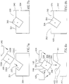
- the anvil 30 has, in the preferred embodiment, a square cross-sectional transverse profile, with four longitudinal parallel peaked cutting edges 32 . each edge 32 angularly arranged at 90° with respect to adjacent edges 32 .
- the slot 22 has a rectangular transverse profile, having sides angled at 45° to the upper surface 21 of the cradle 20 , as illustrated in Fig. 3 and Fig. 5.
- the anvil 30 may be laterally received into said slot 22 in any one of four mounting positions of the anvil 30 .
- the mounting positions are angularly displaced one from another along planes perpendicular to the longitudinal axis of the anvil 30 .
- one of the said four edges 32 say edge 32A (see Fig. 5a). protrudes from the upper surface 21 of the cradle 20 .
- surfaces 141 and 142 of the anvil 30 extend in respective opposite directions from another edge 32C disposed at 180° from said edge 32A .
- the surfaces 141 and 142 are examples of the anvil 30 .
- the receptacle slot 22 further comprises a longitudinal surface 147 adapted for abutment against a respective surface 145 the said anvil 30 .
- the cradle 20 further comprises a surface 26 angled with respect to the upper surface 21 of cradle 20 such that it is coplanar with the longitudinal planar surfaces 146 , of the anvil 20 when received within slot 22 .
- the anvil 30 is positioned and locked in the slot 22 by locking bracket 40 formed in a generally prismatic shape, having a substantially triangular transverse profile, which when assembled has at least one substantially planar wall 42 extending axially in parallel arrangement to said slot 22.
- the wall 42 of the bracket 40 comprises at a longitudinal portion 48 adapted for abutting against a longitudinal portion of wall 146 of the anvil 30 .
- surface 48 is at about 45° to the upper surface 21 .
- the bracket 40 is secured to the cradle 20 by any suitable means such as bolts 44 (Fig. 3) or the like, such that with at least part of surface 26 being in contact with wall 42 , portion 48 of said wall 42 secures and locks the anvil 30 within the slot 22 .
- the bracket 30 may be secured in its abutting position also by suitable clamping means, as known per se.
- the anvil 30 When the protruding cutting edge 32A becomes worn, the anvil 30 may be removed from the slot, turned by 90° or multiple thereof about its longitudinal axis. and reinserted into the slot 22 such that a different edge 32 now becomes the protruding, active edge.
- the cradle 220 comprises a V-shaped slot 222 , formed of surfaces 143 and 144 preferably extending in a lateral direction to a similar extent as the surfaces 141 and 142 of the anvil 30 . Nonetheless, surfaces 143 and 144 , respectively may extend in a lateral direction to a lesser or to a greater extent as the surfaces 141 and 142 . respectively, in which case the upper surface 224 of the cradle 220 would be lower or higher, respectively, than the lateral edges indicated at 32B and 32D of the anvil 30 , in Figs. 6a and 6b.
- Anvil 30 is placed and locked onto the cradle 220 by two brackets 240 in parallel arrangement disposed on either side of the anvil 30 .
- Each bracket 240 comprises a surface 241 for abutting against corresponding surfaces 145 and 146 . of the anvil 30 .
- the brackets are secured to the anvil by suitable bolts, not shown.
- the two locking brackets 240 may be removed from the cradle 20 , and the anvil 30 may then be extracted from the slot 222 , turned about its axis by 90° or 180° or 270°, and reinserted into the slot 222 , such as to expose a different edge 32 protruding on upper surface 224 .
- the anvil 30 of the first and second embodiment comprises a substantially square transverse cross-section, having four planes of symmetry parallel to the axis of the anvil 30 . Nonetheless, it is also possible to have a substantially rectangular cross-sectional profile, with two planes of symmetry, in which case such an anvil only has two mounting positions with respect to the second engagement means.
- the said anvil may comprise a cross-sectional shape having no planes of symmetry, for example a parallelepiped having one pair of opposed sides smaller than the second pair of opposed sides, with one pair of opposed angles being acute, while the other pair of opposed angles being obtuse.
- the anvil 300 has a transverse cross-section in the shape of a non-symmetrical parallelogram instead of a square as in the previous embodiments.
- the anvil 300 can be selectively mounted onto the cradle 304 in any one of only two positions, enabling one or other of the acute edges 332A or 332C to protrude from the upper surface 324 of the cradle 20 . Nonetheless, by rotating the anvil 300 by 180° about an axis perpendicular to its longitudinal axis, either one of the obtuse edges 332B or 332D my be configured to protrude from upper surface 338 .
- a single bracket 340 releasably locks the anvil 300 in position in the cradle 304 , such that an edge 332A protrudes from an upper surface 338 of bracket 340 .
- engagement means of the cradle 342 comprises a V-shaped slot 422 , comprising surfaces 143 and 144 which in this embodiment are of different transverse lengths but extend in a lateral direction to a similar extent as the surfaces 346 and 348, respectively, of the anvil 300.
- the anvil 300 is lockable in the receptacle slot 422 by two brackets 424 and 425 in parallel arrangement disposed on either side of the anvil 300.
- Each bracket comprises a surface 441 and 442 , respectively for abutting against surfaces 145 and 146 , of the anvil 300 for locking the anvil 300 in place when the same is engaged in the cradle 342 .
- edge 32A protrudes from equi-leveled upper surfaces 350 and 352 of brackets 424 and 425 , respectively.
- the anvil may have a regular convex polygonal or star-shaped transverse profile comprising a plurality, say “ n “, substantially identical vertices, with a corresponding receptacle slot adapted to receive the anvil in any one of " n “ positions, wherein each position is angularly displaced from adjacent positions by 360°/n.
- the cutting edge may be replaced n times using a similar. procedure to that described for the preferred embodiment, mutatis mutandis.
- a fifth embodiment of the present invention illustrated in Figs. 9a and 9b, comprises the same structural elements as the previous embodiments, with the difference that the anvil 358 has a transverse cross-section in the shape of an equilateral triangle instead of a square, and thus comprises three longitudinal cutting edges 532 .
- the engagement means is in the shape of a V-shaped slot 522 complementary to surfaces 541 and 542 of the anvil 358 .
- a bracket 524 releasably locks the anvil 358 in position in the cradle 356 with an edge 532A protruding from a top surface 360 of the cradle 356 , which in the present example, surface 360 is equi-leveled with a corresponding top surface 362 of bracket 524 .
- the anvil 380 has a transverse cross-section in the shape of regular pentagon, and thus comprises five longitudinal cutting edges 632 , with one of these edges 632 , say edge 632A , protruding from a top surface 368 of the cradle 366 .
- a bracket 624 comprises two engaging/abutting surfaces 648 and 649 to lock the anvil in place by pressing against the corresponding surfaces 646 and 699 , respectively of the anvil and respective surfaces 372 , 374 and 376 of the cradle 366 , forming together the engagement means.
- Figs. 11a and 11b illustrate still a further embodiment in which the anvil 380 has a transverse cross-section in the shape of regular five pointed star, and thus comprises five longitudinal cutting edges 732A to 732E , with one of these edges 732, say edge 732A , protruding from the cradle 382 .
- the engagement means comprises a V-shaped slot 384 formed on an inclined surface 386 , complementary to surfaces 741 , 742 respectively, which are comprised on the fourth edge 732D clockwise from the protruding edge 732A as illustrated in Fig. 11a.
- the bracket 724 comprises surfaces abutting 748 and 749 complementary to surfaces 174B and 174A to lock the anvil 380 in said cradle 20 , such that edge 732A protrudes from an upper surface 388 of the cradle 382 .
- each of the embodiments of anvils respectively illustrated in Figs. 9, 10 and 11 may be configured with two locking brackets, rather than a single locking bracket, in a similar manner to that described herein with reference to the first and second embodiments, mutatis mutandis.
- the anvil 358 is fixed to the cradle 390 by two abutting brackets 824 and 825 ;
- the anvil 364 is fixed to the cradle 392 by two abutting brackets 924 and 925 ;
- the anvil 380 is fixed to the cradle 394 by two abutting brackets 1024 and 1025 , respectively.
- the horn 52 may be arranged to be in registry with a longitudinal portion of the anvil extending between one end thereof and the middle of its longitudinal length.
- the horn 52 may be arranged to be in registry with a longitudinal portion of the anvil extending between one end thereof and the middle of its longitudinal length.
- each cutting edge may be, in turn, brought into registry with the horn 52 .
- anvils having a single plane of symmetry for example comprising a transverse cross-sectional profile of an isosceles triangle or of a trapezium, to be used in two mounting positions.
- the anvil assembly 10 is assembled by laterally inserting anvil 30 into slot 22 of the cradle 20 , and secured and locked therein by means of bracket 40 , allowing one edge 32 to protrude with respect to upper surface 21 .
- the anvil assembly 10 is then mounted onto the frame 80 by suitable means such as screws 88 , such that the edge 32 , preferably only up to half the longitudinal length thereof, is vertically aligned with the impact surface 53 of horn 52 .
- Slots 86 may be suitable shaped such as to allow some aligning adjustments of the cradle 20 to be made with respect to frame 80 , particularly when part of the exposed edge 32 becomes worn and goes out of alignment with respect to impact surface 53 .
- Actuator 70 retracts the horn 52 from the edge 32 leaving a suitable clearance therebetween at the cutting station 150 , such that the rollers 92 , 94 may advance a suitable length of strip 99 past the cutting station 150 , corresponding to an individual label.
- the actuator 70 then urges the horn 52 towards the edge 32 such as to sandwich therebetween a portion of the strip 99 , and the ultrasonic wave generator 50 then vibrates the horn 52 against the edge 32 severing the strip 99 thereat and thereby cutting an individual label, and eventually bringing the horn 52 into contact with the anvil assembly 10 .
- contact between the horn and the anvil completes an electrical circuit, which is set up to enable the actuator 70 to retract the horn 52 from the edge 32 at that point, thereby breaking the circuit, in which case the anvil assembly 10 is electrically insulated from the frame 80 at its mutual mounting point.
- the breaking of the circuit enables another length of tape 99 to he advanced past the cutting station 150 , and the horn 52 is again brought into contact with a new part of the tape. This procedure is repeated for each individual label cut by the cutting apparatus 100 .
- the same arrangement applies for the other embodiments, mutatis mutandis.
Landscapes
- Engineering & Computer Science (AREA)
- Mechanical Engineering (AREA)
- Textile Engineering (AREA)
- Life Sciences & Earth Sciences (AREA)
- Forests & Forestry (AREA)
- Treatment Of Fiber Materials (AREA)
- Perforating, Stamping-Out Or Severing By Means Other Than Cutting (AREA)
Applications Claiming Priority (2)
| Application Number | Priority Date | Filing Date | Title |
|---|---|---|---|
| IL13289399 | 1999-11-11 | ||
| IL13289399A IL132893A (en) | 1999-11-11 | 1999-11-11 | Anvil for ultrasonic cutting apparatus |
Publications (2)
| Publication Number | Publication Date |
|---|---|
| EP1101856A2 true EP1101856A2 (fr) | 2001-05-23 |
| EP1101856A3 EP1101856A3 (fr) | 2001-08-08 |
Family
ID=11073468
Family Applications (1)
| Application Number | Title | Priority Date | Filing Date |
|---|---|---|---|
| EP00124660A Withdrawn EP1101856A3 (fr) | 1999-11-11 | 2000-11-10 | Enclume pour dispositif de coupe ultrasonique |
Country Status (6)
| Country | Link |
|---|---|
| US (1) | US6637490B1 (fr) |
| EP (1) | EP1101856A3 (fr) |
| JP (1) | JP2001214363A (fr) |
| CN (1) | CN1297082A (fr) |
| IL (1) | IL132893A (fr) |
| TW (1) | TW550164B (fr) |
Cited By (7)
| Publication number | Priority date | Publication date | Assignee | Title |
|---|---|---|---|---|
| EP1745915A1 (fr) * | 2005-07-22 | 2007-01-24 | Rovema Verpackungsmaschinen GmbH | Dispositif pour souder des thermoplastiques |
| EP1354693A3 (fr) * | 2002-03-30 | 2008-08-27 | Herrmann Ultraschalltechnik GmbH & Co. KG | Procédé pour le soudage par ultrasons de pièces à paroi mince |
| GB2472760A (en) * | 2009-04-25 | 2011-02-23 | Ceetak Ltd | Anvil for use in heat sealing and cutting of plastic films |
| WO2014147369A1 (fr) * | 2013-03-19 | 2014-09-25 | Ceetak Ltd | Appareil pour couper et sceller une matière plastique |
| FR3097352A1 (fr) * | 2019-06-17 | 2020-12-18 | Fenotag | Ensemble d’étiquettes électroniques de radio-identification, procédé de fabrication dudit ensemble, machine utilisant ledit ensemble et produit textile comportant une étiquette électronique |
| EP3848186A1 (fr) * | 2020-01-08 | 2021-07-14 | Ecolean AB | Élément de scellage pour sceller un emballage et dispositif pour sceller un emballage |
| RU2795032C1 (ru) * | 2020-01-08 | 2023-04-27 | Эколин Аб | Запечатывающий элемент для герметизации упаковки и устройство для герметизации упаковки |
Families Citing this family (10)
| Publication number | Priority date | Publication date | Assignee | Title |
|---|---|---|---|---|
| ATE358862T1 (de) * | 2001-05-15 | 2007-04-15 | Pittsfield Weaving Co Inc | Verfahren und vorrichtung zur herstellung von rf- etiketten |
| US20040238098A1 (en) * | 2002-05-14 | 2004-12-02 | Bleckmann Frederick August | Method and apparatus for production of RF labels |
| US8495943B2 (en) | 2004-04-22 | 2013-07-30 | The Boeing Company | Anvil for supporting cuts in sheet and roll stock |
| US7724144B2 (en) * | 2004-12-30 | 2010-05-25 | Pittsfield Weaving Co., Inc. | Label having a cavity for receiving a RFID device and an apparatus and method of making and assembling the same |
| US7858164B2 (en) | 2006-04-03 | 2010-12-28 | Federal-Mogul World Wide, Inc. | End fray solution for textile structure |
| JP4264123B1 (ja) * | 2008-12-01 | 2009-05-13 | 朋和産業株式会社 | 切断補助線形成方法 |
| JP7022890B2 (ja) * | 2018-01-24 | 2022-02-21 | パナソニックIpマネジメント株式会社 | 接合構造体および接合方法 |
| KR20210141560A (ko) * | 2019-03-19 | 2021-11-23 | 인베텍, 인크. | 튜브 밀봉 및 컷팅 디바이스 |
| CN110125531B (zh) * | 2019-06-18 | 2024-05-07 | 珠海格力电器股份有限公司 | 焊接装置 |
| EP4177196B1 (fr) * | 2021-11-04 | 2026-03-18 | Saurer Intelligent Technology AG | Épurateur de fil, ainsi que dispositif de coupe pour un épurateur de fil |
Family Cites Families (9)
| Publication number | Priority date | Publication date | Assignee | Title |
|---|---|---|---|---|
| FR2086600A5 (fr) * | 1970-04-02 | 1971-12-31 | Alusuisse France Sa | |
| US4047826A (en) * | 1976-05-17 | 1977-09-13 | Bennett John T | Drill having indexable replaceable insert tip |
| US4542771A (en) | 1984-02-03 | 1985-09-24 | Springs Industries, Inc. | Adjustable anvil for ultrasonic material cutting and sealing apparatus |
| DE3605363A1 (de) * | 1986-02-20 | 1987-08-27 | Waldemar Winkler Fa | Trennmesser fuer eine messerwalze |
| US4711693A (en) * | 1986-07-07 | 1987-12-08 | Branson Ultrasonics Corp. | Anvil for ultrasonic slitting apparatus |
| US4949615A (en) * | 1987-05-21 | 1990-08-21 | Sandvik Hard Materials, Ltd. | Indexable insert cutters |
| DE8709481U1 (de) * | 1987-07-09 | 1987-09-10 | Branson Ultraschall GmbH, 6056 Heusenstamm | Ultraschallvorrichtung zum Trennen und Schweißen von synthetischem Gewebe |
| GB9226932D0 (en) * | 1992-12-24 | 1993-02-17 | Molins Plc | Web cutting device |
| JP3099942B2 (ja) * | 1996-08-08 | 2000-10-16 | 株式会社アルテクス | 超音波振動接合用共振器 |
-
1999
- 1999-11-11 IL IL13289399A patent/IL132893A/en not_active IP Right Cessation
-
2000
- 2000-11-10 EP EP00124660A patent/EP1101856A3/fr not_active Withdrawn
- 2000-11-13 US US09/709,570 patent/US6637490B1/en not_active Expired - Fee Related
- 2000-11-13 CN CN00137036A patent/CN1297082A/zh active Pending
- 2000-11-13 JP JP2000345607A patent/JP2001214363A/ja active Pending
- 2000-11-22 TW TW089124790A patent/TW550164B/zh not_active IP Right Cessation
Cited By (10)
| Publication number | Priority date | Publication date | Assignee | Title |
|---|---|---|---|---|
| EP1354693A3 (fr) * | 2002-03-30 | 2008-08-27 | Herrmann Ultraschalltechnik GmbH & Co. KG | Procédé pour le soudage par ultrasons de pièces à paroi mince |
| EP1745915A1 (fr) * | 2005-07-22 | 2007-01-24 | Rovema Verpackungsmaschinen GmbH | Dispositif pour souder des thermoplastiques |
| GB2472760A (en) * | 2009-04-25 | 2011-02-23 | Ceetak Ltd | Anvil for use in heat sealing and cutting of plastic films |
| WO2014147369A1 (fr) * | 2013-03-19 | 2014-09-25 | Ceetak Ltd | Appareil pour couper et sceller une matière plastique |
| GB2512284A (en) * | 2013-03-19 | 2014-10-01 | Ceetak Ltd | Apparatus for cutting and sealing plastics material |
| FR3097352A1 (fr) * | 2019-06-17 | 2020-12-18 | Fenotag | Ensemble d’étiquettes électroniques de radio-identification, procédé de fabrication dudit ensemble, machine utilisant ledit ensemble et produit textile comportant une étiquette électronique |
| WO2020254751A1 (fr) * | 2019-06-17 | 2020-12-24 | Fenotag | Ensemble d'étiquettes électroniques de radio-identification, procédé de fabrication dudit ensemble, machine utilisant ledit ensemble et produit textile comportant une etiquette electronique |
| EP3848186A1 (fr) * | 2020-01-08 | 2021-07-14 | Ecolean AB | Élément de scellage pour sceller un emballage et dispositif pour sceller un emballage |
| WO2021139962A1 (fr) | 2020-01-08 | 2021-07-15 | Ecolean Ab | Élément d'étanchéité pour sceller un emballage et dispositif pour sceller un emballage |
| RU2795032C1 (ru) * | 2020-01-08 | 2023-04-27 | Эколин Аб | Запечатывающий элемент для герметизации упаковки и устройство для герметизации упаковки |
Also Published As
| Publication number | Publication date |
|---|---|
| TW550164B (en) | 2003-09-01 |
| JP2001214363A (ja) | 2001-08-07 |
| EP1101856A3 (fr) | 2001-08-08 |
| CN1297082A (zh) | 2001-05-30 |
| US6637490B1 (en) | 2003-10-28 |
| IL132893A0 (en) | 2001-03-19 |
| IL132893A (en) | 2004-06-20 |
Similar Documents
| Publication | Publication Date | Title |
|---|---|---|
| EP1101856A2 (fr) | Enclume pour dispositif de coupe ultrasonique | |
| JP2022104940A (ja) | 弾性不織材料を製造するための装置 | |
| JP3898408B2 (ja) | シートへの切断線の形成方法 | |
| AU754044B2 (en) | Production method for disposable dirt wiping-out implement | |
| US6797088B2 (en) | Method for the connection of pieces of textile fabric | |
| US7127975B2 (en) | Rotary cutter and method for manufacturing fibrous product using the same | |
| US20180001587A1 (en) | Slotter head, slotter apparatus, and box making machine | |
| CA2488624C (fr) | Pieces de serrage pour ensemble chassis exterieur d'outillage de poinconnage | |
| GB1245009A (en) | Method and apparatus for joining materials | |
| US20060156891A1 (en) | Cutting tool | |
| US8376471B2 (en) | Angled fibrous brushes of fibers fixed to a backing and method of manufacturing same | |
| US6681666B2 (en) | Method and apparatus for scrap removal from rotary dies | |
| CA2273415A1 (fr) | Appareil et methode de fabrication et d'emballage de sacs en aluminium | |
| KR200487104Y1 (ko) | 열 접합 합지 및 초음파 재단 방식의 장식밴드 제조장치 | |
| US4193360A (en) | Knife block assembly tufting machines | |
| JP2014170653A (ja) | 電極シートの作成方法及び作成装置 | |
| KR20180099396A (ko) | 초음파 컷팅장치 | |
| US5791219A (en) | Signature perforating device | |
| CA2078103C (fr) | Methode et dispositif pour couper une bande de papier, notamment une bande de papier perfore | |
| US3604302A (en) | Brush anvil | |
| KR200483945Y1 (ko) | 물티슈 제조용 원단 절단장치 | |
| US5014971A (en) | Web knicker | |
| JP3581844B2 (ja) | プレスボード面の溝加工方法 | |
| KR101537663B1 (ko) | 포장필름용 펀칭기 | |
| JP4267138B2 (ja) | 回転体の刃受け装置 |
Legal Events
| Date | Code | Title | Description |
|---|---|---|---|
| PUAI | Public reference made under article 153(3) epc to a published international application that has entered the european phase |
Free format text: ORIGINAL CODE: 0009012 |
|
| AK | Designated contracting states |
Kind code of ref document: A2 Designated state(s): AT BE CH CY DE DK ES FI FR GB GR IE IT LI LU MC NL PT SE TR |
|
| AX | Request for extension of the european patent |
Free format text: AL;LT;LV;MK;RO;SI |
|
| PUAL | Search report despatched |
Free format text: ORIGINAL CODE: 0009013 |
|
| AK | Designated contracting states |
Kind code of ref document: A3 Designated state(s): AT BE CH CY DE DK ES FI FR GB GR IE IT LI LU MC NL PT SE TR |
|
| AX | Request for extension of the european patent |
Free format text: AL;LT;LV;MK;RO;SI |
|
| RIC1 | Information provided on ipc code assigned before grant |
Free format text: 7B 26D 7/26 A, 7B 26D 7/08 B, 7D 06H 7/22 B, 7B 23K 20/10 B |
|
| 17P | Request for examination filed |
Effective date: 20020208 |
|
| AKX | Designation fees paid |
Free format text: AT BE CH CY DE DK ES FI FR GB GR IE IT LI LU MC NL PT SE TR |
|
| 17Q | First examination report despatched |
Effective date: 20030904 |
|
| STAA | Information on the status of an ep patent application or granted ep patent |
Free format text: STATUS: THE APPLICATION IS DEEMED TO BE WITHDRAWN |
|
| 18D | Application deemed to be withdrawn |
Effective date: 20040316 |