EP1101863A2 - Procédé et dispositif pour enlever de la poussière d'une bande de papier en défilement - Google Patents
Procédé et dispositif pour enlever de la poussière d'une bande de papier en défilement Download PDFInfo
- Publication number
- EP1101863A2 EP1101863A2 EP00124067A EP00124067A EP1101863A2 EP 1101863 A2 EP1101863 A2 EP 1101863A2 EP 00124067 A EP00124067 A EP 00124067A EP 00124067 A EP00124067 A EP 00124067A EP 1101863 A2 EP1101863 A2 EP 1101863A2
- Authority
- EP
- European Patent Office
- Prior art keywords
- paper web
- air
- box
- web
- paper
- Prior art date
- Legal status (The legal status is an assumption and is not a legal conclusion. Google has not performed a legal analysis and makes no representation as to the accuracy of the status listed.)
- Pending
Links
Images


Classifications
-
- D—TEXTILES; PAPER
- D21—PAPER-MAKING; PRODUCTION OF CELLULOSE
- D21F—PAPER-MAKING MACHINES; METHODS OF PRODUCING PAPER THEREON
- D21F7/00—Other details of machines for making continuous webs of paper
-
- B—PERFORMING OPERATIONS; TRANSPORTING
- B08—CLEANING
- B08B—CLEANING IN GENERAL; PREVENTION OF FOULING IN GENERAL
- B08B1/00—Cleaning by methods involving the use of tools
- B08B1/20—Cleaning of moving articles, e.g. of moving webs or of objects on a conveyor
-
- B—PERFORMING OPERATIONS; TRANSPORTING
- B08—CLEANING
- B08B—CLEANING IN GENERAL; PREVENTION OF FOULING IN GENERAL
- B08B5/00—Cleaning by methods involving the use of air flow or gas flow
- B08B5/04—Cleaning by suction, with or without auxiliary action
-
- D—TEXTILES; PAPER
- D21—PAPER-MAKING; PRODUCTION OF CELLULOSE
- D21G—CALENDERS; ACCESSORIES FOR PAPER-MAKING MACHINES
- D21G3/00—Doctors
Definitions
- the invention relates to a method for separating dust from a running paper web, in particular tissue web, the with the Air entrained and dust-laden air from the boundary layer is separated. Furthermore, the invention relates to a device for Implementation of the process with a cross-web first disconnection box.
- the aim of the invention is to provide a method and an apparatus for the dust accumulating on a fast moving paper web, especially tissue web, is removed so that the allowable Dust limit values are observed and the availability of the Paper machine, especially tissue machine, is improved.
- the invention is therefore characterized in that the paper web on the curved guide surface designed as a stabilizer Disconnect box runs up and down tangentially and the air from the Boundary layer is deflected and discharged through the separation box.
- the disconnect box which is designed as a stabilizer
- the tangential running up and down on the curved guide surface significantly increases the susceptibility to tearing of the paper web belittles. This is further supported by the fact that the air from the Boundary layer deflected and directed into the disconnection box and from there is dissipated further. The usual swirls and pressures that This also prevents web breaks.
- a favorable development of the invention is characterized in that the air is extracted from the boundary layer. This will increase the risk of Paper web tear further reduced by overpressure.
- a favorable embodiment of the invention is characterized in that the air is evacuated evenly across the width of the rail. Through this A local overpressure can also be prevented could lead to tears at most with very thin papers.
- An advantageous development of the invention is characterized in that that additionally the air is separated from the underside of the paper web and is removed, the one separated from the underside of the paper web Air can be extracted. By separating or sucking out the air the dust adhering to the bottom is also removed and dissipated. This enables the required dust limit values can be better adhered to.
- An advantageous embodiment of the invention is characterized in that that after separation of the dust-laden air ambient air is supplied to avoid vortex formation. To at one for dust removal sufficient suction of the air a possible vortex formation and thus To avoid the associated risk of paper web tear-off is at these Provide dust-free ambient air and thus the appropriate pressure produced.
- a favorable development of the invention is characterized in that the paper web is stabilized before the air separation, whereby entrained air can be discharged from the stabilizer.
- the additional Stabilizing the paper web before air separation makes it easier Web guidance and thereby also reduces the risk of web breaks. If entrained air is discharged from the stabilizer, the actual air separation, some of the dust can be removed.
- the invention relates to a device for dust separation from a running paper web, in particular tissue web, with one across Paper first trench box. It is through it characterized in that the first disconnection box as a stabilizer curved guide surface for the paper web and a Device for deflecting the air boundary layer into a collecting duct of the Disconnect box. Due to the shape of the disconnection box as Stabilizer with curved guide surface becomes a good web guide reached and thus reduces the risk of the paper web tearing. The allows simultaneous removal of the air boundary layer into a collecting duct a good dust removal from the fast running paper web.
- a further development of the invention is characterized in that the Collecting channel a widening to the drive side of the machine Has cross section. This ensures that the air is evenly above the web width is removed, and thus no local over or Negative pressure arises, which can lead to web breaks.
- An advantageous embodiment of the invention is characterized in that that a suction slot on the paper feed side of the first disconnect box is provided, which is preferably designed to be adjustable. By the provided suction slot, the air can be removed with the dust the adjustability allows the amount accordingly to separate or vacuum the seizure.
- a favorable development of the invention is characterized in that the partition box can be opened across the entire width.
- An advantageous embodiment of the invention is characterized in that that a further separation box is provided on the underside of the paper web, on which the paper web with a very small angle, preferably from 1 ° to 5 °, for example from 1 ° to 2 °.
- a further separation box on the underside of the paper becomes an additional one Allows dust removal, with the emergence with a very small Angle enables better web guidance in a simple manner and thus leads to fewer tears on sharp edges.
- the further separation box has a baffle, which preferably is designed to be pivotable.
- the air can get in directly the disconnection box can be directed, being the swiveling version allows you to set the amount of air to be separated.
- a favorable embodiment of the invention is characterized in that the lower disconnection box is divided into at least two chambers.
- a favorable development of the invention is characterized in that a stabilizer is provided in front of the first disconnection box, the one Spreader effect on the paper web, the stabilizer can be pivoted. With this additional stabilizer achieves an even more stable web guidance, with additional air deflection and thus dust reduction. Due to the swivel design The ideal web tension is always guaranteed and also in the event of web breaks this stabilizer can be folded away before the paper web is listed become.
- An advantageous development of the invention is characterized in that in the area of the scraper of the paper machine on the drive side funnel-shaped suction hood is provided.
- Suction can also be done during a web break and Reloading the paper web the dust generated by the scraper safely be dissipated and thus the dust pollution can be reduced.
- An advantageous embodiment of the invention is characterized in that that another separation box is provided on the top of the paper. This measure also allows the last remnants of of the paper web adhering dust are removed before the Paper web is rolled up.
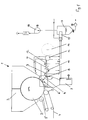
- FIG. 1 the diagram of a dust removal system a tissue machine
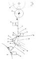
- Fig. 2 shows a detailed representation of each System elements
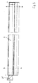
- Fig. 3 is a view of an upper disconnection box
- FIG. 5 a view of a lower one Partition box
- Fig. 6a and 6b show sections through Fig. 5.
- Fig. 1 shows the scheme of dust removal from a paper web.
- the paper dryer 1 is located a drying cylinder 2 and a drying hood 3, from which hot air the paper web 4 guided around the drying cylinder 2 is blown.
- the At the entrance the paper web is still guided over pressure rollers 5, 5 '.
- To the paper web 4 is dried by means of a scraper 6 scraped off the drying cylinder 2.
- this creates a large one Amount of dust on the other hand, fibers are easily removed from the Paper surface lifted off.
- this stabilizer 8 can be lowered fold, so that afterwards the paper web is listed again without problems can be.
- an air separation box 9 which further stabilization of the web and separates air from the top of the paper web. That there is then another disconnection box 10 on the underside the paper web into the dust-laden and carried on the bottom Air is deflected. Simply by the dynamic pressure of the air carried this has already been removed and hardly any extraction is required.
- Subsequent to the lower disconnection box 10 is usually located a traversing measuring device 11 for recording the paper web properties.
- Another separation box is for further dust separation 12 provided on the top of the paper web before the paper web is wound onto the drum 14 via a work roll 13. All with Dust-laden air streams are passed through a separator 15, in where the dust is separated by injecting water. The air is then sucked off by a fan 16, which with dust loaded water gets into a container 17 and from there as waste water is dissipated.
- Fig. 2 shows the part of the dust extraction in detail. It's the one here To detect drying cylinder 2, of which the paper web 4 by means of Scraper 6 is scraped off. Part of the dust-blown air is thereby through the pivotable stabilizer 8 down into the Committee 7 distracted. Then the paper becomes Disconnection box 9, which for stable paper web guidance has curved guide surface 18. The paper web runs here Inlet 18 'tangentially on this disconnection box 9 and leaves the Partition box at the outlet 18 "also tangential. Through this curved Guide surface 18 generates the required web tension, so that stable web guidance is always guaranteed. At the inlet 18 ' Air carried by the paper web is diverted and into a suction slot 19 out.
- the wall 20 of the suction slot 19 is articulated, whereby the suction slot 19 is adjustable. To clean the Disconnect box, this wall 20 can be folded all the way up and thus the suction channel 21 are released for cleaning.
- the inner surfaces of the disconnect box are smooth and have no edges, corners or other places where dust can accumulate. That too cleaning of the junction box is made easier.
- the paper web comes under a small angle, preferably from 1 ° to 5 °, for example here from 1 ° to 2 °, which in turn ensures good web guidance.
- the entrained air is here in the box 10 via a suction slot 22 guided.
- This suction slot 22 has a baffle 23, which for optimal air separation is adjustable.
- At the outlet of the Paper web from the disconnect box 10 can be supplied to air Vortex formation and the associated new generation of dust Avoid occurrence of negative pressure.
- the web After passing the paper web by a traversing measuring device 11, the web is over another Disconnect box 12, which is analogous to the lower disconnect box 10 is executed. Subsequently, the paper web 4 on rollers 13 on the Reel 14 rolled up.
- Fig. 3 shows a view of an upper disconnect box 9, the left here Drive side (marked with TS) and on the right the so-called driver side (marked with FS) of the paper machine is marked.
- the air gets over a suction pipe 25 is discharged from the disconnection box 9 on the drive side.
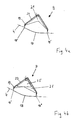
- FIGS. 4a and 4b show a cross section of the disconnection box 9 in the vicinity according to the driver's side according to line A-A or near the drive side according to Line B-B. It can be seen here that the cross section of the suction channel 21 of the driver side increases towards the drive side. This ensures that the Speeds are almost constant in all points across the web width are. So there are no local differences in air extraction and the risk of web breaks is reduced. In Figures 4a and 4b the leadership of the paper web 4 is clearly visible, which over the Guide surface 18 of the disconnection box 9 is guided.
- the paper web 4 runs in and out tangentially and it is through the design of the inlet 18 'or the outlet 18 "is ensured, that there is no further dust generation by the deflection.
- the air from the boundary layer is through the suction slot 19 in the Collection channel 21 passed.
- the chamber wall 20 is designed to be pivotable, so that on the one hand the suction slot 19 can be adjusted and the furthermore the disconnection box 9 can be opened for cleaning.
- FIG. 5 now shows the view of a lower disconnection box 10, again the drive side on the left and the driver side of the paper machine on the right, whereby the suction takes place via a line 26, 27 on the drive side.
- FIG. 6a shows the cross section of the disconnect box 10 on the driver's side according to line C-C.
- the disconnect box 10 clearly visible.
- the air is through the baffle 23 passed into the disconnection box 10. More air can flow out the paper web 4 is sucked off from the separation box 10 through an opening 28 become.
- the cross section of the disconnect box 10 is on the Drive side shown according to line D-D.
- Suction cross sections 26 and 27 can be seen.
Landscapes
- Paper (AREA)
- Control And Other Processes For Unpacking Of Materials (AREA)
- Registering, Tensioning, Guiding Webs, And Rollers Therefor (AREA)
- Advancing Webs (AREA)
Applications Claiming Priority (2)
| Application Number | Priority Date | Filing Date | Title |
|---|---|---|---|
| AT195099 | 1999-11-18 | ||
| AT0195099A AT408462B (de) | 1999-11-18 | 1999-11-18 | Verfahren und vorrichtung zur staubabtrennung von einer laufenden papierbahn |
Publications (2)
| Publication Number | Publication Date |
|---|---|
| EP1101863A2 true EP1101863A2 (fr) | 2001-05-23 |
| EP1101863A3 EP1101863A3 (fr) | 2003-07-02 |
Family
ID=3524556
Family Applications (1)
| Application Number | Title | Priority Date | Filing Date |
|---|---|---|---|
| EP00124067A Pending EP1101863A3 (fr) | 1999-11-18 | 2000-11-06 | Procédé et dispositif pour enlever de la poussière d'une bande de papier en défilement |
Country Status (5)
| Country | Link |
|---|---|
| US (1) | US6457204B1 (fr) |
| EP (1) | EP1101863A3 (fr) |
| AT (1) | AT408462B (fr) |
| BR (1) | BR0005439A (fr) |
| CA (1) | CA2325507A1 (fr) |
Cited By (4)
| Publication number | Priority date | Publication date | Assignee | Title |
|---|---|---|---|---|
| EP1731670A1 (fr) * | 2005-06-10 | 2006-12-13 | Milltech S.r.l. | Appareil de nettoyage, en particulier pour des machines à papier |
| EP1746207A3 (fr) * | 2005-07-22 | 2007-07-04 | Milltech S.r.l. | Dispositif pour stabiliser une bande de papier durant sa fabrication |
| CN106780983A (zh) * | 2017-01-20 | 2017-05-31 | 华南师范大学 | 一种带除尘装置的纸币处理装置 |
| CN117228405A (zh) * | 2023-09-08 | 2023-12-15 | 广东东一钢结构有限公司 | 一种用于合金钢构件的简易分条机张力控制装置 |
Families Citing this family (8)
| Publication number | Priority date | Publication date | Assignee | Title |
|---|---|---|---|---|
| DE102010056576B8 (de) * | 2010-12-30 | 2015-05-07 | Paprima Industries Inc. | Papierherstellungsmaschine und Verfahren zum Herstellen von Papier |
| US9108229B2 (en) | 2011-06-17 | 2015-08-18 | The Procter & Gamble Company | Method and apparatus for particulate removal from moving paper webs |
| US8657998B2 (en) | 2011-06-17 | 2014-02-25 | The Procter & Gamble Company | Method and apparatus for particulate removal from moving paper webs |
| CN110479697B (zh) * | 2019-08-19 | 2021-10-19 | 河南宝合元汽车配件有限公司 | 一种废料清理设备 |
| CN112779811B (zh) * | 2021-01-29 | 2022-10-04 | 恒安(重庆)生活用纸有限公司 | 纸机操作室正风压装置 |
| CN113787027B (zh) * | 2021-09-16 | 2023-07-11 | 湖南财政经济学院 | 一种用于计算器内部吸尘清洁装置 |
| CN114405896B (zh) * | 2022-01-20 | 2022-11-15 | 江苏凯华铝业有限公司 | 一种压花铝板表面花纹压延加工方法 |
| CN117206313B (zh) * | 2023-11-08 | 2024-01-02 | 中建三局集团(深圳)有限公司 | 一种建筑废弃木材智能回收处理设备 |
Family Cites Families (10)
| Publication number | Priority date | Publication date | Assignee | Title |
|---|---|---|---|---|
| SE459105B (sv) * | 1987-10-01 | 1989-06-05 | Valmet Paper Machinery Inc | Saett och anordning foer bortfoerande av damm som frigoers vid losskraeppning av en pappersbana |
| US5291628A (en) * | 1991-12-12 | 1994-03-08 | Xerox Corporation | High velocity air cleaner |
| JP2820599B2 (ja) * | 1993-08-31 | 1998-11-05 | 株式会社伸興 | 除塵装置 |
| US5466298A (en) * | 1993-10-01 | 1995-11-14 | James River Paper Company, Inc. | Web cleaning method |
| US5490300A (en) * | 1994-04-25 | 1996-02-13 | Horn; Paul E. | Air amplifier web cleaning system |
| US5836044A (en) * | 1995-05-26 | 1998-11-17 | Chapman Corporation | Surface cleaner and collector system |
| US5878462A (en) * | 1996-05-21 | 1999-03-09 | Valmet-Karlstad Ab | Dust removal apparatus |
| US6148831A (en) * | 1996-10-25 | 2000-11-21 | Valmet Corporation | Method for cleaning a web |
| FI104099B (fi) * | 1996-10-25 | 1999-11-15 | Valmet Corp | Menetelmä ja laite paperikoneella tai vastaavalla tai sen jälkikäsittelylaitteella pölyn poistamiseksi |
| DE19726897C2 (de) * | 1997-06-25 | 2000-01-13 | Voith Sulzer Papiermasch Gmbh | Verfahren zum Reinigen eines Transportbandes |
-
1999
- 1999-11-18 AT AT0195099A patent/AT408462B/de not_active IP Right Cessation
-
2000
- 2000-11-06 EP EP00124067A patent/EP1101863A3/fr active Pending
- 2000-11-08 CA CA002325507A patent/CA2325507A1/fr not_active Abandoned
- 2000-11-14 US US09/712,755 patent/US6457204B1/en not_active Expired - Fee Related
- 2000-11-17 BR BR0005439-9A patent/BR0005439A/pt active Search and Examination
Cited By (4)
| Publication number | Priority date | Publication date | Assignee | Title |
|---|---|---|---|---|
| EP1731670A1 (fr) * | 2005-06-10 | 2006-12-13 | Milltech S.r.l. | Appareil de nettoyage, en particulier pour des machines à papier |
| EP1746207A3 (fr) * | 2005-07-22 | 2007-07-04 | Milltech S.r.l. | Dispositif pour stabiliser une bande de papier durant sa fabrication |
| CN106780983A (zh) * | 2017-01-20 | 2017-05-31 | 华南师范大学 | 一种带除尘装置的纸币处理装置 |
| CN117228405A (zh) * | 2023-09-08 | 2023-12-15 | 广东东一钢结构有限公司 | 一种用于合金钢构件的简易分条机张力控制装置 |
Also Published As
| Publication number | Publication date |
|---|---|
| ATA195099A (de) | 2001-04-15 |
| US6457204B1 (en) | 2002-10-01 |
| EP1101863A3 (fr) | 2003-07-02 |
| CA2325507A1 (fr) | 2001-05-18 |
| AT408462B (de) | 2001-12-27 |
| BR0005439A (pt) | 2001-07-31 |
Similar Documents
| Publication | Publication Date | Title |
|---|---|---|
| DE69620479T2 (de) | Verfahren und vorrichtung zum entfernen von staub für eine papierherstellungs- oder papierveredelungsmaschine oder dergeleichen | |
| AT508470B1 (de) | Verfahren und vorrichtung zum übertragen einer faserbahn von einem stützgewebe zu einem anderen | |
| DE4112355A1 (de) | Pressenpartie einer papiermaschine | |
| AT408462B (de) | Verfahren und vorrichtung zur staubabtrennung von einer laufenden papierbahn | |
| DE3884628T2 (de) | Vorrichtung zum halten der kanten einer bahn an einem trocknerfilz. | |
| DE3344217C2 (fr) | ||
| DE69806039T2 (de) | Einrichtung zur entstaubung an einer maschine zur produktion von krepp-papier | |
| EP0824158B1 (fr) | Dispositif pour le séchage d'une bande fibreuse | |
| EP3987113B1 (fr) | Machine destinée à la fabrication d'une bande de matière fibreuse | |
| EP1072722B1 (fr) | Section de séchage | |
| DE4121432A1 (de) | Geraet zum messen des zustands eines filzes und zum instandsetzen des filzes | |
| EP1285991A2 (fr) | Dispositif pour le traitement d'une bande fibreuse | |
| EP1338685A1 (fr) | Méthode et dispositif de nettoyage de la zone de détachage dans une carde | |
| EP1354677A2 (fr) | Dispositif de coupe à jet d'eau | |
| EP4038235B1 (fr) | Dispositif et procédé pour appliquer de l'air de traitement | |
| DE3800669C2 (fr) | ||
| DE3731541C2 (de) | Verfahren und Vorrichtung zur stabilisierten Führung einer bewegten Materialbahn | |
| DE19636791A1 (de) | Verfahren und Vorrichtung zur Entfernung von Papierbahnresten von einem Band | |
| DE102007024322A1 (de) | Verfahren und Anlage zum Überführen der Papier- oder Kartonbahn ins Ausschusssystem bei Konzepten mit geschlossener Bahnführung | |
| DE102014225262A1 (de) | Randstreifen-Schneideeinrichtung | |
| DE4335024C2 (de) | Pressenpartie einer Papiermaschine und Überführeinrichtung | |
| EP0689627A1 (fr) | Transport sans traction d'une bande dans une section de compression | |
| AT520935B1 (de) | Vorrichtung und Verfahren zum Überführen eines Streifens | |
| DE19922428B4 (de) | Siebtrommelvorrichtung | |
| DE102007043087A1 (de) | Verfahren und Vorrichtung zum Überführen der Papierbahn von einem Stützgewebe |
Legal Events
| Date | Code | Title | Description |
|---|---|---|---|
| PUAI | Public reference made under article 153(3) epc to a published international application that has entered the european phase |
Free format text: ORIGINAL CODE: 0009012 |
|
| AK | Designated contracting states |
Kind code of ref document: A2 Designated state(s): AT BE CH CY DE DK ES FI FR GB GR IE IT LI LU MC NL PT SE TR |
|
| AX | Request for extension of the european patent |
Free format text: AL;LT;LV;MK;RO;SI |
|
| PUAL | Search report despatched |
Free format text: ORIGINAL CODE: 0009013 |
|
| AK | Designated contracting states |
Designated state(s): AT BE CH CY DE DK ES FI FR GB GR IE IT LI LU MC NL PT SE TR |
|
| AX | Request for extension of the european patent |
Extension state: AL LT LV MK RO SI |
|
| 17P | Request for examination filed |
Effective date: 20031009 |
|
| AKX | Designation fees paid |
Designated state(s): AT BE CH CY DE DK ES FI FR GB GR IE IT LI LU MC NL PT SE TR |
|
| 18W | Application withdrawn |
Effective date: 20090603 |
|
| STAA | Information on the status of an ep patent application or granted ep patent |
Free format text: STATUS: THE APPLICATION IS DEEMED TO BE WITHDRAWN |
|
| 18D | Application deemed to be withdrawn |
Effective date: 20090603 |
|
| D18W | Application withdrawn (deleted) |