EP1101868A1 - Système collecteur de liquides répandus au voisinage de rails de chemin de fer - Google Patents
Système collecteur de liquides répandus au voisinage de rails de chemin de fer Download PDFInfo
- Publication number
- EP1101868A1 EP1101868A1 EP00204025A EP00204025A EP1101868A1 EP 1101868 A1 EP1101868 A1 EP 1101868A1 EP 00204025 A EP00204025 A EP 00204025A EP 00204025 A EP00204025 A EP 00204025A EP 1101868 A1 EP1101868 A1 EP 1101868A1
- Authority
- EP
- European Patent Office
- Prior art keywords
- pan
- center
- pans
- rails
- crossties
- Prior art date
- Legal status (The legal status is an assumption and is not a legal conclusion. Google has not performed a legal analysis and makes no representation as to the accuracy of the status listed.)
- Withdrawn
Links
- 239000007788 liquid Substances 0.000 title claims abstract description 31
- 238000000034 method Methods 0.000 title claims abstract description 16
- 238000007789 sealing Methods 0.000 claims abstract description 34
- 238000009434 installation Methods 0.000 claims abstract description 13
- 239000000463 material Substances 0.000 claims abstract description 10
- 229920003023 plastic Polymers 0.000 claims abstract description 6
- 239000004033 plastic Substances 0.000 claims abstract description 6
- 239000012530 fluid Substances 0.000 claims description 16
- 239000012858 resilient material Substances 0.000 claims description 8
- 239000002991 molded plastic Substances 0.000 claims description 6
- 239000007787 solid Substances 0.000 claims description 5
- 239000004698 Polyethylene Substances 0.000 claims description 2
- -1 polyethylene Polymers 0.000 claims description 2
- 229920000573 polyethylene Polymers 0.000 claims description 2
- 239000011344 liquid material Substances 0.000 claims 1
- 230000003014 reinforcing effect Effects 0.000 claims 1
- 239000011343 solid material Substances 0.000 claims 1
- 229920001903 high density polyethylene Polymers 0.000 abstract description 6
- 239000004700 high-density polyethylene Substances 0.000 abstract description 6
- 230000003137 locomotive effect Effects 0.000 description 5
- 230000008602 contraction Effects 0.000 description 4
- 239000004576 sand Substances 0.000 description 4
- 230000004048 modification Effects 0.000 description 3
- 238000012986 modification Methods 0.000 description 3
- 230000006978 adaptation Effects 0.000 description 2
- 238000005452 bending Methods 0.000 description 2
- 238000010276 construction Methods 0.000 description 2
- 230000013011 mating Effects 0.000 description 2
- 239000002245 particle Substances 0.000 description 2
- XLYOFNOQVPJJNP-UHFFFAOYSA-N water Substances O XLYOFNOQVPJJNP-UHFFFAOYSA-N 0.000 description 2
- 230000007423 decrease Effects 0.000 description 1
- 239000011152 fibreglass Substances 0.000 description 1
- 238000003780 insertion Methods 0.000 description 1
- 230000037431 insertion Effects 0.000 description 1
- 239000003562 lightweight material Substances 0.000 description 1
- 239000002184 metal Substances 0.000 description 1
- 238000005086 pumping Methods 0.000 description 1
- 230000002787 reinforcement Effects 0.000 description 1
- 230000000284 resting effect Effects 0.000 description 1
- 239000011435 rock Substances 0.000 description 1
Images


Classifications
-
- E—FIXED CONSTRUCTIONS
- E01—CONSTRUCTION OF ROADS, RAILWAYS, OR BRIDGES
- E01B—PERMANENT WAY; PERMANENT-WAY TOOLS; MACHINES FOR MAKING RAILWAYS OF ALL KINDS
- E01B19/00—Protection of permanent way against development of dust or against the effect of wind, sun, frost, or corrosion; Means to reduce development of noise
- E01B19/006—Means for protecting the underground against spillage
-
- E—FIXED CONSTRUCTIONS
- E01—CONSTRUCTION OF ROADS, RAILWAYS, OR BRIDGES
- E01B—PERMANENT WAY; PERMANENT-WAY TOOLS; MACHINES FOR MAKING RAILWAYS OF ALL KINDS
- E01B1/00—Ballastway; Other means for supporting the sleepers or the track; Drainage of the ballastway
- E01B1/008—Drainage of track
Definitions
- This invention relates to a system for collecting liquid spillage inadvertently spilled along a railroad track primarily from the filling or emptying of railway tank cars or the fueling of locomotives.
- the system includes a plurality of center pans and side pans supported on the crossties of the railway track for the draining of any liquid spillage from the pans into an enclosed transverse drain conduit positioned between a pair of crossties beneath the rails for flow into a collection container.
- a pan collection structure for a railway track has been provided utilizing center pans between the rails and side pans outside the rails.
- the pans heretofore have been supported on crossties and drain into a transverse drain conduit positioned between a pair of crossties beneath the pans.
- U.S. patent no. 4,300,721 dated November 17, 1981 shows a system for collecting liquid spillage having a plurality of center pans and side pans.
- Vertical drain conduits extend from the pans into an enclosed transverse drain conduit for drainage.
- the transverse drain conduit empties into a collection receptacle.
- the pans are formed of a molded plastic material, separate vertical drains are connected to the bottom of the pans. Further, while side edges of the pans are positioned adjacent the vertical web of the rails, a separate caulking material is used to provide sealing against the rails.
- the rigid vertical drain conduits are threaded into openings in the pans and in the enclosed transverse drain conduit.
- U.S. Patent No. 5,435,458 dated July 25, 1995 shows a spill containment device for railroads in which slidable covers are positioned over center pans for closing the center pans when not required to be open to contain a potential spill. Foldable hinged panels are utilized for closing the outer field pans.
- a closed system for the collection of liquid spillage on a railroad track may be provided that may be installed in a minimum of time with sealing against the rails.
- the present invention is directed to a system for collecting spillage on a railway track including the apparatus or structure positioned on the crossties beneath railway cars and the method for installing such a collection structure between the rails and outwardly of the rails.
- the collection structure includes a plurality of center and side pans molded to shape from a resilient plastic material, such as high density polyethylene.
- the resilient center pans between rails have a pair of upwardly extending inclined side flanges which fit beneath the heads of the rails in sealing relation with the rails without any additional sealing members.
- a downwardly extending tubular drain pipe is molded onto each pan and fits within an enclosed transverse drain conduit positioned between a pair of crossties beneath the rails.
- the transverse drain conduit has an upper opening receiving each vertical drain pipe and a resilient annular seal about the upper opening receives the vertical drain pipe to provide a resilient sealing relation and to position the pans accurately.
- the outer ends of the pans in one transverse row have outwardly extending end flanges which lap end flanges on an adjacent transverse row of pans arranged in end to end relation.
- Fasteners connect the lapping end flanges of adjacent transverse rows together to permit limited relative longitudinal movement which may result from temperature expansion or contraction, for example.
- a preferred assembly method includes the insertion of center pans between the rails with one resilient side flange positioned beneath the rail against the vertical web of the rail under the head of the rail with the pan being inclined upwardly from the rail.
- the inclined pan is then pivoted downwardly with the bottom of the center pan resting against the crossties and the opposite resilient side flange in contact relation with the upper surface of the rail.
- the opposite resilient side flange is forced by a suitable tool downwardly beneath the head of the rail where it snaps outwardly against the vertical web of the rail in sealing relation thereto.
- a downwardly extending integral drain pipe molded on each of the pans is vertically aligned with the lower receiving opening in the transverse drain conduit for initial positioning of the center pan accurately with the transverse drain conduit.
- An annular resilient seal is positioned within the opening of the drain conduit to receive the vertical drain pipe in sealing relation.
- each of the resilient side flanges may be forced or pushed beneath the head of the adjacent rail for snapping beneath the head of the adjacent rail in sealing relation with the vertical web of the rail.
- Each of the side pans has a resilient side flange in sealing relation with the vertical web of the adjacent rail. Fasteners are provided to secure the side pans to the crossties and to permit limited expansion and contraction thereof. Ballast on an outwardly extending lower flange or foot of the side flange assists in maintaining the side pan in sealing relation against the rail.
- One embodiment of the invention provides removable covers for closing the center and field pans when the pans are not required to be open to contain a potential spill.
- the center cover has opposed side flanges which provide longitudinal flow channels and also fit beneath the heads of the adjacent rails.
- Another embodiment of the invention provides removable covers for pans including side flanges which provide longitudinal flow channels and have spouts for the drainage of fluids from the flow channels. Slidable covers without spouts are also provided for opening of the pans.
- the present invention is directed to a pan system for collecting liquid spillage on a railroad track.
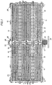
- two adjacent transverse rows of drain pans are shown including a pair of center pans generally indicated at 10 arranged in an end to end relation between rails 12 of the railroad track and a pair of side pans generally indicated at 14 arranged in end to end relation along the outer side of each rail 12.
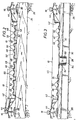
- Each rail 12 as shown particularly in Figures 2 and 3 includes an upper head or ball 16, a vertical web 18, and a lower base 20.
- Lower base 20 is mounted on tie plates 22 supported on crossties 24.
- Crossties 24 are mounted on ballast 26 normally comprising crushed rock.
- Pans 10 and 14 are formed of a molded lightweight plastic material, preferably high density polyethylene, having a thickness of preferably about 1 ⁇ 4 inch to provide flexibility and resilience. Pans 10 and 14 formed of a lightweight material may be easily stacked vertically for storage or transport prior to installation on a railroad track such as shown in Figure 5 for center pans 10. Also, relatively long length pans such as fifteen (15) feet in length, function in a satisfactory manner. Thus, each row shown in Figure 1 may have a length of fifteen (15) feet.
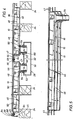
- transverse drain conduit 28 For the collection of liquid spillage from pans 10 and 14, an enclosed transverse drain conduit generally indicated at 28 in Figures 3,4, and 7 is positioned between a pair of crossties 24 beneath the drainage end of pans 10 and 14 to receive the liquid spillage from pans 10 and 14.
- Conduit 28 is of a rectangular cross section having a sloping lower wall 30 and an upper wall 32. Upper wall 32 has an opening 34 for each of pans 10 and 14 to receive the liquid spillage from pans 10 and 14.
- the extending lower sloping end of transverse drain conduit 28 is connected to a catch basin 35 having a longitudinal drain pipe 36 which extends to a collection facility or container (not shown). If desired, catch basin 35 may be omitted with drain pipe 36 connected directly to an end of drain conduit 28.
- Each center pan 10 of a molded plastic construction is resilient and includes a bottom 40, a pair of opposed sides 42, and a flexible resilient upper side flange or lip 44 extending laterally outwardly from each side 42.
- Pan bottom 40 is supported on the upper surface of crossties 24 and has a plurality of molded ribs to provide flow channels for pan 10 and to reinforce pan 10.
- raised rib sections 46 at the upper end 45 of center pan 10 as shown in Figure 2 slope downwardly to the lower opposed end 47 of pan 10 for the drainage of liquid from upper end 45 to lower end 47.
- Main flow channels 48 along bottom 40 are provided adjacent raised rib sections 46. Rib sections 46 have ribs or corrugations 50 defining shallow flow channels 52 therebetween.
- Rib sections 46 for pan 10 having a length of fifteen (15) feet have a slope of between about one (1) and (2) inches from upper end 45 to lower end 47.
- Flow channels 48 as shown in Figure 2 adjacent upper end 45 are deep and are shallow adjacent lower end 47 as shown in Figure 3. Thus, the depth of flow channels 48 progressively decreases from end 45 to end 47.
- Flow channels 52 remain at a constant depth between ends 45 and 47.
- Flow channels 48 and 52 are effective in the drainage of solid particles, such as sand, from pan 10.
- Each molded center pan 10 has an integral downwardly extending drain pipe 54 defining an inset annular shoulder 56 to receive in supporting relation a metal grate 58. Drain pipe 54 tapers in a downward direction and is flexible to facilitate fitting within a vertically aligned opening 34 in transverse drain conduit 28.
- an elastomeric sealing sleeve 60 is mounted within opening 34 to receive in sealing relation the lower end of vertical drain pipe 54.
- Sleeve 60 has an annular shoulder 62 that fits about opening 34 and contacts in sealing relation the upper surface of to upper wall 32 of transverse drain conduit 28. The resilience of sleeve 60 and tapered drain pipe 54 provide an effective sealing relation.
- each end 45, 47 has an extending upper end flange 64 which laps an adjacent flange 64 of an adjacent center pan 10.
- Aligned elongate slots 66 are provided in lapping flanges 64 and fasteners 68 having resilient washers fit within aligned slots 66 and are tightened to hold flanges 64 together at ends 45 and 47. Slots 66 permit limited temperature expansion and contraction of adjacent center pans 10 of about one (1) inch.
- Center pans 10 may be easily installed between rails 12 in a minimum of time.
- Transverse drain conduit 28 with sleeves 60 within openings 34 is positioned between a pair of crossties 24 with one crosstie 24 removed to provide adequate space for transverse drain conduit 28.
- a preferred installation method as shown partially in Figure 2 in broken lines comprises the positioning of one resilient side flange 44 beneath the head 16 of an adjacent rail 12 with pan 10 inclined upwardly at about a thirty (30) degree angle to the adjacent rail 12.
- Vertical drain pipe 54 is initially aligned vertically with an associated opening 34 and sealing sleeve 60. Then, the center pan 10 is pushed downwardly with the bottom 40 of pan 10 supported on the upper surface of the crossties 24 and pipe 54 received within resilient sleeve 60 in sealing relation.
- Another method of installing center pan 10 comprises the aligning of drain pipe 54 with sleeve 60 and the pushing or forcing of center pan 10 downwardly onto crossties 24 between rails 12 without inclining center pan 10 so that both side flanges 44 contact the upper surface of adjacent heads 16 and are held thereon. Both resilient side flanges 44 may then be forced beneath heads 16 by a workman with a suitable tool for snapping of side flanges 44 into sealing position beneath heads 16.
- Each side pan 14 has a bottom 72 and raised rib sections 74.
- Main flow channels 76 are provided between raised rib sections 74 which slope downwardly from an upper end 77 shown in Figure 6 to a lower end shown in Figure 7.
- An integral drain tube or pipe 78 extends downwardly from bottom 72 for fitting within an elastomeric sealing sleeve 60 in a manner similar to outer pan 10. Grate 79 is supported on drain pipe 78.
- An inner side 80 has an extending side flange 82 which fits beneath head 16 in sealing relation generally at the juncture of head 16 and vertical web 18. Drain tube or pipe 78 is positioned for urging side flange 82 into sealing relation with head 16 at the lower end of side pan 14 when drain pipe 78 is received within sealing sleeve 60. Also, bottom 72 has elongate slots 81 receiving lag screws 83 and washers which are secured to the crossties 24. An outer channel-shaped side 86 of side pan 14 has an extending lower flange 88 covered with ballast to assist in maintaining side pan 14 in sealing position against head 16 of the adjacent rail 12.
- Each side pan 14 has an upper end flange at each end thereof which is adapted to be positioned and secured in lapping relation to a mating end flange on an adjacent side pan 14 in a manner similar to lapping flanges 64 secured by fasteners 68 as shown in Figure 4 for center pan 10.
- Side pans 14 are arranged in transversely aligned position with center panel 10.
- resilient side flange 82 is pushed manually tightly against the junction of head 16 and vertical web 18 of adjacent rail 12 with drain pipe 78 aligned vertically with seal 60. Then, downwardly extending drain pipe 78 is lowered within elastomeric sealing sleeve 60 in transverse drain conduit 28.
- Ballast is then positioned over extending flange 88 and lag screws 83 with washers are inserted in the crossties through suitable elongate slots 81 in bottom 72 of side pan 14.
- the lag screws 83 are received within a relatively small elongated slot so that limited expansion and contraction of side panel 14 less than about one (1 ) inch is provided. In some instances, lag screws 83 may be omitted.
- Spikes 85 are provided for flange 88 and are of a length of about eight (8) inches for extending within ballast 26 for securement of side pans 14.
- the arrangement of the rib sections in center panel 10 and side panel 14 provides longitudinal flow channels for the fluid and also solid particles carried by the fluid. Sand is oftentimes deposited into pans 10 and 14 and the arrangement of the longitudinally extending flow channels permits the sand to drain easily into the end drain tube. Heretofore, particularly for flat pans, sand has tended to deposit in various locations of the flat pans.
- the molded plastic pans 10 and 14 formed preferably of polyethylene provides a substantial resilience and flexibility. Vertical drain pipes which are molded with the pans fit within resilient sleeves in the transverse drain conduit and this permits the track to move relative to the transverse conduit.
- the limited flexure or movement of the drain pans relative to the transverse drain conduit is important since the operation of a train on the rails causes a vertical pumping action which may be transmitted to the drain pans and cause some movement of the drain pans.
- movement of the drain pans and the track is not transmitted to the enclosed lower transverse drain conduit and a substantially liquid tight seal is maintained between the pans and the rails as well as the transverse drain conduit.
- the drain conduit has been illustrated in the drawings as positioned at an end of the drain pans, it is apparent that the downward extending drain tube or pipe may be positioned at other locations such as the center of the drain pan, for example.
- the drain pans may be of a relatively long length, such as fifteen (15) feet in length and yet be lightweight. This would permit the easy stacking of vertical pans and side pans for shipment or for storage.
- Other moldable materials may be suitable for the drain pans such as fiberglass.
- Center pan 10 is identical to center pan 10 in the embodiment of Figures 1-7 to include a bottom 40, a pair of opposed sides 42 and a flexible resilient upper side flange or lip 44 extending laterally outwardly from each side 42.
- one side flange 44 is preferably positioned beneath head 16 of one rail 12 and the other opposed side flange 44 is forced downwardly past head 16 of the other rail 12 snapping beneath head 16 against vertical web 18.
- Center cover or lid 90 has an upper arcuate body 92 and a trough generally indicated at 94 along each side thereof defining a fluid flow passage.
- Trough 94 is defined by a downwardly extending generally vertical side 96, a bottom 98, and an upwardly extending outer flange 100 inclined outwardly for fitting beneath head 16 of rail 12.
- Bottom 98 contacts and is supported on side flange 44 of center pan 10.
- a drain spout 102 extends downwardly from bottom 98 and is mounted at a location about 1/2 the length of trough 94.
- Trough 94 slopes downwardly from each end of cover 90 to spout 102.
- Side flange 44 of the subjacent center pan 10 has an opening 101 to receive spout 102.
- Adjacent lids or covers 10 are arranged in end to end relation and may have mating lapping end flanges for minimizing liquid drainage thereat into the lower closed center pan 10.
- covers 90 are formed of a resilient material, such as high density polyethylene, lids 90 may be removed from center pan 10 by forcing flange 100 on one trough 34 inwardly for clearing head 16 of rail 12 thereby permitting the removal of covers 92 so that access to center pan 10 is provided as is desired for loading and unloading railway tank cars and fueling locomotives on rails 12 over center pans 10. Rain water easily flows along troughs 90 for discharge from spouts 102 into the ballast adjacent the ends of troughs 90.
- Side pans 14 are shown in Figures 8 and 9 and side covers 104 are shown for side pans 14.
- Side pans 14 have channel-shaped sides 86 and side flanges 82.
- Covers 104 have a trough 106 on one side adjacent rail 12 with a spout 108 extending downwardly therefrom.
- the other side 110 is supported on channel 86.
- a lip 112 fits against the side of channel-shaped side 86 to urge inner side flanges of covers 104 into engagement with adjacent rail 12.
- Drain pipes 78 on outer pans 14 and drain pipe 54 on center pan 10 extend within transverse drain conduit 28.
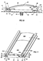
- a modified lid or cover 90A is shown in Figure 11 for fitting over a subjacent center pan 10.
- Cover 90A has an upper arcuate body 92A and a trough generally indicated at 94A along each side thereof to form a fluid flow passage.
- Trough 94A has an inner side 96A, a bottom 98A, and an upwardly extending outer flange 100A inclined outwardly for fitting beneath head 16 of rail 12.
- covers 90A may be removed from center pan 10 by sliding along flanges 44 of center pan 10. Covers 90A may be positioned on the crossties after removal from pans 10 to permit drainage from railway cars or locomotives directly into center pans 10. If desired, lids 90A may be removed by forcing lips 100A from beneath head 10 of rail 12 since cover 90A is formed of a resilient material such as high density polyethylene. Sides 94A are provided with a desired slope for adequate drainage of fluids along troughs 94A. Handles may be provided on covers 90A, if desired, to assist in installation and removal of covers 90A.
Landscapes
- Engineering & Computer Science (AREA)
- Architecture (AREA)
- Civil Engineering (AREA)
- Structural Engineering (AREA)
- Railway Tracks (AREA)
- Sewage (AREA)
- Sink And Installation For Waste Water (AREA)
- Details Of Rigid Or Semi-Rigid Containers (AREA)
Applications Claiming Priority (2)
| Application Number | Priority Date | Filing Date | Title |
|---|---|---|---|
| US09/440,912 US6290143B1 (en) | 1996-05-02 | 1999-11-16 | Apparatus and method for collecting liquid spillage at rail facilities |
| US440912 | 1999-11-16 |
Publications (1)
| Publication Number | Publication Date |
|---|---|
| EP1101868A1 true EP1101868A1 (fr) | 2001-05-23 |
Family
ID=23750701
Family Applications (1)
| Application Number | Title | Priority Date | Filing Date |
|---|---|---|---|
| EP00204025A Withdrawn EP1101868A1 (fr) | 1999-11-16 | 2000-11-16 | Système collecteur de liquides répandus au voisinage de rails de chemin de fer |
Country Status (3)
| Country | Link |
|---|---|
| US (2) | US6290143B1 (fr) |
| EP (1) | EP1101868A1 (fr) |
| CA (1) | CA2326021C (fr) |
Cited By (2)
| Publication number | Priority date | Publication date | Assignee | Title |
|---|---|---|---|---|
| KR100970752B1 (ko) | 2008-07-11 | 2010-07-16 | 한국철도공사 | 선로용 토양 오염방지판 및 이의 설치방법 |
| EP2100999A3 (fr) * | 2008-03-10 | 2012-10-31 | Eryk Ksiazkiewicz | Bassin pour la protection d'un chemin de fer contre la contamination du sol |
Families Citing this family (25)
| Publication number | Priority date | Publication date | Assignee | Title |
|---|---|---|---|---|
| US20060048469A1 (en) * | 2002-10-29 | 2006-03-09 | Maclean James G | Self-cleaning flooring system |
| US6941703B2 (en) * | 2002-10-29 | 2005-09-13 | Sani-Floor, Incorporated | Self-cleaning flooring system |
| US20090241442A1 (en) * | 2002-10-29 | 2009-10-01 | Maclean James G | Self-cleaning flooring system |
| DE20219018U1 (de) * | 2002-12-06 | 2003-04-10 | KLEIN Anlagenbau AG, 57572 Niederfischbach | Anlage zur Behandlung von Schüttgut |
| US7384496B2 (en) * | 2004-02-23 | 2008-06-10 | Checkpoint Systems, Inc. | Security tag system for fabricating a tag including an integrated surface processing system |
| CA2483315A1 (fr) * | 2004-09-27 | 2006-03-27 | Shea Taylor | Plateau d'egouttage a couvercle |
| DE102005013736A1 (de) * | 2005-03-22 | 2006-09-28 | Max Bögl Bauunternehmung Gmbh & Co.Kg | Gleisanlage und Betonplatte einer Festen Fahrbahn |
| US7374062B2 (en) * | 2005-04-01 | 2008-05-20 | Van Romer Edward W | Modular spill containment system |
| US7504024B1 (en) * | 2005-04-19 | 2009-03-17 | Thermaco, Inc. | Apparatus for draining at least one sink |
| DE102005054820A1 (de) * | 2005-11-15 | 2007-05-24 | Rail.One Gmbh | Feste Fahrbahn für Schienenfahrzeuge |
| US20080142525A1 (en) * | 2006-12-18 | 2008-06-19 | Brouillette Timothy Donald | Secondary drain pan |
| US8499962B1 (en) | 2008-04-10 | 2013-08-06 | Southwire Company | Rail car unloading catch pan system |
| US20110186583A1 (en) * | 2009-12-30 | 2011-08-04 | Transport Environmental Systems, Inc. | Support Matrix for Spill Containment Pan |
| SE535633C2 (sv) * | 2010-07-06 | 2012-10-23 | Joakim Flygare | Blockeringsresistenta slipers för tågväxlar, anordning vid växel samt metod för att åstadkomma en anordning vid växel |
| US9458616B2 (en) * | 2011-08-12 | 2016-10-04 | Mifab, Inc. | Floor sink frame and grate assembly |
| US20130306645A1 (en) * | 2012-05-15 | 2013-11-21 | Károly CSEK | Railroad spill containment tray |
| US9580240B2 (en) * | 2013-03-14 | 2017-02-28 | Performance Petroleum | Drip liner for hazardous materials |
| US20140283925A1 (en) * | 2013-03-21 | 2014-09-25 | Matthew L Justus | Fluids collection and drain system |
| USD754404S1 (en) * | 2013-11-05 | 2016-04-19 | Jansen Holding B.V. | Grating for the keeping of poultry |
| US20150361622A1 (en) * | 2014-06-13 | 2015-12-17 | Geoff Grantland | Flexible Accessible Railroad Pan System |
| US20160316712A1 (en) * | 2015-05-01 | 2016-11-03 | Kee3, Llc | Livestock production facility |
| CA2925260C (fr) | 2016-02-22 | 2023-09-19 | Robert A. Diplacido | Caniveau sureleve |
| USD787028S1 (en) | 2016-03-21 | 2017-05-16 | Zurn Industries, Llc | Elevator trench drain |
| US11795703B2 (en) | 2021-02-04 | 2023-10-24 | Zurn Industries, Llc | Elevator trench drain |
| US20250012480A1 (en) * | 2023-07-06 | 2025-01-09 | Midea Group Co., Ltd. | Condensation pans, heat pump systems, and methods of filtering condensate |
Citations (7)
| Publication number | Priority date | Publication date | Assignee | Title |
|---|---|---|---|---|
| US3773255A (en) * | 1972-01-13 | 1973-11-20 | Armco Steel Corp | Fluid collection assembly for railroad roadbed |
| US4300721A (en) | 1980-05-23 | 1981-11-17 | Oneida General Corporation | System for collecting liquid spillage at rail facilities |
| DE4008747A1 (de) * | 1990-03-19 | 1991-09-26 | Annette Becker | Gleistragwanne mit einer betonwanne mit einer abdichtungsschicht |
| US5435458A (en) | 1992-09-18 | 1995-07-25 | Safety-Kleen Corp. | Chemical spill containment apparatus |
| US5782405A (en) | 1993-12-27 | 1998-07-21 | Vincent; Jon R. | Railroad track collector pan system |
| EP0952253A1 (fr) * | 1998-04-14 | 1999-10-27 | Century Group Inc. | Système collecteur de liquides pour le voisinage de rails |
| US5974898A (en) | 1996-01-13 | 1999-11-02 | Robert Bosch Gmbh | Force sensor having test deflection device |
Family Cites Families (16)
| Publication number | Priority date | Publication date | Assignee | Title |
|---|---|---|---|---|
| US952253A (en) | 1909-05-18 | 1910-03-15 | Anthony Iske | Milk-protector. |
| US1408134A (en) | 1921-09-08 | 1922-02-28 | Walter T O'donnell | Track drain |
| DE539349C (de) | 1928-03-23 | 1931-11-30 | Herbert Ernest Dance | Messeinrichtung fuer Wechselstromanlagen, bei welcher zwei von der Spannung bzw. vomStrom beeinflusste, mit Wicklungen versehene und sich gegenseitig induzierende Messsysteme in Abhaengigkeit vom Produkt Volt mal Ampere eine Anzeige, Aufzeichnung, Integration oder Ausloesung von Schaltvorgaengen ausfuehren |
| US4010896A (en) | 1976-03-25 | 1977-03-08 | Stockton William N | Modular liquid collection system for railroad roadbeds |
| US4388357A (en) | 1979-01-23 | 1983-06-14 | True Temper Corporation | Sheet useful as a reservoir liner |
| US4406403A (en) | 1979-01-23 | 1983-09-27 | True Temper Corporation | Method of providing a containment reservoir |
| US4296884A (en) | 1979-01-23 | 1981-10-27 | True Temper Corporation | Containment reservoir and method |
| US4366846A (en) | 1979-06-29 | 1983-01-04 | True Temper Corporation | Method for collecting and storing liquid from along a railroad track section |
| US4299697A (en) | 1979-06-29 | 1981-11-10 | True Temper Corporation | Liquid containment and storage system for railroad track |
| US4311273A (en) | 1980-03-28 | 1982-01-19 | True Temper Corporation | Variable thickness fabric mat for railway track structure and method |
| US4651887A (en) * | 1986-01-08 | 1987-03-24 | Ashland Oil, Inc. | Spill catch pan |
| DE4125202C2 (de) | 1991-07-30 | 1994-02-10 | Werner Haag | System zum Auffangen von organischen Stoffen unterhalb von Schienenfahrzeugen |
| AT405952B (de) | 1991-10-21 | 2000-01-25 | Lindinger Klaus Johann | Vorrichtung zum schutz des schotterbettes von gleisanlagen gegen umweltschädliche tropfsubstanzen, insbesondere tropföl |
| US5975332A (en) * | 1996-10-09 | 1999-11-02 | Trans Environmental Systems, Inc. | Compact spill containment pan |
| US5775869A (en) * | 1996-10-15 | 1998-07-07 | Trans Environmental Systems, Inc. | Transportable spill containment pan |
| US6173856B1 (en) * | 2000-04-20 | 2001-01-16 | Ultratech International, Inc. | Spill containment pan |
-
1999
- 1999-11-16 US US09/440,912 patent/US6290143B1/en not_active Expired - Lifetime
-
2000
- 2000-11-16 EP EP00204025A patent/EP1101868A1/fr not_active Withdrawn
- 2000-11-16 CA CA002326021A patent/CA2326021C/fr not_active Expired - Lifetime
-
2001
- 2001-07-16 US US09/906,197 patent/US6415987B2/en not_active Expired - Lifetime
Patent Citations (7)
| Publication number | Priority date | Publication date | Assignee | Title |
|---|---|---|---|---|
| US3773255A (en) * | 1972-01-13 | 1973-11-20 | Armco Steel Corp | Fluid collection assembly for railroad roadbed |
| US4300721A (en) | 1980-05-23 | 1981-11-17 | Oneida General Corporation | System for collecting liquid spillage at rail facilities |
| DE4008747A1 (de) * | 1990-03-19 | 1991-09-26 | Annette Becker | Gleistragwanne mit einer betonwanne mit einer abdichtungsschicht |
| US5435458A (en) | 1992-09-18 | 1995-07-25 | Safety-Kleen Corp. | Chemical spill containment apparatus |
| US5782405A (en) | 1993-12-27 | 1998-07-21 | Vincent; Jon R. | Railroad track collector pan system |
| US5974898A (en) | 1996-01-13 | 1999-11-02 | Robert Bosch Gmbh | Force sensor having test deflection device |
| EP0952253A1 (fr) * | 1998-04-14 | 1999-10-27 | Century Group Inc. | Système collecteur de liquides pour le voisinage de rails |
Cited By (2)
| Publication number | Priority date | Publication date | Assignee | Title |
|---|---|---|---|---|
| EP2100999A3 (fr) * | 2008-03-10 | 2012-10-31 | Eryk Ksiazkiewicz | Bassin pour la protection d'un chemin de fer contre la contamination du sol |
| KR100970752B1 (ko) | 2008-07-11 | 2010-07-16 | 한국철도공사 | 선로용 토양 오염방지판 및 이의 설치방법 |
Also Published As
| Publication number | Publication date |
|---|---|
| US6415987B2 (en) | 2002-07-09 |
| US20010048033A1 (en) | 2001-12-06 |
| US6290143B1 (en) | 2001-09-18 |
| CA2326021A1 (fr) | 2001-05-16 |
| CA2326021C (fr) | 2004-02-03 |
Similar Documents
| Publication | Publication Date | Title |
|---|---|---|
| US6290143B1 (en) | Apparatus and method for collecting liquid spillage at rail facilities | |
| US4300721A (en) | System for collecting liquid spillage at rail facilities | |
| US6305569B1 (en) | Spill containment pan | |
| CA1329959C (fr) | Dispositif de percolation d'effluents d'egouts dans le sol | |
| US4366846A (en) | Method for collecting and storing liquid from along a railroad track section | |
| CA2217634C (fr) | Reservoir de confinement transportable | |
| US9267243B2 (en) | Surface and sub-surface drain system | |
| US6883336B2 (en) | Air conditioning condensation drainage system | |
| CA2268736C (fr) | Appareil et methode pour recueillir du liquide renverse des installations de rails | |
| DE3818952A1 (de) | Auffangvorrichtung in gleisanlagen, zum schutz von boden und grundwasser vor schadstoffeintrag | |
| US5782405A (en) | Railroad track collector pan system | |
| US4299697A (en) | Liquid containment and storage system for railroad track | |
| HU221915B1 (hu) | Vasúti vágány | |
| EP0819197B1 (fr) | Installation d'evacuation pour routes | |
| CA2256772C (fr) | Systeme de bassin collecteur pour voie de chemin de fer | |
| CA1081192A (fr) | Systeme collecteur de liquide pour voie ferree | |
| US9242757B1 (en) | Rail car unloading catch pan system | |
| US20130306645A1 (en) | Railroad spill containment tray | |
| RU2759400C1 (ru) | Способ установки поддонов для защиты железнодорожных путей от проливов нефтепродуктов и других загрязнений и сами поддоны | |
| KR100265980B1 (ko) | 오일 집유판 및 그 설치방법 | |
| GB2460080A (en) | Catch-pits | |
| JP2587936Y2 (ja) | 雨水貯水槽用取水装置 | |
| JPH018629Y2 (fr) | ||
| JPS636300Y2 (fr) | ||
| CZ366091A3 (en) | track protection from dripping |
Legal Events
| Date | Code | Title | Description |
|---|---|---|---|
| PUAI | Public reference made under article 153(3) epc to a published international application that has entered the european phase |
Free format text: ORIGINAL CODE: 0009012 |
|
| AK | Designated contracting states |
Kind code of ref document: A1 Designated state(s): AT BE CH CY DE DK ES FI FR GB GR IE IT LI LU MC NL PT SE TR |
|
| AX | Request for extension of the european patent |
Free format text: AL;LT;LV;MK;RO;SI |
|
| 17P | Request for examination filed |
Effective date: 20011119 |
|
| AKX | Designation fees paid |
Free format text: AT BE CH CY DE DK ES FI FR GB GR IE IT LI LU MC NL PT SE TR |
|
| 17Q | First examination report despatched |
Effective date: 20040720 |
|
| STAA | Information on the status of an ep patent application or granted ep patent |
Free format text: STATUS: THE APPLICATION IS DEEMED TO BE WITHDRAWN |
|
| 18D | Application deemed to be withdrawn |
Effective date: 20041201 |