EP1101875A2 - A manual apparatus for cleaning a hygienic vessel with water - Google Patents
A manual apparatus for cleaning a hygienic vessel with water Download PDFInfo
- Publication number
- EP1101875A2 EP1101875A2 EP00830757A EP00830757A EP1101875A2 EP 1101875 A2 EP1101875 A2 EP 1101875A2 EP 00830757 A EP00830757 A EP 00830757A EP 00830757 A EP00830757 A EP 00830757A EP 1101875 A2 EP1101875 A2 EP 1101875A2
- Authority
- EP
- European Patent Office
- Prior art keywords
- water
- fitting
- covering element
- housing
- dispenser
- Prior art date
- Legal status (The legal status is an assumption and is not a legal conclusion. Google has not performed a legal analysis and makes no representation as to the accuracy of the status listed.)
- Withdrawn
Links
Images


Classifications
-
- E—FIXED CONSTRUCTIONS
- E03—WATER SUPPLY; SEWERAGE
- E03D—WATER-CLOSETS OR URINALS WITH FLUSHING DEVICES; FLUSHING VALVES THEREFOR
- E03D9/00—Sanitary or other accessories for lavatories ; Devices for cleaning or disinfecting the toilet room or the toilet bowl; Devices for eliminating smells
- E03D9/08—Devices in the bowl producing upwardly-directed sprays; Modifications of the bowl for use with such devices ; Bidets; Combinations of bowls with urinals or bidets; Hot-air or other devices mounted in or on the bowl, urinal or bidet for cleaning or disinfecting
- E03D9/085—Hand-held spray heads for bidet use or for cleaning the bowl
Definitions
- the present invention relates to a manual apparatus for cleaning a hygienic vessel, commonly known as a toiled bowl, with water.
- This type of apparatus is already known also from a previous application by the same Applicant. It includes a housing applied to a bathroom wall adjacent to the vessel, an element for covering said housing, a water jet dispenser provided in said covering element, a water supply hose secured, on one side, to said dispenser and, on the other side, to a union fitting for connection to the water supply line.
- this type of apparatus allows some advantages of no small importance: its use before flushing reduces water consumption and, ultimately, reduces the work of personnel tasked with cleaning the sanitary facilities.
- the cost of the apparatus and of its installation is, on average, higher than that of the "brush", but it is still modest, whilst its insertion in the environment has a pleasant impact unlike the negative one of the "brush”.
- the known model of apparatus provides a version for installation in new toilet bowls, whereby the housing of the apparatus is recessed in the wall of the bathroom, and a version for installation in previously installed toiled bowls. This entails the need for different versions, driving production and marketing costs upwards for different models and spare parts.
- the known model of apparatus requires, in new facilities, to effect a recess in the masonry and to mount a water outlet with obligatory measurements.
- the known model of apparatus requires the presence of a pressure reducer in order to allow the adoption of a highly flexible water supply hose, to allow its return into the housing by the effect of gravity.
- the known model of apparatus provides for the passage of water through the grip, obligating the type of design and construction and, no less important, giving an unpleasant sensation of cold to the hand when in use.
- the present invention provides a manual apparatus for cleaning a toilet bowl with water, of the type including a housing applied to a bathroom wall adjacent to the vessel, an element for covering said housing, a dispenser of a water jet provided in said covering element, a water supply hose secured on one side to said dispenser and, on the other side, to a union fitting for connection to the water supply line, which, from the general point of view, is characterised in that
- the apparatus according to the present invention is substantially unified for installation both in old and in new facilities, as shall become more readily apparent hereafter, varying only in the way it is attached to the wall. Thus, savings shall be obtained both in the production of the apparatus, and in the setting up of the warehouse and of the spare parts.
- the apparatus according to the invention requires solely a water outlet flush with the wall, such as a tap for washing machine or rubber holder.
- the apparatus can therefore be dismantled and reused in a different toilet bowl or in the same one after any renovations.
- the apparatus according to the invention allows to connect the dispenser directly to the water supply line thanks to the adoption of a spiralling hose able to withstand far greater pressures than those of the aqueduct, which obviates the need for a pressure reducer. Compatibility with a high pressure makes use of the apparatus according to the invention more effective.
- the spiralling conformation of the hose and the elasticity of the material allow for the easy return of the hose into its housing.
- the elastic spiral also serves as a shock absorber against water hammering, benefiting the entire plumbing system.
- the likelihood of failures is reduced, also thanks to a reduction in the number of spares, mounting simplicity is increased and production, packaging and transportation costs are reduced.
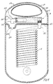
- the manual apparatus for water cleaning comprises a flattened housing 1, for instance with elliptical section, obtained with two semi-shells made of plastic material, anterior and posterior, 10 and 11, joined peripherally.
- a union fitting 5 for connection with the water supply line, which also constitutes an element for supporting the housing in projecting fashion from the wall.
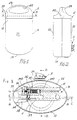
- the housing 1 has a closed bottom 13, preferably shaped according to a convex surface. Superiorly, the housing 1 has an opening 12 able to be closed with a conforming covering element 2.
- the covering element 2 inferiorly presents a base 20 ( Figures 4 and 5) and superiorly a vault 21, also obtained in two halves and provided with a window 22 to form a grip handle 23. Laterally, in the covering element 2 is provided an activating pushbutton 35, as illustrated hereafter.
- a water jet dispenser 3 connected by means of a hose 4 to the connection fitting 5.
- the dispenser 3 is situated in the base 20 of the covering element 2 and comprises an inlet fitting 30 passing through said base 20, a conduit 31 for the supply of a water flow, a valve 32 for shutting off said water flow and a beak 33.
- the shut off valve 32 is provided in the supply conduit 31 and controlled manually, through a lever 34, from the pushbutton 35.
- the lever 34 has a fork 340 oriented upwards which holds a transverse pivot rod 36 connected to a piston 37, ending with a shutter 370.
- the piston 37 movable against the action of a counter spring 38, serves to close the supply conduit 31 in its outlet segment 39 ending in the beak 33.
- Figure 4 which is a section obtained according to the line B-B of Figure 3, the beak 33 is curved downward and projects with its free end through an opening 24 obtained in the base 20 of the covering element 2.
- the base 20 is suitably shaped in its portion 200 to adapt to the beak 33.
- the hose 4 connected at one end to the inlet fitting and at the other end to the fitting 5 connecting to the water supply line, is spiral shaped, preferably made of rilsan (trade name), and able to withstand high pressures.
- connection fitting 5 connects the apparatus according to the present invention to the water supply line to supply water to the cleaning water jet dispenser.
- the connection fitting 5 comprises an element 50 for gripping the end of the hose 4, a tap 51 and a ball joint 52, 520.
- the tap 51 for instance with ball shutter, is arranged in such a way that its control lever 53 is accessible only from outside the housing 1, because it passes through its bottom 13.
- the wall of the housing is held between the tap 51 and the ball joint 52, 520 by means of sealing gaskets 54.
- the ball joint 52 is connected directly with threaded coupling to a water outlet 6, substantially elbow-shaped, appropriately provided in the wall 7, for instance, in a newly constructed bathroom.
- the ball joint 520 connected with threaded coupling of its pipe segment 81 on a support plate 9, fastened with screw anchors and screws 8 to a bathroom wall 7 comprising a closure tap, constitutes an element for supporting said housing in such a manner that it projects from the wall 7 of the bathroom.
- a T union fitting 80 for supplying water from a water outlet located distant from the location of the apparatus according to the invention.
- the covering element 2 is lifted from the opening on the housing 1 and approached to the hygienic vessel to be washed.
- the jet oriented on the hygienic vessel easily removes any faecal residues without causing any annoyance and inconvenience for the person performing the operation.
Landscapes
- Health & Medical Sciences (AREA)
- Public Health (AREA)
- Molecular Biology (AREA)
- Epidemiology (AREA)
- Life Sciences & Earth Sciences (AREA)
- Engineering & Computer Science (AREA)
- Hydrology & Water Resources (AREA)
- Water Supply & Treatment (AREA)
- Food-Manufacturing Devices (AREA)
- Cleaning In General (AREA)
- Apparatuses For Bulk Treatment Of Fruits And Vegetables And Apparatuses For Preparing Feeds (AREA)
- Cleaning By Liquid Or Steam (AREA)
Abstract
Description
- Figure 1 is a front view of the cleaning apparatus according to the present invention;
- Figure 2 is a lateral view of the cleaning apparatus of Figure 1;
- Figure 3 is a section obtained according to the line A-A of Figure 1;
- Figure 4 is a section obtained according to the line B-B of Figure 3;
- Figure 5 is a section obtained according to the line C-C of Figure 3;
- Figure 6 is a partial section obtained according to the line D-D of Figure 3 in the lower part of the cleaning apparatus according to the invention with a first example of wall mounted support;
- Figure 7 is a partial section obtained according to the line D-D of Figure 3 in the lower part of the cleaning apparatus according to the invention with a second example of wall mounted support.
Claims (4)
- A manual apparatus for cleaning a hygienic vessel with water, of the type comprising a housing (1) applied to a wall (7) of the bathroom adjacent to the vessel, an element (2) for covering said housing, a dispenser (3) of a water jet provided in said covering element (2), a hose (4) for supplying water secured on one side to said dispenser (3) and, on the other side, to a union fitting (5) connecting to the water supply line, characterised in thatsaid covering element (2) inferiorly presents a base (20) and superiorly a grip handle (23) for lifting and manoeuvring the water jet dispenser (3);said water jet dispenser (3), situated on said base (20) of the covering element (2), comprises an inlet fitting (30) passing through the base (20) of the covering element (2), a conduit (31) for supplying a water flow, a valve (32) for shutting off said water flow provided in said supply conduit (31) and controlled manually, through a lever (34), from a pushbutton (35) situated anteriorly in said covering element (2), a curved beak (33) oriented downwards and projecting with its free end through an opening (24) obtained in said base (20) of the covering element (2);said hose (4), connected at one end to said inlet fitting (30) and at the other end to the fitting (5) for connection to the water supply line, is shaped as a spiral;said connection fitting (5), comprising a closure tap (53), constitutes an element for supporting said housing (1) to the wall (7) of the bathroom.
- An apparatus as claimed in claim 1, characterised in that said spiral shaped hose (4) is made of rilsan (trade name).
- An apparatus as claimed in claim 1, characterised in that said connection fitting (5) comprises a ball joint (52) joined by means of threaded coupling to an elbow (6) of the water supply line passing through the wall (7) of the bathroom.
- An apparatus as claimed in claim 1, characterised in that said connection fitting (5) comprises a ball joint (520) provided with a pipe segment (81) joined by means of threaded coupling to a plate for fastening to the bathroom wall; said pipe segment (81) presenting a T fitting (8) for connection to the water supply line.
Applications Claiming Priority (2)
| Application Number | Priority Date | Filing Date | Title |
|---|---|---|---|
| ITRM990245U | 1999-11-18 | ||
| IT1999RM000245U IT247677Y1 (en) | 1999-11-18 | 1999-11-18 | MANUAL APPARATUS FOR HYDRO CLEANING OF A HYGIENIC POT. |
Publications (2)
| Publication Number | Publication Date |
|---|---|
| EP1101875A2 true EP1101875A2 (en) | 2001-05-23 |
| EP1101875A3 EP1101875A3 (en) | 2003-01-02 |
Family
ID=11406705
Family Applications (1)
| Application Number | Title | Priority Date | Filing Date |
|---|---|---|---|
| EP00830757A Withdrawn EP1101875A3 (en) | 1999-11-18 | 2000-11-16 | A manual apparatus for cleaning a hygienic vessel with water |
Country Status (3)
| Country | Link |
|---|---|
| US (1) | US6375097B1 (en) |
| EP (1) | EP1101875A3 (en) |
| IT (1) | IT247677Y1 (en) |
Cited By (1)
| Publication number | Priority date | Publication date | Assignee | Title |
|---|---|---|---|---|
| ES2220200A1 (en) * | 2002-12-26 | 2004-12-01 | Felix Moya Arribas | Toilet cleaning device, has hollow support attached with key through conduit, flexible conduit extending toward mounted brush that is equipped on tensile arm, and cleaning element equipped in end of brush |
Families Citing this family (1)
| Publication number | Priority date | Publication date | Assignee | Title |
|---|---|---|---|---|
| US9587391B1 (en) * | 2015-06-09 | 2017-03-07 | Nimrod Anderson | Wall-mounted cabinet having a bidet extendable there from |
Family Cites Families (7)
| Publication number | Priority date | Publication date | Assignee | Title |
|---|---|---|---|---|
| US2627074A (en) * | 1949-07-28 | 1953-02-03 | Karp Harry | Bathroom fixture |
| US3168984A (en) * | 1962-04-09 | 1965-02-09 | Advance Chemical Company | Container and apparatus for toilet bowl cleaning fluid |
| US4570855A (en) * | 1984-04-13 | 1986-02-18 | Johnston Taylor C | Spraying apparatus |
| US4670916A (en) * | 1985-11-20 | 1987-06-09 | Sitting Pretty, Inc. | Toilet bowl dispenser |
| DE3736406A1 (en) * | 1987-10-28 | 1989-05-24 | Heinz Georg Baus | MIXING DEVICE, IN PARTICULAR FOR SHOWERS OR BATHS |
| IT1277928B1 (en) * | 1995-09-04 | 1997-11-12 | Pietro Cestari | DEVICE WITH HYDRO-POWERED ROTATING BRUSH FOR THE INTERNAL CLEANING OF TOILETS AND SIMILAR |
| US5991937A (en) * | 1998-03-10 | 1999-11-30 | Safara; Stephen G | Bidet device |
-
1999
- 1999-11-18 IT IT1999RM000245U patent/IT247677Y1/en active
-
2000
- 2000-11-16 EP EP00830757A patent/EP1101875A3/en not_active Withdrawn
- 2000-11-17 US US09/714,116 patent/US6375097B1/en not_active Expired - Fee Related
Cited By (2)
| Publication number | Priority date | Publication date | Assignee | Title |
|---|---|---|---|---|
| ES2220200A1 (en) * | 2002-12-26 | 2004-12-01 | Felix Moya Arribas | Toilet cleaning device, has hollow support attached with key through conduit, flexible conduit extending toward mounted brush that is equipped on tensile arm, and cleaning element equipped in end of brush |
| ES2220200B1 (en) * | 2002-12-26 | 2006-02-16 | Felix Moya Arribas | TOILET CLEANING DEVICE. |
Also Published As
| Publication number | Publication date |
|---|---|
| ITRM990245V0 (en) | 1999-11-18 |
| EP1101875A3 (en) | 2003-01-02 |
| IT247677Y1 (en) | 2002-09-09 |
| US6375097B1 (en) | 2002-04-23 |
| ITRM990245U1 (en) | 2001-05-18 |
Similar Documents
| Publication | Publication Date | Title |
|---|---|---|
| US5720055A (en) | Cleaning and hygienic device | |
| AU2001285644B2 (en) | Device for controlling and/or regulating the supply of a medium, devices of this type comprising washing or drying units and a corresponding method | |
| KR200189623Y1 (en) | The structure of storage and drain for toilet bowl | |
| US6829787B1 (en) | Water saving dual flush system of valving | |
| US4750219A (en) | Urinal device | |
| WO1997016106A9 (en) | Cleaning and hygienic device | |
| US6375097B1 (en) | Manual apparatus for cleaning a hygienic vessel with water | |
| US20090300835A1 (en) | Air flush system | |
| US12071757B2 (en) | Toilet fixture | |
| RU2158336C1 (en) | Drain accessories | |
| AU2005273655B2 (en) | Urinal with hygienic sprinkler | |
| CN212772673U (en) | Toilet bowl | |
| EP1193352A1 (en) | A urinal applicable to toilet bowl | |
| CN209817014U (en) | Water level control and drainage device | |
| CN215211373U (en) | A pipe cleaning device | |
| US20060037129A1 (en) | Bidet attachment for toilets | |
| US12329328B1 (en) | Retrofittable waterless urinal assembly with odor control and method of installing and retrofitting using the same | |
| CN2491512Y (en) | Water saving safety active water sealed toilet | |
| CN106968308B (en) | Automatic toilet | |
| WO2023159287A1 (en) | Articulated siphon for toilets | |
| CN2575184Y (en) | UP-down public lavatories | |
| JPH0218128Y2 (en) | ||
| US6718564B2 (en) | Adapter for converting a flushometer valve to a water source | |
| CA2680498A1 (en) | Bidet/toilet spray faucet | |
| WO2005098151A1 (en) | Feeding/ flushing system for sanitary basins |
Legal Events
| Date | Code | Title | Description |
|---|---|---|---|
| PUAI | Public reference made under article 153(3) epc to a published international application that has entered the european phase |
Free format text: ORIGINAL CODE: 0009012 |
|
| AK | Designated contracting states |
Kind code of ref document: A2 Designated state(s): AT BE CH CY DE DK ES FI FR GB GR IE IT LI LU MC NL PT SE TR |
|
| AX | Request for extension of the european patent |
Free format text: AL;LT;LV;MK;RO;SI |
|
| PUAL | Search report despatched |
Free format text: ORIGINAL CODE: 0009013 |
|
| AK | Designated contracting states |
Kind code of ref document: A3 Designated state(s): AT BE CH CY DE DK ES FI FR GB GR IE IT LI LU MC NL PT SE TR |
|
| AX | Request for extension of the european patent |
Free format text: AL;LT;LV;MK;RO;SI |
|
| 17P | Request for examination filed |
Effective date: 20030627 |
|
| AKX | Designation fees paid |
Designated state(s): AT BE CH CY DE DK ES FI FR GB GR IE IT LI LU MC NL PT SE TR |
|
| STAA | Information on the status of an ep patent application or granted ep patent |
Free format text: STATUS: THE APPLICATION IS DEEMED TO BE WITHDRAWN |
|
| 18D | Application deemed to be withdrawn |
Effective date: 20050601 |