EP1101878A2 - Panneaux isolants de sous-toiture - Google Patents
Panneaux isolants de sous-toiture Download PDFInfo
- Publication number
- EP1101878A2 EP1101878A2 EP00119529A EP00119529A EP1101878A2 EP 1101878 A2 EP1101878 A2 EP 1101878A2 EP 00119529 A EP00119529 A EP 00119529A EP 00119529 A EP00119529 A EP 00119529A EP 1101878 A2 EP1101878 A2 EP 1101878A2
- Authority
- EP
- European Patent Office
- Prior art keywords
- thermal insulation
- insulation panel
- roof
- panels
- panel according
- Prior art date
- Legal status (The legal status is an assumption and is not a legal conclusion. Google has not performed a legal analysis and makes no representation as to the accuracy of the status listed.)
- Granted
Links
Images




Classifications
-
- E—FIXED CONSTRUCTIONS
- E04—BUILDING
- E04D—ROOF COVERINGS; SKY-LIGHTS; GUTTERS; ROOF-WORKING TOOLS
- E04D13/00—Special arrangements or devices in connection with roof coverings; Protection against birds; Roof drainage ; Sky-lights
- E04D13/16—Insulating devices or arrangements in so far as the roof covering is concerned, e.g. characterised by the material or composition of the roof insulating material or its integration in the roof structure
- E04D13/1606—Insulation of the roof covering characterised by its integration in the roof structure
- E04D13/1612—Insulation of the roof covering characterised by its integration in the roof structure the roof structure comprising a supporting framework of roof purlins or rafters
- E04D13/1618—Insulation of the roof covering characterised by its integration in the roof structure the roof structure comprising a supporting framework of roof purlins or rafters with means for fixing the insulating material between the roof covering and the upper surface of the roof purlins or rafters
-
- E—FIXED CONSTRUCTIONS
- E04—BUILDING
- E04D—ROOF COVERINGS; SKY-LIGHTS; GUTTERS; ROOF-WORKING TOOLS
- E04D12/00—Non-structural supports for roofing materials, e.g. battens, boards
Definitions
- the invention relates to thermal insulation boards for the sub-roof of a roof covered with roofing tiles, whereby the thermal insulation boards overlap each other on the Roof battens can be hooked in and knobs on their top have for hanging the roofing panels, and wherein in the eaves direction, the thermal insulation panels one each form a straight row, in which the thermal insulation panels to each other are not laterally offset.
- thermal insulation boards for one Known under the roof. They are laid offset from one another, which makes laying difficult and considerable Lots of waste is created.
- the object of the invention is to provide thermal insulation boards at the beginning to improve the type mentioned so that the thermal insulation boards with little waste and waste and uncomplicated Construction are easy and quick to install and a safe Ensure water drainage to the eaves. Is too it object of the invention the vulnerability of the thermal insulation boards against damage.
- the inclined side edge of the thermal insulation board a step-shaped Has recess that from the side of the neighboring thermal insulation board is overlapped and in its Top has a groove parallel to the side edge, which opens into a groove in the thermal insulation board underneath.
- Advantageous embodiments of the invention are in the Subclaims listed.
- the thermal insulation board 1 has a central part and runs to the ridge side 8 and 15 to the eaves side, whereby the length of the studs 12, for the roof battens, to the ridge side 8, on the underside B / D of the insulation board, is approximately the same length as the length on the Top of the insulation board A / C, between the receiving surface for roofing slabs, the upper one towards the ridge side Knob row 6 and the lower one in the direction of the eaves Plate edge 15.
- the underside 10 of the eaves-side plate part D and the top 7 of the ridge-side plate part A form in the covering flat system areas.
- the surface lies with the Support knobs 16 for the roof battens towards the center of the panel on the parallel edge of the ridge side (see Figure 1 and Figure 5).
- the surface 16 is opposite the central axis of the insulation board, in the direction from the board side A / C to plate side B / D, offset, see above that a flat, full-value edition on the in the ridge direction the top of the roof battens (see Figure 1 and Figure 4).
- the end of the bottom 13 of the upper part A / B ends with the Plant area 14 in the ridge direction as roof battens.
- the width of the surface 14 corresponds approximately to the width a roof batten.
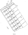
- Figure 2 shows the top of the lying in the ridge direction Thermal insulation board with side overlaps 18 and 24 for sealing the adjacent panels in side Direction.
- the angled side edges 19, with the lower left overlap in the ridge direction incorporated drainage channel 20, including the one-sided Outlet funnel 17, ensure the outflow of accruing Rain, thaw and condensation water on the surface of the left in the ridge direction, in the row below Thermal insulation board.
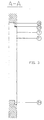
- FIG. 4 shows a roof covering plate 28 Under the roof of the type described on roof battens 26 and Rafters 25. It can be seen how the hanging knobs 29 of the roofing panels 28 on the lower row of knobs 2 with the receiving surface 3 and the upper row of knobs 5 rest with the mounting plate 6. It can also be seen like the lower studs for roof battens 12 the roof slat top 26 lying in the ridge direction rests. The variant shown is a double covering of roofing tiles.
- FIG 5 is the interaction of two thermal insulation boards shown in side view. This representation is meant to illustrate how the sealing of thermal insulation boards in Eaves; Ridge direction works.
- FIG. 6 shows and illustrates a thermal insulation board in 3D the spatial spread of a plate.
- the sub-roof thus consists of a slope and laterally overlapping on the top with two hanging knobs for the roofing slabs and on the underside with a hook-in knob for recording Thermal insulation panels provided with roof battens 1.
- the single thermal insulation panel is constructed so that it is approximately from the center from the most trained, to the eaves side as well also runs out in a wedge shape towards the ridge side.
- the top of the thermal insulation board is designed so that the upper part in the ridge direction for receiving and overlapping the one above, towards the ridge side Underside of the lower half of the insulation board and the lower half Part of the lower thermal insulation panel with two rows of nubs the inclusion of roofing slabs (single or double row) serves.
- the underside of the thermal insulation board is designed so that the upper part by means of the knob for hanging on the The top of the roof battens serves, the upper end to the ridge side lies on the roof batten above and the lower part for receiving and overlapping the eaves side Insulation boards are used.
- the sum of the length of the middle and the eaves side Part of the plate measured in the downward direction corresponds approximately to that Sum of the length of the middle and the ridge-side panel part, whose length corresponds approximately to the distance between the roof battens.
- the insulation boards are laid so that the Panels in the eaves-ridge direction and in the lateral direction are overlapping according to their function. This means, the thermal insulation boards are directed from the eaves side Ridge side and at the same time from the right roof side relocated to the left side of the roof.
- the dew, rain and condensed water that juxtaposed in the butt joints lying thermal insulation boards is on the underlying Thermal insulation board in the downward direction again headed the top of the insulation board.
- the distance between the studs for roofing slabs in the downward direction is designed so that both simple cover as well as a double cover with certain roofing tiles can be made.
- the thermal insulation board (1) runs from the center, which on strongest is wedge-shaped towards the edges.
- the ridge-side plate part goes through one Step on the top and the eaves-side plate part with the recording knobs for the one lying in the ridge direction Top of the roof battens in the middle section.
- the side panel edges are from the ridge side to arranged continuously to the eaves side. They are in the ridge direction seen, on the left side of the record in the lower Plate area and on the right side of the plate in the upper Plate area arranged.
- the size and shape of the thermal insulation board described Type is chosen so that the plate is easy to handle and is easy to install.
- the plate size is chosen so that a laying of roofing slabs on top of one another in the slope direction lying row of thermal insulation panels from the side is possible. So that is hanging roof ladders or entering the thermal insulation boards is not absolutely necessary.
- the Laying the panels no significant weak points in the total insulation. With just one plate shape it is possible cover an entire roof and slight differences equalize the distances between the roof battens. Larger batten distances are due to the wedge shape of the plates on which Underside of the top half of the plate and the top of the lower half of the panel and the panel surfaces in the ridge direction seen top of the upper half of the plate, and on the underside of the lower, seen in the ridge direction Half of the plate balanced so that when pulling the Thermal insulation boards in downward direction, within certain limits, always one for roofing tiles in the relative height flat contact surface is created.
- the side edges of the thermal insulation board are angled, see above that the overlap of two adjacent panels Seen in the ridge direction, always on the left side the surface, the thermal insulation board underneath in the ridge direction flows. This ensures that the Water flow from any rain, thaw and Condensed water that collects between two plate joints on the surface of the ridge below on the left lying thermal insulation panel and further derived to the eaves becomes.
- thermal insulation board is between the two rows of nubs A recess 4 to accommodate the roof covering panels incorporated a secure insert of a roof ladder, laid according to roofing rules, guaranteed.
- On the sub-roof of the type in question can be roofing tiles single-ply and with roofing panels provided for this purpose can also be laid in two layers.
- Roofs consist of eaves laid on roof tiles wide 7.10 and in the horizontal direction short 18.24 overlapping, with two in the lower part of the insulation boards the top of the C hanging stud rows 2.5 for the roofing tiles 28, which are in the executed form wedge-shaped from the center towards the edges in the ridge direction A, B and eaves direction C, D runs out.
- the middle of the plate has the greatest thickness (height, thickness) and runs in the upper part of panel A, B in the ridge direction approximately wedge-shaped to a lower thickness 8 out.
- thickness thickness
- the underside of the top plate B starts at strongest point with the recording knob 12 for Roof battens 26 and tapers in over the roof battens receiving surface 14 to surface 8 to surface 16 of the insulation board above.
- the lower part of the thermal insulation board in the direction of the eaves is on top C by two for roofing tiles rows of nubs 2.5 to be marked. There is one between the rows of knobs Recess 4 when laying roofing tiles 28 can be used to hold a roof ladder can. Tapered towards the plate edge 15 in the eaves direction the thermal insulation board to its lowest Strength.
- the lower side 10 of the lower plate part D is plan and serves as a support for the upper part A of the upper plate side 7 of the one above it in the ridge direction Plate.
- the surface 8 on the top of the plate lying in the ridge direction lies parallel to the surface of the roof slat receiving knob 12 and the surface 15 on the eaves lying bottom lies parallel to the surface 6 of the top roof covering stud.
- the side plate edges 19 are angled and form an obtuse angle R so that they placed next to each other with a perfect fit with the surfaces 18.24 overlap.
- the lateral overlaps are 18, 24 simple, robust and insensitive to damage, result in two panels overlapping side by side the same in every direction in the ridge and eaves direction Thickness, like the corresponding location of the sub-plate, along the side axis.
- the thermal insulation panels 1 have seen on average the entire installed roof area is the same throughout Strength on.
- the side edges 19 of the thermal insulation panels 1 are angled.
- the water drain in the downward direction to the eaves is guaranteed if the water drainage channels 21 including the outlet funnel 22.23 on the top of the thermal insulation panels be designed throughout. Minor bumps in the Roof battens and slight deviations in the roof battens spacing are normalized by the overlap of the Thermal insulation boards in the lateral direction 18.24 and in the slope direction 7.10 balanced.
- a water channel 20 with funnel-shaped outlet 17 incorporated on one side is. Collects when placing the thermal insulation panels possible condensation or rain or -Dew water between the bump of two side by side lying thermal insulation panels in the Water channel 20 and runs on one side funnel-shaped outlet 17 on the surface C recessed water guide and aeration channel 21, the thermal insulation board underneath in the direction of the eaves to the eaves.
- knobs 2.5 Through the two on the lower half of the top C located rows of knobs 2.5 can both the sub-roof single-layer as well as with roofing panels provided for this purpose, be covered in two layers.
Landscapes
- Engineering & Computer Science (AREA)
- Architecture (AREA)
- Civil Engineering (AREA)
- Structural Engineering (AREA)
- Roof Covering Using Slabs Or Stiff Sheets (AREA)
- Building Environments (AREA)
Applications Claiming Priority (2)
| Application Number | Priority Date | Filing Date | Title |
|---|---|---|---|
| DE19954836 | 1999-11-16 | ||
| DE19954836A DE19954836A1 (de) | 1999-11-16 | 1999-11-16 | Wärmedämmplatten für ein Unterdach |
Publications (3)
| Publication Number | Publication Date |
|---|---|
| EP1101878A2 true EP1101878A2 (fr) | 2001-05-23 |
| EP1101878A3 EP1101878A3 (fr) | 2001-08-08 |
| EP1101878B1 EP1101878B1 (fr) | 2005-04-20 |
Family
ID=7929062
Family Applications (1)
| Application Number | Title | Priority Date | Filing Date |
|---|---|---|---|
| EP00119529A Expired - Lifetime EP1101878B1 (fr) | 1999-11-16 | 2000-09-07 | Panneaux isolants de sous-toiture |
Country Status (3)
| Country | Link |
|---|---|
| EP (1) | EP1101878B1 (fr) |
| AT (1) | ATE293728T1 (fr) |
| DE (2) | DE19954836A1 (fr) |
Cited By (1)
| Publication number | Priority date | Publication date | Assignee | Title |
|---|---|---|---|---|
| GB2424426A (en) * | 2005-03-22 | 2006-09-27 | Lafarge Roofing Technical Centers Ltd | Insulated roof system |
Family Cites Families (6)
| Publication number | Priority date | Publication date | Assignee | Title |
|---|---|---|---|---|
| US3557180A (en) * | 1968-07-02 | 1971-01-19 | Du Pont | 2,4-bis(isocyanatocyclohexylmethyl) cyclohexyl isocyanate |
| DE2842347C2 (de) * | 1978-09-28 | 1982-08-19 | Thermodach Dachtechnik GmbH, 8598 Waldershof | Auf Dachsparren verlegbare Wärmedämmplatten |
| DE3403645A1 (de) * | 1984-02-02 | 1985-08-08 | Thermodach Dachtechnik GmbH, 8598 Waldershof | Ueber dachsparren verlegte waermedaemmplatten |
| DE3508631A1 (de) * | 1985-02-15 | 1986-08-21 | Helfrecht, Manfred, 8598 Waldershof | Waermedaemmelement fuer ein unterdach |
| DE3919511C1 (fr) * | 1989-06-15 | 1990-09-13 | Eugen 7084 Westhausen De Feil | |
| DE4424976C1 (de) * | 1994-07-15 | 1996-03-14 | Eugen Feil | Unterdach für mit Dacheindeckungsplatten eingedeckte Dächer |
-
1999
- 1999-11-16 DE DE19954836A patent/DE19954836A1/de not_active Withdrawn
-
2000
- 2000-09-07 DE DE50010095T patent/DE50010095D1/de not_active Expired - Fee Related
- 2000-09-07 EP EP00119529A patent/EP1101878B1/fr not_active Expired - Lifetime
- 2000-09-07 AT AT00119529T patent/ATE293728T1/de not_active IP Right Cessation
Cited By (1)
| Publication number | Priority date | Publication date | Assignee | Title |
|---|---|---|---|---|
| GB2424426A (en) * | 2005-03-22 | 2006-09-27 | Lafarge Roofing Technical Centers Ltd | Insulated roof system |
Also Published As
| Publication number | Publication date |
|---|---|
| EP1101878A3 (fr) | 2001-08-08 |
| ATE293728T1 (de) | 2005-05-15 |
| DE19954836A1 (de) | 2001-05-17 |
| DE50010095D1 (de) | 2005-05-25 |
| EP1101878B1 (fr) | 2005-04-20 |
Similar Documents
| Publication | Publication Date | Title |
|---|---|---|
| EP0257234B1 (fr) | Plaque de toiture pour engazonnement de toit | |
| EP0256263B1 (fr) | Sous-toiture pour toits recouverts par des panneaux de toits | |
| DE3214890C2 (fr) | ||
| DE2842347C2 (de) | Auf Dachsparren verlegbare Wärmedämmplatten | |
| DE2930898C2 (de) | Unterdach für mit Dacheindeckungsplatten eingedeckte Dächer | |
| DE1904484B2 (de) | Unterdach für mit Dacheindeckungsplatten eingedeckte Dächer | |
| DE3919511C1 (fr) | ||
| DE2349710C3 (fr) | ||
| EP1101878B1 (fr) | Panneaux isolants de sous-toiture | |
| EP0150865B1 (fr) | Panneaux d'isolation thermiques déposés sur des chevrons | |
| DE2349710B2 (de) | Unterdach | |
| DE3238861C2 (de) | Schrägdachkonstruktion | |
| DE3628188C2 (fr) | ||
| DE2842778C2 (de) | Wärmedämmplatte aus Hartschaumkunststoff | |
| DE3718613C2 (fr) | ||
| DE29923529U1 (de) | Wärmedämmplatten für ein Unterdach | |
| DE2305613C3 (de) | Unterdach | |
| DE2930385C2 (de) | Dacheindeckung | |
| DE3050863C2 (de) | Innenwärmedämmung für Dächer mit aus Profilplatten bestehenden Wärmedämmelementen | |
| DE4438331C2 (de) | Unterdachplatte | |
| DE2953539C2 (de) | Dacheindeckung | |
| EP0898029A2 (fr) | Couverture circulable pour un toit plat ou une terrasse | |
| DE3040183C2 (de) | Unterdach | |
| AT390985B (de) | Wasserfuehrungssystem fuer ein unterdach | |
| DE4414918A1 (de) | Wasserführende Falz- und Überlappungskonstruktion für ein Unterdach |
Legal Events
| Date | Code | Title | Description |
|---|---|---|---|
| PUAI | Public reference made under article 153(3) epc to a published international application that has entered the european phase |
Free format text: ORIGINAL CODE: 0009012 |
|
| AK | Designated contracting states |
Kind code of ref document: A2 Designated state(s): AT BE CH CY DE DK ES FI FR GB GR IE IT LI LU MC NL PT SE |
|
| AX | Request for extension of the european patent |
Free format text: AL;LT;LV;MK;RO;SI |
|
| PUAL | Search report despatched |
Free format text: ORIGINAL CODE: 0009013 |
|
| AK | Designated contracting states |
Kind code of ref document: A3 Designated state(s): AT BE CH CY DE DK ES FI FR GB GR IE IT LI LU MC NL PT SE |
|
| AX | Request for extension of the european patent |
Free format text: AL;LT;LV;MK;RO;SI |
|
| 17P | Request for examination filed |
Effective date: 20011213 |
|
| AKX | Designation fees paid |
Free format text: AT BE CH CY DE DK ES FI FR GB GR IE IT LI LU MC NL PT SE |
|
| 17Q | First examination report despatched |
Effective date: 20040109 |
|
| GRAP | Despatch of communication of intention to grant a patent |
Free format text: ORIGINAL CODE: EPIDOSNIGR1 |
|
| GRAS | Grant fee paid |
Free format text: ORIGINAL CODE: EPIDOSNIGR3 |
|
| GRAA | (expected) grant |
Free format text: ORIGINAL CODE: 0009210 |
|
| AK | Designated contracting states |
Kind code of ref document: B1 Designated state(s): AT BE CH CY DE DK ES FI FR GB GR IE IT LI LU MC NL PT SE |
|
| PG25 | Lapsed in a contracting state [announced via postgrant information from national office to epo] |
Ref country code: IT Free format text: LAPSE BECAUSE OF FAILURE TO SUBMIT A TRANSLATION OF THE DESCRIPTION OR TO PAY THE FEE WITHIN THE PRESCRIBED TIME-LIMIT;WARNING: LAPSES OF ITALIAN PATENTS WITH EFFECTIVE DATE BEFORE 2007 MAY HAVE OCCURRED AT ANY TIME BEFORE 2007. THE CORRECT EFFECTIVE DATE MAY BE DIFFERENT FROM THE ONE RECORDED. Effective date: 20050420 Ref country code: GB Free format text: LAPSE BECAUSE OF FAILURE TO SUBMIT A TRANSLATION OF THE DESCRIPTION OR TO PAY THE FEE WITHIN THE PRESCRIBED TIME-LIMIT Effective date: 20050420 Ref country code: FI Free format text: LAPSE BECAUSE OF FAILURE TO SUBMIT A TRANSLATION OF THE DESCRIPTION OR TO PAY THE FEE WITHIN THE PRESCRIBED TIME-LIMIT Effective date: 20050420 Ref country code: NL Free format text: LAPSE BECAUSE OF FAILURE TO SUBMIT A TRANSLATION OF THE DESCRIPTION OR TO PAY THE FEE WITHIN THE PRESCRIBED TIME-LIMIT Effective date: 20050420 Ref country code: IE Free format text: LAPSE BECAUSE OF FAILURE TO SUBMIT A TRANSLATION OF THE DESCRIPTION OR TO PAY THE FEE WITHIN THE PRESCRIBED TIME-LIMIT Effective date: 20050420 |
|
| REG | Reference to a national code |
Ref country code: GB Ref legal event code: FG4D Free format text: NOT ENGLISH |
|
| REG | Reference to a national code |
Ref country code: CH Ref legal event code: NV Representative=s name: SCHMAUDER & PARTNER AG PATENTANWALTSBUERO Ref country code: CH Ref legal event code: EP |
|
| REG | Reference to a national code |
Ref country code: IE Ref legal event code: FG4D Free format text: LANGUAGE OF EP DOCUMENT: GERMAN |
|
| REF | Corresponds to: |
Ref document number: 50010095 Country of ref document: DE Date of ref document: 20050525 Kind code of ref document: P |
|
| PG25 | Lapsed in a contracting state [announced via postgrant information from national office to epo] |
Ref country code: DK Free format text: LAPSE BECAUSE OF FAILURE TO SUBMIT A TRANSLATION OF THE DESCRIPTION OR TO PAY THE FEE WITHIN THE PRESCRIBED TIME-LIMIT Effective date: 20050720 Ref country code: GR Free format text: LAPSE BECAUSE OF FAILURE TO SUBMIT A TRANSLATION OF THE DESCRIPTION OR TO PAY THE FEE WITHIN THE PRESCRIBED TIME-LIMIT Effective date: 20050720 Ref country code: SE Free format text: LAPSE BECAUSE OF FAILURE TO SUBMIT A TRANSLATION OF THE DESCRIPTION OR TO PAY THE FEE WITHIN THE PRESCRIBED TIME-LIMIT Effective date: 20050720 |
|
| PG25 | Lapsed in a contracting state [announced via postgrant information from national office to epo] |
Ref country code: ES Free format text: LAPSE BECAUSE OF FAILURE TO SUBMIT A TRANSLATION OF THE DESCRIPTION OR TO PAY THE FEE WITHIN THE PRESCRIBED TIME-LIMIT Effective date: 20050731 |
|
| PG25 | Lapsed in a contracting state [announced via postgrant information from national office to epo] |
Ref country code: CY Free format text: LAPSE BECAUSE OF FAILURE TO SUBMIT A TRANSLATION OF THE DESCRIPTION OR TO PAY THE FEE WITHIN THE PRESCRIBED TIME-LIMIT Effective date: 20050907 |
|
| PG25 | Lapsed in a contracting state [announced via postgrant information from national office to epo] |
Ref country code: PT Free format text: LAPSE BECAUSE OF FAILURE TO SUBMIT A TRANSLATION OF THE DESCRIPTION OR TO PAY THE FEE WITHIN THE PRESCRIBED TIME-LIMIT Effective date: 20050920 |
|
| PG25 | Lapsed in a contracting state [announced via postgrant information from national office to epo] |
Ref country code: MC Free format text: LAPSE BECAUSE OF NON-PAYMENT OF DUE FEES Effective date: 20050930 Ref country code: LU Free format text: LAPSE BECAUSE OF NON-PAYMENT OF DUE FEES Effective date: 20050930 Ref country code: BE Free format text: LAPSE BECAUSE OF NON-PAYMENT OF DUE FEES Effective date: 20050930 |
|
| NLV1 | Nl: lapsed or annulled due to failure to fulfill the requirements of art. 29p and 29m of the patents act | ||
| GBV | Gb: ep patent (uk) treated as always having been void in accordance with gb section 77(7)/1977 [no translation filed] |
Effective date: 20050420 |
|
| REG | Reference to a national code |
Ref country code: IE Ref legal event code: FD4D |
|
| PLBE | No opposition filed within time limit |
Free format text: ORIGINAL CODE: 0009261 |
|
| STAA | Information on the status of an ep patent application or granted ep patent |
Free format text: STATUS: NO OPPOSITION FILED WITHIN TIME LIMIT |
|
| ET | Fr: translation filed | ||
| 26N | No opposition filed |
Effective date: 20060123 |
|
| PGFP | Annual fee paid to national office [announced via postgrant information from national office to epo] |
Ref country code: DE Payment date: 20070830 Year of fee payment: 8 |
|
| PGFP | Annual fee paid to national office [announced via postgrant information from national office to epo] |
Ref country code: AT Payment date: 20070912 Year of fee payment: 8 Ref country code: CH Payment date: 20070830 Year of fee payment: 8 |
|
| BERE | Be: lapsed |
Owner name: HERR, JOACHIM WOLFRAM Effective date: 20050930 |
|
| PGFP | Annual fee paid to national office [announced via postgrant information from national office to epo] |
Ref country code: FR Payment date: 20070914 Year of fee payment: 8 |
|
| REG | Reference to a national code |
Ref country code: CH Ref legal event code: PL |
|
| REG | Reference to a national code |
Ref country code: FR Ref legal event code: ST Effective date: 20090529 |
|
| PG25 | Lapsed in a contracting state [announced via postgrant information from national office to epo] |
Ref country code: DE Free format text: LAPSE BECAUSE OF NON-PAYMENT OF DUE FEES Effective date: 20090401 Ref country code: AT Free format text: LAPSE BECAUSE OF NON-PAYMENT OF DUE FEES Effective date: 20080907 |
|
| PG25 | Lapsed in a contracting state [announced via postgrant information from national office to epo] |
Ref country code: FR Free format text: LAPSE BECAUSE OF NON-PAYMENT OF DUE FEES Effective date: 20080930 Ref country code: CH Free format text: LAPSE BECAUSE OF NON-PAYMENT OF DUE FEES Effective date: 20080930 Ref country code: LI Free format text: LAPSE BECAUSE OF NON-PAYMENT OF DUE FEES Effective date: 20080930 |