EP1101879A1 - Gitterträger - Google Patents
Gitterträger Download PDFInfo
- Publication number
- EP1101879A1 EP1101879A1 EP00420197A EP00420197A EP1101879A1 EP 1101879 A1 EP1101879 A1 EP 1101879A1 EP 00420197 A EP00420197 A EP 00420197A EP 00420197 A EP00420197 A EP 00420197A EP 1101879 A1 EP1101879 A1 EP 1101879A1
- Authority
- EP
- European Patent Office
- Prior art keywords
- loops
- planes
- head
- secured
- lattice
- Prior art date
- Legal status (The legal status is an assumption and is not a legal conclusion. Google has not performed a legal analysis and makes no representation as to the accuracy of the status listed.)
- Granted
Links
Images

Classifications
-
- E—FIXED CONSTRUCTIONS
- E04—BUILDING
- E04C—STRUCTURAL ELEMENTS; BUILDING MATERIALS
- E04C5/00—Reinforcing elements, e.g. for concrete; Auxiliary elements therefor
- E04C5/01—Reinforcing elements of metal, e.g. with non-structural coatings
- E04C5/06—Reinforcing elements of metal, e.g. with non-structural coatings of high bending resistance, i.e. of essentially three-dimensional [3D] extent, e.g. lattice girders
- E04C5/065—Light-weight girders, e.g. with precast parts
-
- E—FIXED CONSTRUCTIONS
- E04—BUILDING
- E04C—STRUCTURAL ELEMENTS; BUILDING MATERIALS
- E04C5/00—Reinforcing elements, e.g. for concrete; Auxiliary elements therefor
- E04C5/01—Reinforcing elements of metal, e.g. with non-structural coatings
- E04C5/02—Reinforcing elements of metal, e.g. with non-structural coatings of low bending resistance, i.e. of essentially one-dimensional [1D] or two-dimensional [2D] extent
Definitions
- the invention relates to a truss beam or truss, intended to be used. in the field of building, and more particularly in the field of the realization of prefabricated floors.
- Lattice beams are well known and are for example described in the document EP-A-0 465 776. They are generally used to make reinforced concrete floors made of beams and concrete or polystyrene interjoists.
- the truss beam described in the aforementioned document typically comprises two sinusoids or zigzag or diagonal rods, constituting trellis planes, secured at the level of streaks.
- the upper loops of the trellis planes are secured to an upper strand, in particular in the vicinity of the end of their loops upper, and the lower loops are secured in the vicinity of their end at lower streak level.
- these beams are unsuitable for crossing large spans without prop or equivalent support device, which proves harmful for certain applications, in particular for crawl space floors where art processes previous propose beams of more than four meters without requiring shoring.
- the object of the invention is to propose a production truss beam or truss easy, easy to set up, likely to develop mechanical characteristics suitable for overcoming the installation of props, without requiring a significant reinforcement of the materials used for the realization of the concrete pad which coats the basic steels and serves as a support for interjoists.
- the mussels, the whole transformation process and the final appearance of the product remain unchanged.
- This truss or truss comprises two trellis planes in the form of loops successive, secured to three linear rods acting as threads, respectively a head line and two base lines, these two trellis planes being inclined relative to at the bisector of the angle defined by the three threads.
- Each of the trellis planes is secured to the leading edge near the end of the upper loops which constitute them.
- Each of the trellis planes is secured to only one of the basic strands in the vicinity of the end of the lower loops, said planes being secured at the level of the face internal of said streaks.
- the beam according to the invention is characterized in that the upper loops are flared or flattened at the level of their area of attachment to the head thread, so as to increase the distance separating the two zones of effective attachment of the same loop at said head thread, the end of said loops extending slightly beyond the headline to which they are attached.
- the upper loops are wider, and wider than the lower loops.
- the buckling length of the upper struts is reduced, in particular between the joining areas of the trellis planes.
- the nodes i.e. the points of joining formed by the flattened upper loops of the trellis planes and the stringing higher, are spaced several centimeters apart, and thereby confer greater rigidity to this fixation of the upper rod. This provides improved maintenance of steel or upper thread.
- These links then function as real recesses and no longer as joints.
- the upper loops of the trellis planes then become very flattened, they participate in the compression effort, thereby reducing the compression stresses generated at the headline in the part inside the loop.
- this compression participates in the shortening of said head thread, so that the deflection of the beam is also reduced.
- the beam is symmetrical with respect to the plane angle bisector formed by the threads.
- the headline is in fact made up of two ropes, positioned one below the other and one in contact with the other, and at the level which is secured to each of the upper loops of said lattice planes.
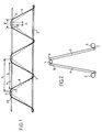
- FIG. 1 is a side view of a first embodiment of the invention, of which Figure 2 is a schematic representation in cross section.
- FIG. 3 is a schematic perspective representation of the beam in FIGS. 1 and 2.
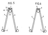
- Figure 4 is a view similar to Figure 1 of a second embodiment of the invention, of which Figures 5 and 6 are schematic representations in cross section.
- FIG. 1 a schematic side view of the beam according to the invention.
- This beam is basically made up of three streaks rectilinear, respectively a head line (1) and two base lines (2) and (3), these different struts being advantageously made of stainless steel.
- These strings are secured by means of lateral trellis planes (4) and (5).
- These plans of trellises each consist of a succession of loops or sinusoids, diagonals or zigzags, mounted in the same plane, and extending slightly obliquely by relation to the bisector plane of the beam thus formed.
- the upper loops (6) of the planes of trellis are flared, so as to optimize the length 1, respectively the, called installation length, separating the contact points (10, 11) and in particular of securing of the loops (6) at the level of the head thread (1).
- the admissible compressive force is increased because part of said force is transmitted to the upper loops of the two trellis planes, and therefore we decrease the compressive stresses at the level of the steel making up the head thread (1), including the part inside the loop.
- the upper chord is made up not of one but of two steel bars (1, 8), in order to increase the inertia of the beam and as a corollary to decrease the deflection when it is loaded.
- these two bars are in contact one from the other, the lower bar (8) having a diameter greater than the thread (1), so as to occupy all the space available at this level between the two trellis planes antagonists.
- the upper loops are joined, in particular by welding to each of the two streaks (1, 8).
- the two strands are unrolled simultaneously continuously on machines automatic and welded by resistance to the two trellis planes, and this, over the entire length of the beam.
- the buckling length of the lower strand (8) is reduced compared to that of the strand upper (1) of smaller diameter, due to its larger diameter, giving it greater resistance to buckling. Furthermore, given the joined nature of the two upper strands, the lower strand (8) prevents vertical buckling of the strand upper (1).
- the straight bars of the trellis and in particular the basic strands (2) and (3), the buckling length of which is also shortened.
- the two diagonal welds on the two head bars increase the rigidity of this assembly and also transform it into recess. It follows an increase of the buckling breaking load of these diagonals.
- the overall resistance of the beam is also increased. As a corollary, the resistance to the shear force of the beam, this being limited by the load causing the buckling of the trellis wires and by the resistance of the welds.
- the upper loops (6) are secured to the two ropes (1) and (8) by welding. In this way, the compression effect is optimized as well generates.
- said head thread is in fact made up that of a single element (9), but has a complex shape in section in eight of figure, the bottom loop of which is larger in diameter than the bottom loop top, as can be seen for example in Figure 6.
- the upper loops (6) are secured at each of the two loops constituting said eight.
- This shape aims to give the same characteristics, in particular mechanical, to the streak and leaving with the beam.
- the trellis planes are symmetrical to each other by relative to the bisector plane of the beam.
- the lower loops of the trellis planes are much less flared than the upper loops, as they are intended to be embedded in the concrete pad which brings the embedding characteristics to the diagonals of the trellis.
- the span without forestay or the distances between struts of beams or lattice girders produced in accordance with the invention are found strongly improved by the new geometry of said beams and by the increase in mechanical characteristics, in particular head threads and diagonals.
Landscapes
- Engineering & Computer Science (AREA)
- Architecture (AREA)
- Civil Engineering (AREA)
- Structural Engineering (AREA)
- Rod-Shaped Construction Members (AREA)
- Reinforcement Elements For Buildings (AREA)
- Holo Graphy (AREA)
- Telescopes (AREA)
- Revetment (AREA)
- Paper (AREA)
Applications Claiming Priority (2)
| Application Number | Priority Date | Filing Date | Title |
|---|---|---|---|
| FR9914578 | 1999-11-19 | ||
| FR9914578A FR2801330B1 (fr) | 1999-11-19 | 1999-11-19 | Poutre en treillis |
Publications (2)
| Publication Number | Publication Date |
|---|---|
| EP1101879A1 true EP1101879A1 (de) | 2001-05-23 |
| EP1101879B1 EP1101879B1 (de) | 2004-01-21 |
Family
ID=9552307
Family Applications (1)
| Application Number | Title | Priority Date | Filing Date |
|---|---|---|---|
| EP00420197A Expired - Lifetime EP1101879B1 (de) | 1999-11-19 | 2000-09-26 | Gitterträger |
Country Status (5)
| Country | Link |
|---|---|
| EP (1) | EP1101879B1 (de) |
| AT (1) | ATE258258T1 (de) |
| DE (1) | DE60007824T2 (de) |
| ES (1) | ES2211486T3 (de) |
| FR (1) | FR2801330B1 (de) |
Cited By (2)
| Publication number | Priority date | Publication date | Assignee | Title |
|---|---|---|---|---|
| GB2488821A (en) * | 2011-03-10 | 2012-09-12 | John Christopher Holt | Multi element truss for structural panel |
| CN110629917A (zh) * | 2019-09-20 | 2019-12-31 | 中国五冶集团有限公司 | 一种楼层板结构 |
Families Citing this family (1)
| Publication number | Priority date | Publication date | Assignee | Title |
|---|---|---|---|---|
| DE102005006449B4 (de) * | 2005-02-12 | 2008-01-31 | Syspro-Gruppe Betonbauteile E.V. | Gitterträger für ein aus Betonfertigplatten bestehendes Wandelement |
Citations (8)
| Publication number | Priority date | Publication date | Assignee | Title |
|---|---|---|---|---|
| FR1234326A (fr) * | 1958-06-11 | 1960-10-17 | Bottiger & Co | Poutre soudée pour le montage de planchers et procédé pour sa fabrication |
| DE1936683A1 (de) * | 1968-07-22 | 1970-01-29 | Oesterr Alpine Montan | Bewehrungsstahl |
| DE2329943A1 (de) * | 1973-06-13 | 1975-01-09 | Rheinbau Gmbh | Gittertraeger |
| WO1980001818A1 (fr) * | 1979-02-27 | 1980-09-04 | F Bucher | Armature pour beton arme et procede pour sa fabrication |
| EP0339018A1 (de) * | 1988-04-22 | 1989-10-25 | "FER" FERTIGTEIL- ENTWICKLUNGS-RING GESELLSCHAFT M.B.H. & Co. K.G. | Gitterträger für die Herstellung von teilweise vorgefertigten Stahlbetondecken |
| EP0465777A1 (de) * | 1990-07-12 | 1992-01-15 | BADISCHE DRAHTWERKE GmbH | Gitterträger |
| FR2736954A1 (fr) * | 1995-07-20 | 1997-01-24 | Cote Francois Georges Albert | Amenagement structurel applique aux armatures a treillis metalliques soudes, pour ameliorer leur raideur longitudinale |
| FR2752257A1 (fr) * | 1996-08-08 | 1998-02-13 | Prod Speciaux D Isolation P S | Systeme d'isolation de planchers beton comportant des poutrelles en treillis metallique |
-
1999
- 1999-11-19 FR FR9914578A patent/FR2801330B1/fr not_active Expired - Lifetime
-
2000
- 2000-09-26 EP EP00420197A patent/EP1101879B1/de not_active Expired - Lifetime
- 2000-09-26 ES ES00420197T patent/ES2211486T3/es not_active Expired - Lifetime
- 2000-09-26 AT AT00420197T patent/ATE258258T1/de not_active IP Right Cessation
- 2000-09-26 DE DE60007824T patent/DE60007824T2/de not_active Expired - Lifetime
Patent Citations (8)
| Publication number | Priority date | Publication date | Assignee | Title |
|---|---|---|---|---|
| FR1234326A (fr) * | 1958-06-11 | 1960-10-17 | Bottiger & Co | Poutre soudée pour le montage de planchers et procédé pour sa fabrication |
| DE1936683A1 (de) * | 1968-07-22 | 1970-01-29 | Oesterr Alpine Montan | Bewehrungsstahl |
| DE2329943A1 (de) * | 1973-06-13 | 1975-01-09 | Rheinbau Gmbh | Gittertraeger |
| WO1980001818A1 (fr) * | 1979-02-27 | 1980-09-04 | F Bucher | Armature pour beton arme et procede pour sa fabrication |
| EP0339018A1 (de) * | 1988-04-22 | 1989-10-25 | "FER" FERTIGTEIL- ENTWICKLUNGS-RING GESELLSCHAFT M.B.H. & Co. K.G. | Gitterträger für die Herstellung von teilweise vorgefertigten Stahlbetondecken |
| EP0465777A1 (de) * | 1990-07-12 | 1992-01-15 | BADISCHE DRAHTWERKE GmbH | Gitterträger |
| FR2736954A1 (fr) * | 1995-07-20 | 1997-01-24 | Cote Francois Georges Albert | Amenagement structurel applique aux armatures a treillis metalliques soudes, pour ameliorer leur raideur longitudinale |
| FR2752257A1 (fr) * | 1996-08-08 | 1998-02-13 | Prod Speciaux D Isolation P S | Systeme d'isolation de planchers beton comportant des poutrelles en treillis metallique |
Cited By (3)
| Publication number | Priority date | Publication date | Assignee | Title |
|---|---|---|---|---|
| GB2488821A (en) * | 2011-03-10 | 2012-09-12 | John Christopher Holt | Multi element truss for structural panel |
| GB2488821B (en) * | 2011-03-10 | 2017-02-15 | Christopher Holt John | Truss |
| CN110629917A (zh) * | 2019-09-20 | 2019-12-31 | 中国五冶集团有限公司 | 一种楼层板结构 |
Also Published As
| Publication number | Publication date |
|---|---|
| ES2211486T3 (es) | 2004-07-16 |
| FR2801330B1 (fr) | 2002-05-31 |
| FR2801330A1 (fr) | 2001-05-25 |
| EP1101879B1 (de) | 2004-01-21 |
| DE60007824T2 (de) | 2004-12-02 |
| DE60007824D1 (de) | 2004-02-26 |
| ATE258258T1 (de) | 2004-02-15 |
Similar Documents
| Publication | Publication Date | Title |
|---|---|---|
| EP0288350B1 (de) | Brücke, bestehend aus einem Deck und dessen Trägern, insbesondere Schrägseilbrücke und Verfahren zu ihrer Herstellung | |
| FR2637930A1 (fr) | Procede pour la realisation de structure metallique notamment pour la couverture | |
| FR2669714A1 (fr) | Poutrelle profilee creuse. | |
| EP0329517B1 (de) | Schrägkabelbrücke und Verfahren zu deren Bau | |
| EP1101879B1 (de) | Gitterträger | |
| FR3078863A1 (fr) | Structure de rampe de pulverisation ou d'epandage et pulverisateur ou epandeur avec une telle rampe | |
| EP0454575A1 (de) | Fahrbahnplatte für Brücken, insbesondere für Brücken mit grosser Spannweite | |
| CH694375A5 (fr) | Armature flexible de connexion reliant les armatures d'une structure en béton. | |
| FR2693492A1 (fr) | Pont haubanné et son procédé de réalisation. | |
| EP4168638B1 (de) | Schalung mit verbesserter duktilität mit faltbarem dreidimensionalem bewehrungskäfig | |
| EP0126011B1 (de) | Verfahren zur Herstellung von hohlen Elementen wie etwa Leitungen, Silos oder Bunkern | |
| JP6909561B2 (ja) | 柱梁の接合構造 | |
| FR2812310A1 (fr) | Longeron de pont prefabrique et procede de fabrication d'un tel pont | |
| FR2600358A2 (fr) | Poutres en beton arme et en acier de grande portee | |
| EP0242238A1 (de) | Stahl- und bewehrte Betonkonstruktionen, insbesondere zur Trägerherstellung, insbesondere als Dachbalken benutzbarer Träger oder Träger mit grosser Spannweite | |
| FR2599070A2 (fr) | Liaison metallique rigide entre planchers-dalles levees et poteaux prefabriques en beton arme pour structures autostables | |
| FR2907826A1 (fr) | Pylone de telecommunication | |
| FR2865753A1 (fr) | Plate-forme de securite et construction comportant une telle plate-forme. | |
| EP0167425B1 (de) | Vorrichtung zum Befestigen von Abspannseilen an einem Mast und Mast mit einer solchen Vorrichtung | |
| EP1418283A1 (de) | Modulare Trägerstruktur | |
| FR2593536A1 (fr) | Structures en beton arme et en acier, notamment pour realiser des poutres et, en particulier, des poutres a usage de pannes. | |
| EP0953684B1 (de) | Fachwerkträger und Brücke mit einem derartigen Träger | |
| BE637136A (de) | ||
| FR3012157A1 (fr) | Armature passive et construction comportant une telle armature | |
| EP1162314A1 (de) | Verbindungsvorrichtung für ein Metallrohr und einen Träger oder eine Decke aus Beton |
Legal Events
| Date | Code | Title | Description |
|---|---|---|---|
| PUAI | Public reference made under article 153(3) epc to a published international application that has entered the european phase |
Free format text: ORIGINAL CODE: 0009012 |
|
| AK | Designated contracting states |
Kind code of ref document: A1 Designated state(s): AT BE CH CY DE DK ES FI FR GB GR IE IT LI LU MC NL PT SE |
|
| AX | Request for extension of the european patent |
Free format text: AL;LT;LV;MK;RO;SI |
|
| 17P | Request for examination filed |
Effective date: 20010716 |
|
| AKX | Designation fees paid |
Free format text: AT BE CH CY DE DK ES FI FR GB GR IE IT LI LU MC NL PT SE |
|
| 17Q | First examination report despatched |
Effective date: 20030331 |
|
| GRAP | Despatch of communication of intention to grant a patent |
Free format text: ORIGINAL CODE: EPIDOSNIGR1 |
|
| GRAS | Grant fee paid |
Free format text: ORIGINAL CODE: EPIDOSNIGR3 |
|
| GRAA | (expected) grant |
Free format text: ORIGINAL CODE: 0009210 |
|
| AK | Designated contracting states |
Kind code of ref document: B1 Designated state(s): AT BE CH CY DE DK ES FI FR GB GR IE IT LI LU MC NL PT SE |
|
| PG25 | Lapsed in a contracting state [announced via postgrant information from national office to epo] |
Ref country code: GB Free format text: LAPSE BECAUSE OF FAILURE TO SUBMIT A TRANSLATION OF THE DESCRIPTION OR TO PAY THE FEE WITHIN THE PRESCRIBED TIME-LIMIT Effective date: 20040121 Ref country code: AT Free format text: LAPSE BECAUSE OF FAILURE TO SUBMIT A TRANSLATION OF THE DESCRIPTION OR TO PAY THE FEE WITHIN THE PRESCRIBED TIME-LIMIT Effective date: 20040121 Ref country code: FI Free format text: LAPSE BECAUSE OF FAILURE TO SUBMIT A TRANSLATION OF THE DESCRIPTION OR TO PAY THE FEE WITHIN THE PRESCRIBED TIME-LIMIT Effective date: 20040121 Ref country code: CY Free format text: LAPSE BECAUSE OF FAILURE TO SUBMIT A TRANSLATION OF THE DESCRIPTION OR TO PAY THE FEE WITHIN THE PRESCRIBED TIME-LIMIT Effective date: 20040121 Ref country code: NL Free format text: LAPSE BECAUSE OF FAILURE TO SUBMIT A TRANSLATION OF THE DESCRIPTION OR TO PAY THE FEE WITHIN THE PRESCRIBED TIME-LIMIT Effective date: 20040121 Ref country code: IE Free format text: LAPSE BECAUSE OF FAILURE TO SUBMIT A TRANSLATION OF THE DESCRIPTION OR TO PAY THE FEE WITHIN THE PRESCRIBED TIME-LIMIT Effective date: 20040121 |
|
| REG | Reference to a national code |
Ref country code: GB Ref legal event code: FG4D Free format text: NOT ENGLISH |
|
| REG | Reference to a national code |
Ref country code: CH Ref legal event code: EP |
|
| REG | Reference to a national code |
Ref country code: IE Ref legal event code: FG4D Free format text: FRENCH |
|
| REF | Corresponds to: |
Ref document number: 60007824 Country of ref document: DE Date of ref document: 20040226 Kind code of ref document: P |
|
| PG25 | Lapsed in a contracting state [announced via postgrant information from national office to epo] |
Ref country code: GR Free format text: LAPSE BECAUSE OF FAILURE TO SUBMIT A TRANSLATION OF THE DESCRIPTION OR TO PAY THE FEE WITHIN THE PRESCRIBED TIME-LIMIT Effective date: 20040421 Ref country code: SE Free format text: LAPSE BECAUSE OF FAILURE TO SUBMIT A TRANSLATION OF THE DESCRIPTION OR TO PAY THE FEE WITHIN THE PRESCRIBED TIME-LIMIT Effective date: 20040421 Ref country code: DK Free format text: LAPSE BECAUSE OF FAILURE TO SUBMIT A TRANSLATION OF THE DESCRIPTION OR TO PAY THE FEE WITHIN THE PRESCRIBED TIME-LIMIT Effective date: 20040421 |
|
| NLV1 | Nl: lapsed or annulled due to failure to fulfill the requirements of art. 29p and 29m of the patents act | ||
| REG | Reference to a national code |
Ref country code: ES Ref legal event code: FG2A Ref document number: 2211486 Country of ref document: ES Kind code of ref document: T3 |
|
| GBV | Gb: ep patent (uk) treated as always having been void in accordance with gb section 77(7)/1977 [no translation filed] |
Effective date: 20040121 |
|
| REG | Reference to a national code |
Ref country code: IE Ref legal event code: FD4D |
|
| PG25 | Lapsed in a contracting state [announced via postgrant information from national office to epo] |
Ref country code: MC Free format text: LAPSE BECAUSE OF NON-PAYMENT OF DUE FEES Effective date: 20040930 |
|
| PLBE | No opposition filed within time limit |
Free format text: ORIGINAL CODE: 0009261 |
|
| STAA | Information on the status of an ep patent application or granted ep patent |
Free format text: STATUS: NO OPPOSITION FILED WITHIN TIME LIMIT |
|
| 26N | No opposition filed |
Effective date: 20041022 |
|
| PG25 | Lapsed in a contracting state [announced via postgrant information from national office to epo] |
Ref country code: PT Free format text: LAPSE BECAUSE OF NON-PAYMENT OF DUE FEES Effective date: 20040621 |
|
| PGFP | Annual fee paid to national office [announced via postgrant information from national office to epo] |
Ref country code: DE Payment date: 20100910 Year of fee payment: 11 |
|
| PGFP | Annual fee paid to national office [announced via postgrant information from national office to epo] |
Ref country code: LU Payment date: 20110826 Year of fee payment: 12 |
|
| PGFP | Annual fee paid to national office [announced via postgrant information from national office to epo] |
Ref country code: CH Payment date: 20110915 Year of fee payment: 12 |
|
| PGFP | Annual fee paid to national office [announced via postgrant information from national office to epo] |
Ref country code: ES Payment date: 20110926 Year of fee payment: 12 |
|
| PGFP | Annual fee paid to national office [announced via postgrant information from national office to epo] |
Ref country code: IT Payment date: 20110926 Year of fee payment: 12 |
|
| PGFP | Annual fee paid to national office [announced via postgrant information from national office to epo] |
Ref country code: BE Payment date: 20110923 Year of fee payment: 12 |
|
| REG | Reference to a national code |
Ref country code: FR Ref legal event code: CD Owner name: FIMUREX PLANCHERS, FR Effective date: 20120717 |
|
| BERE | Be: lapsed |
Owner name: *AFBA Effective date: 20120930 |
|
| REG | Reference to a national code |
Ref country code: CH Ref legal event code: PL |
|
| PG25 | Lapsed in a contracting state [announced via postgrant information from national office to epo] |
Ref country code: DE Free format text: LAPSE BECAUSE OF NON-PAYMENT OF DUE FEES Effective date: 20130403 Ref country code: LI Free format text: LAPSE BECAUSE OF NON-PAYMENT OF DUE FEES Effective date: 20120930 Ref country code: CH Free format text: LAPSE BECAUSE OF NON-PAYMENT OF DUE FEES Effective date: 20120930 Ref country code: BE Free format text: LAPSE BECAUSE OF NON-PAYMENT OF DUE FEES Effective date: 20120930 |
|
| PG25 | Lapsed in a contracting state [announced via postgrant information from national office to epo] |
Ref country code: IT Free format text: LAPSE BECAUSE OF NON-PAYMENT OF DUE FEES Effective date: 20120926 |
|
| REG | Reference to a national code |
Ref country code: DE Ref legal event code: R119 Ref document number: 60007824 Country of ref document: DE Effective date: 20130403 |
|
| REG | Reference to a national code |
Ref country code: ES Ref legal event code: FD2A Effective date: 20131030 |
|
| PG25 | Lapsed in a contracting state [announced via postgrant information from national office to epo] |
Ref country code: ES Free format text: LAPSE BECAUSE OF NON-PAYMENT OF DUE FEES Effective date: 20120927 |
|
| PG25 | Lapsed in a contracting state [announced via postgrant information from national office to epo] |
Ref country code: LU Free format text: LAPSE BECAUSE OF NON-PAYMENT OF DUE FEES Effective date: 20120926 |
|
| REG | Reference to a national code |
Ref country code: FR Ref legal event code: PLFP Year of fee payment: 16 |
|
| REG | Reference to a national code |
Ref country code: FR Ref legal event code: PLFP Year of fee payment: 17 |
|
| REG | Reference to a national code |
Ref country code: FR Ref legal event code: PLFP Year of fee payment: 18 |
|
| REG | Reference to a national code |
Ref country code: FR Ref legal event code: PLFP Year of fee payment: 19 |
|
| PGFP | Annual fee paid to national office [announced via postgrant information from national office to epo] |
Ref country code: FR Payment date: 20190927 Year of fee payment: 20 |