EP1101880A2 - Ablaufvorrichtung - Google Patents
Ablaufvorrichtung Download PDFInfo
- Publication number
- EP1101880A2 EP1101880A2 EP00125571A EP00125571A EP1101880A2 EP 1101880 A2 EP1101880 A2 EP 1101880A2 EP 00125571 A EP00125571 A EP 00125571A EP 00125571 A EP00125571 A EP 00125571A EP 1101880 A2 EP1101880 A2 EP 1101880A2
- Authority
- EP
- European Patent Office
- Prior art keywords
- section
- wall
- pipe section
- drainage device
- pipe
- Prior art date
- Legal status (The legal status is an assumption and is not a legal conclusion. Google has not performed a legal analysis and makes no representation as to the accuracy of the status listed.)
- Granted
Links
Images


Classifications
-
- E—FIXED CONSTRUCTIONS
- E04—BUILDING
- E04D—ROOF COVERINGS; SKY-LIGHTS; GUTTERS; ROOF-WORKING TOOLS
- E04D13/00—Special arrangements or devices in connection with roof coverings; Protection against birds; Roof drainage ; Sky-lights
- E04D13/04—Roof drainage; Drainage fittings in flat roofs, balconies or the like
- E04D13/08—Down pipes; Special clamping means therefor
-
- E—FIXED CONSTRUCTIONS
- E04—BUILDING
- E04D—ROOF COVERINGS; SKY-LIGHTS; GUTTERS; ROOF-WORKING TOOLS
- E04D13/00—Special arrangements or devices in connection with roof coverings; Protection against birds; Roof drainage ; Sky-lights
- E04D13/04—Roof drainage; Drainage fittings in flat roofs, balconies or the like
- E04D13/0404—Drainage on the roof surface
- E04D13/0409—Drainage outlets, e.g. gullies
- E04D13/0431—Drainage outlets, e.g. gullies with horizontal evacuation over the border of the roof
-
- E—FIXED CONSTRUCTIONS
- E04—BUILDING
- E04D—ROOF COVERINGS; SKY-LIGHTS; GUTTERS; ROOF-WORKING TOOLS
- E04D13/00—Special arrangements or devices in connection with roof coverings; Protection against birds; Roof drainage ; Sky-lights
- E04D13/04—Roof drainage; Drainage fittings in flat roofs, balconies or the like
- E04D13/064—Gutters
- E04D13/0645—Connections between gutter and down pipe
-
- E—FIXED CONSTRUCTIONS
- E04—BUILDING
- E04D—ROOF COVERINGS; SKY-LIGHTS; GUTTERS; ROOF-WORKING TOOLS
- E04D13/00—Special arrangements or devices in connection with roof coverings; Protection against birds; Roof drainage ; Sky-lights
- E04D13/04—Roof drainage; Drainage fittings in flat roofs, balconies or the like
- E04D13/076—Devices or arrangements for removing snow, ice or debris from gutters or for preventing accumulation thereof
- E04D13/0767—Strainers at connection between gutter and down pipe
-
- E—FIXED CONSTRUCTIONS
- E04—BUILDING
- E04D—ROOF COVERINGS; SKY-LIGHTS; GUTTERS; ROOF-WORKING TOOLS
- E04D13/00—Special arrangements or devices in connection with roof coverings; Protection against birds; Roof drainage ; Sky-lights
- E04D13/04—Roof drainage; Drainage fittings in flat roofs, balconies or the like
- E04D13/0404—Drainage on the roof surface
- E04D13/0409—Drainage outlets, e.g. gullies
- E04D2013/0427—Drainage outlets, e.g. gullies with means for controlling the flow in the outlet
Definitions
- the invention relates to a drain device for the removal of Water from a substantially flat surface, especially from a flat roof, through a wall section that delimits the surface, with one extending through the wall piece Pipe piece formed drain opening, a cover for closing the drain opening against air entry when reaching a Limit of the water level on the surface and with itself connecting the outside of the wall section to the pipe section Down pipe leading to full filling when the limit is reached of the water level and for the formation of a suction vacuum is dimensioned.
- Flat roofs are regularly covered by a roof edge limited wall piece. It is known to go through flat roofs to drain drainage openings distributed on the surface, the Drainage openings routed regularly within the roof structure Bus lines are connected. Since the drain openings and the Collector lines require interventions in the roof structure, it is also known, such roof surfaces through the roof edge drain to drain through by a drain pipe through the wall piece of the roof edge is passed and a drain opening has in the surface of the wall piece, which for Surface of the flat roof is directed towards the surface of the flat roof, the water laterally through the wall section of the edge of the roof can run through.
- the known drainage devices of this type have the disadvantage on that when the "start" of the suction effect despite the overshoot the limit of the water level due to vortex formation air is still sucked in, which on the one hand reduces the drainage capacity reduced, on the other hand causes considerable noise becomes.
- the invention is therefore based on the problem of a drain device of the type mentioned at the beginning with regard to the performance and improve noise generation.
- a drain device is used to solve this problem of the type mentioned at the outset characterized in that the Pipe section is continued on the surface outside the wall section and that the drain opening is spaced from the wall piece is arranged, an all-round inflow outside the pipe section towards the drain opening.
- the drain opening through which the water through the wall piece that closes the surface, not in the wall piece itself, but at a distance from the wall piece arranged on the surface by placing the pipe piece on the surface continued outside the wall piece. That made it possible free flow to the drain opening from all sides - apart from from the pipe section forming the inlet opening - leads to a significantly improved drainage of water under suction, the undesired intake of air avoided or at least can be reduced.
- the pipe piece in a pot arrangement forming the cover, the a circular cylindrical wall with itself over part of the Has height of the jacket wall extending inlet openings.
- the height of the inlet openings suitably corresponds to that Limit of the water level, when reached the suction effect should "jump" so that through an increased drainage capacity again a reduction in the water level on the surface is achieved becomes.
- the drain device according to the invention as an emergency drain, through which water is only drained off when the Surface has a minimum accumulation height.
- This is the Pipe piece formed rising before entering the wall piece and enters the wall piece with a clear distance from the surface on. In addition, this will seal the pipe section relieved when entering the wall piece.
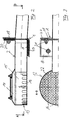
- FIG. 1 shows a right-angled angle piece 1, which is connected with a horizontal leg to a roof surface (not shown) and with a vertical leg to a surface of a wall section (not shown) that forms the roof boundary (not shown).
- a pipe section 2 is laid on the roof surface and on the horizontal leg of the angle piece 1, passes through a corresponding through opening of the vertical leg of the angle piece 1 and is passed through the width of the wall piece.
- a curved angle piece 3 is connected to the pipe section 2, which produces a transition into a vertical downpipe 4.
- the downpipe 4 has an upper drop section 5 which merges with a step-shaped narrowing 6 into a narrowing section 7, so that the falling section 5 has a larger diameter than the narrowing section 7.
- the step-shaped narrowing 6 and the narrowing section 7 are expediently part of a correspondingly shaped funnel piece, that in the area of the constriction 6 and the constriction section 7 of a continuation of the diameter of the downpipe 4 Jacket tube piece 8 is surrounded.
- a lid 9 Inspection opening 10 In the lower area of the downpipe there is a usual, lockable with a lid 9 Inspection opening 10.
- the connections of the individual sections the downpipe 4 and the connection to the elbow 3 and Pipe section 2 is sealed with known socket connections 11 manufactured.
- a free end of the pipe section 2 laid on the roof surface forms a vertical drain opening 12, which is somewhat located within a pot arrangement 13, since the pipe section 2 um led a small amount into the pot assembly 13 sealed is.
- the pot arrangement 13 is upwards, above the pipe section 2, sealed airtight by a cover 14 and has a circular cylindrical jacket wall 15 in which there are inlet openings 16 are distributed over the circumference of the jacket wall 15.
- the inlet openings 16 are vertical, open at the bottom Slits formed about halfway up the jacket wall 15 end, so that the inlet openings 16 from the Area starting only over part of the height of the jacket wall 15 extend.
- the height of the inlet openings 16 corresponds to a limit of Water level on the surface.
- Figure 2 illustrates that on both legs of the elbow 1, a sealing sheet 17, 18 is laid, which is pressed by an associated flange 19, 20 with the help of fastening screws 21 sealing against the relevant leg of the elbow 1.
- FIG. 2 also shows that the pipe section 2 is divided in the area of the angle section 1 and is continued inclined downward by a small angle within the wall section (not shown).
- FIG. 3 illustrates that the pot arrangement 13 is provided with a bottom designed as a mesh screen 22, which has the function of preventing the sealing membrane of the surface from being pulled up due to the negative pressure effect in the downpipe 4 - and thus in the pot arrangement 13.
- the second embodiment of the invention shown in FIGS. 4 to 6 differs from the first embodiment shown in FIGS. 1 to 3 only in that the pipe section 2 ′ outside the wall section, that is to say in the area of the surface, with an obliquely upward section 23 is provided so that the pipe piece 2 'is passed through the vertical leg of the leg piece 1' at a distance from the surface or from the horizontal leg of the angle piece 1 ', whereby water drainage is only possible when the distance of the passage of the pipe piece 2 'of the area corresponding minimum accumulation height is present.
- Such a drainage characteristic is used for emergency drains that only take effect when regular drainage devices are not sufficient due to blockages or excessive water to keep the surface water from rising below the minimum accumulation level.
Landscapes
- Engineering & Computer Science (AREA)
- Architecture (AREA)
- Civil Engineering (AREA)
- Structural Engineering (AREA)
- Sink And Installation For Waste Water (AREA)
- Massaging Devices (AREA)
- Seal Device For Vehicle (AREA)
- Electrical Discharge Machining, Electrochemical Machining, And Combined Machining (AREA)
- Building Environments (AREA)
- Drying Of Solid Materials (AREA)
Abstract
Description
- Figur 1
- einen Vertikalschnitt durch ein erstes Ausführungsbeispiel einer erfindungsgemäßen Ablaufvorrichtung
- Figur 2
- eine vergrößerte Darstellung des Bereichs der Ablauföffnung und des Eintritts des Rohrstücks in das Wandstück gemäß Figur 1
- Figur 3
- einen Horizontalschnitt durch die in Figur 2 dargestellte Anordnung
- Figur 4
- einen Vertikalschnitt analog Figur 1 durch eine zweite Ausführungsform der erfindungsgemäßen Ablaufvorrichtung
- Figur 5
- eine Darstellung der zweiten Ausbildungsform analog Figur 2
- Figur 6
- eine Darstellung der zweiten Ausführungsform analog Figur 3.
Claims (6)
- Ablaufvorrichtung zur Abführung von Wasser von einer im Wesentlichen ebenen Fläche, insbesondere von einem Flachdach, durch ein die Fläche begrenzendes Wandstück hindurch, mit einer durch ein sich durch das Wandstück erstreckendes Rohrstück (2, 2') gebildete Ablauföffnung (12), einer Abdeckung (13) zum Abschließen der Ablauföffnung (12) gegen Lufteintritt bei Erreichen eines Grenzwerts des Wasserstands auf der Fläche und mit einer sich an der Außenseite des Wandstücks an das Rohrstück (2, 2') anschließenden Fallleitung (4), die zur Vollfüllung beim Erreichen des Grenzwerts des Wasserstandes und zur Ausbildung eines saugenden Unterdrucks dimensioniert ist, dadurch gekennzeichnet, dass das Rohrstück (2, 2') auf der Fläche außerhalb des Wandstücks fortgesetzt ist und dass die Ablauföffnung (12) mit einem Abstand von dem Wandstück angeordnet ist, der außerhalb des Rohrstücks (2, 2') eine allseitige Anströmung der Ablauföffnung (12) ermöglicht.
- Ablaufvorrichtung nach Anspruch 1, dadurch gekennzeichnet, dass sich das Rohrstück (2, 2') in eine die Abdeckung bildende Topfanordnung erstreckt, die eine kreiszylindrische Mantelwand (15) mit sich über einen Teil der Höhe der Mantelwand (15) erstreckenden Einlauföffnungen (16) aufweist.
- Ablaufvorrichtung nach Anspruch 2, dadurch gekennzeichnet, dass die Höhe der Einlauföffnungen (16) dem Grenzwert des Wasserstandes entspricht.
- Ablaufvorrichtung nach einem der Ansprüche 1 bis 3, dadurch gekennzeichnet, dass die Fallleitung (4) über einen Fallabschnitt (5) von mehreren Metern einen großen Innendurchmesser aufweist, der am Ende des Fallabschnitts (5) stufenförmig in einen Verengungsabschnitt (7) mit einem geringeren Durchmesser übergeht.
- Ablaufvorrichtung nach Anspruch 4, dadurch gekennzeichnet, dass der Fallabschnitt (5) etwa vier Meter lang ist.
- Ablaufvorrichtung nach einem der Ansprüche 1 bis 5, dadurch gekennzeichnet, dass das Rohrstück (2') vor dem Eintritt in das Wandstück ansteigend ausgebildet ist und mit einem lichten Abstand von der Fläche in das Wandstück eintritt.
Applications Claiming Priority (2)
| Application Number | Priority Date | Filing Date | Title |
|---|---|---|---|
| DE19956024A DE19956024C2 (de) | 1999-11-22 | 1999-11-22 | Ablaufvorrichtung |
| DE19956024 | 1999-11-22 |
Publications (3)
| Publication Number | Publication Date |
|---|---|
| EP1101880A2 true EP1101880A2 (de) | 2001-05-23 |
| EP1101880A3 EP1101880A3 (de) | 2001-07-04 |
| EP1101880B1 EP1101880B1 (de) | 2002-07-31 |
Family
ID=7929839
Family Applications (1)
| Application Number | Title | Priority Date | Filing Date |
|---|---|---|---|
| EP00125571A Expired - Lifetime EP1101880B1 (de) | 1999-11-22 | 2000-11-22 | Ablaufvorrichtung |
Country Status (4)
| Country | Link |
|---|---|
| EP (1) | EP1101880B1 (de) |
| AT (1) | ATE221605T1 (de) |
| DE (2) | DE19956024C2 (de) |
| DK (1) | DK1101880T3 (de) |
Cited By (1)
| Publication number | Priority date | Publication date | Assignee | Title |
|---|---|---|---|---|
| CN104005523A (zh) * | 2014-06-13 | 2014-08-27 | 北京建筑大学 | 一种平屋顶雨水调蓄装置及调蓄方法 |
Families Citing this family (2)
| Publication number | Priority date | Publication date | Assignee | Title |
|---|---|---|---|---|
| DE102009023463B4 (de) * | 2009-06-02 | 2016-04-07 | Wolfgang Vahlbrauk | Einrichtung zur Entwässerung einer Dachfläche |
| NL2025821B1 (nl) * | 2020-06-12 | 2022-02-16 | Adrianus Henricus Maria Schoormans Johannes | Een uitstroomelement voor het in een in hoofdzaak horizontaal vlak van een dak afvoeren van hemelwater. |
Family Cites Families (7)
| Publication number | Priority date | Publication date | Assignee | Title |
|---|---|---|---|---|
| DE1983741U (de) * | 1967-12-08 | 1968-04-18 | Johan George Schmidt | Dachbauteil. |
| US3692040A (en) * | 1971-01-11 | 1972-09-19 | Drain Away Inc | Roof draining systems |
| US5063959A (en) * | 1990-07-17 | 1991-11-12 | Peterson David T | Method and apparatus for free-standing water removal from roof and siphon head therefore |
| DE9101007U1 (de) * | 1991-01-26 | 1991-04-18 | Bremer Bedachungs Betrieb GmbH, 2800 Bremen | Absaugvorrichtung |
| DE19812398C2 (de) * | 1998-03-20 | 2002-05-23 | Wolfgang Vahlbrauk | Verfahren und Vorrichtung zur Ableitung von Wasser von einer im wesentlichen ebenen Fläche |
| DE29823303U1 (de) * | 1998-12-24 | 1999-04-08 | Vahlbrauk, Wolfgang, Dipl.-Ing., 37581 Bad Gandersheim | Wasserablauf |
| DE19960128C2 (de) * | 1999-12-13 | 2002-05-08 | Wolfgang Vahlbrauk | Wasserablauf für versiegelte Flächen |
-
1999
- 1999-11-22 DE DE19956024A patent/DE19956024C2/de not_active Expired - Fee Related
-
2000
- 2000-11-22 DK DK00125571T patent/DK1101880T3/da active
- 2000-11-22 AT AT00125571T patent/ATE221605T1/de active
- 2000-11-22 DE DE50000332T patent/DE50000332D1/de not_active Expired - Lifetime
- 2000-11-22 EP EP00125571A patent/EP1101880B1/de not_active Expired - Lifetime
Cited By (1)
| Publication number | Priority date | Publication date | Assignee | Title |
|---|---|---|---|---|
| CN104005523A (zh) * | 2014-06-13 | 2014-08-27 | 北京建筑大学 | 一种平屋顶雨水调蓄装置及调蓄方法 |
Also Published As
| Publication number | Publication date |
|---|---|
| DK1101880T3 (da) | 2002-09-02 |
| ATE221605T1 (de) | 2002-08-15 |
| DE50000332D1 (de) | 2002-09-05 |
| EP1101880A3 (de) | 2001-07-04 |
| DE19956024C2 (de) | 2002-06-13 |
| EP1101880B1 (de) | 2002-07-31 |
| DE19956024A1 (de) | 2001-06-21 |
Similar Documents
| Publication | Publication Date | Title |
|---|---|---|
| EP3283353B1 (de) | Windlaufabdeckungsanordnung für ein kraftfahrzeug | |
| EP2453065A2 (de) | Ablaufgarnitur mit verdeckt positionierbarem Überlauf | |
| EP1101880B1 (de) | Ablaufvorrichtung | |
| EP1036894B1 (de) | Notablaufvorrichtung | |
| DE20100826U1 (de) | Ablauf mit Geruchsverschluss | |
| EP1108827B1 (de) | Wasserablauf für versiegelte Flächen | |
| DE4212205C2 (de) | Schwimmbad-Ablaufsystem | |
| DE102005012439A1 (de) | Wasserabführvorrichtung | |
| DE2241763A1 (de) | Einlaufgarnitur fuer spuelkaesten | |
| DE102007042527A1 (de) | Notablauf zur Entwässerung einer Fläche | |
| EP2098657B1 (de) | Dachentwässerungsvorrichtung | |
| EP0834621A2 (de) | Ablaufarmatur, insbesondere für eine Duschwanne | |
| DE2522425B2 (de) | Bodenablauf mit geruchverschluss fuer abwasserbehaelter | |
| DE19756023C2 (de) | Dachentlüftungssystem | |
| DE19836930C2 (de) | Vorrichtung zur Ableitung von Wasser von einer im wesentlichen ebenen Fläche | |
| EP1160390A2 (de) | Vorrichtung zur Dachentwässerung | |
| DE102005012438B4 (de) | Wasserabführvorrichtung | |
| DE29611847U1 (de) | Dachentwässerungsvorrichtung | |
| DE3436828C1 (de) | Falleitung für die Wasserabfuhr von Gebäudedecken | |
| DE4327317C1 (de) | Regenwassersammler | |
| EP1544371A1 (de) | Dachwassereinlauf | |
| DE2301976A1 (de) | Regenwasser-fallrohr u.dgl | |
| DE2318885A1 (de) | Dachentluefter | |
| DE20205749U1 (de) | Regenwasser-Ablaufleitung | |
| DE8705737U1 (de) | Vorrichtung zur Einleitung von Rauchgasen in das Innere eines Kühlturms |
Legal Events
| Date | Code | Title | Description |
|---|---|---|---|
| PUAI | Public reference made under article 153(3) epc to a published international application that has entered the european phase |
Free format text: ORIGINAL CODE: 0009012 |
|
| PUAL | Search report despatched |
Free format text: ORIGINAL CODE: 0009013 |
|
| AK | Designated contracting states |
Kind code of ref document: A2 Designated state(s): AT BE CH CY DE DK ES FI FR GB GR IE IT LI LU MC NL PT SE TR |
|
| AX | Request for extension of the european patent |
Free format text: AL;LT;LV;MK;RO;SI |
|
| AK | Designated contracting states |
Kind code of ref document: A3 Designated state(s): AT BE CH CY DE DK ES FI FR GB GR IE IT LI LU MC NL PT SE TR |
|
| AX | Request for extension of the european patent |
Free format text: AL;LT;LV;MK;RO;SI |
|
| 17P | Request for examination filed |
Effective date: 20010920 |
|
| GRAG | Despatch of communication of intention to grant |
Free format text: ORIGINAL CODE: EPIDOS AGRA |
|
| 17Q | First examination report despatched |
Effective date: 20020116 |
|
| AKX | Designation fees paid |
Free format text: AT BE CH CY DE DK ES FI FR GB GR IE IT LI LU MC NL PT SE TR |
|
| GRAG | Despatch of communication of intention to grant |
Free format text: ORIGINAL CODE: EPIDOS AGRA |
|
| GRAH | Despatch of communication of intention to grant a patent |
Free format text: ORIGINAL CODE: EPIDOS IGRA |
|
| GRAH | Despatch of communication of intention to grant a patent |
Free format text: ORIGINAL CODE: EPIDOS IGRA |
|
| GRAA | (expected) grant |
Free format text: ORIGINAL CODE: 0009210 |
|
| AK | Designated contracting states |
Kind code of ref document: B1 Designated state(s): AT BE CH CY DE DK ES FI FR GB GR IE IT LI LU MC NL PT SE TR |
|
| PG25 | Lapsed in a contracting state [announced via postgrant information from national office to epo] |
Ref country code: IT Free format text: LAPSE BECAUSE OF FAILURE TO SUBMIT A TRANSLATION OF THE DESCRIPTION OR TO PAY THE FEE WITHIN THE PRESCRIBED TIME-LIMIT;WARNING: LAPSES OF ITALIAN PATENTS WITH EFFECTIVE DATE BEFORE 2007 MAY HAVE OCCURRED AT ANY TIME BEFORE 2007. THE CORRECT EFFECTIVE DATE MAY BE DIFFERENT FROM THE ONE RECORDED. Effective date: 20020731 Ref country code: GR Free format text: LAPSE BECAUSE OF FAILURE TO SUBMIT A TRANSLATION OF THE DESCRIPTION OR TO PAY THE FEE WITHIN THE PRESCRIBED TIME-LIMIT Effective date: 20020731 Ref country code: TR Free format text: LAPSE BECAUSE OF FAILURE TO SUBMIT A TRANSLATION OF THE DESCRIPTION OR TO PAY THE FEE WITHIN THE PRESCRIBED TIME-LIMIT Effective date: 20020731 Ref country code: IE Free format text: LAPSE BECAUSE OF FAILURE TO SUBMIT A TRANSLATION OF THE DESCRIPTION OR TO PAY THE FEE WITHIN THE PRESCRIBED TIME-LIMIT Effective date: 20020731 |
|
| REF | Corresponds to: |
Ref document number: 221605 Country of ref document: AT Date of ref document: 20020815 Kind code of ref document: T |
|
| REG | Reference to a national code |
Ref country code: CH Ref legal event code: EP Ref country code: GB Ref legal event code: FG4D Free format text: NOT ENGLISH |
|
| REG | Reference to a national code |
Ref country code: DK Ref legal event code: T3 |
|
| REG | Reference to a national code |
Ref country code: IE Ref legal event code: FG4D Free format text: GERMAN |
|
| REF | Corresponds to: |
Ref document number: 50000332 Country of ref document: DE Date of ref document: 20020905 |
|
| GBT | Gb: translation of ep patent filed (gb section 77(6)(a)/1977) |
Effective date: 20020919 |
|
| PG25 | Lapsed in a contracting state [announced via postgrant information from national office to epo] |
Ref country code: SE Free format text: LAPSE BECAUSE OF FAILURE TO SUBMIT A TRANSLATION OF THE DESCRIPTION OR TO PAY THE FEE WITHIN THE PRESCRIBED TIME-LIMIT Effective date: 20021031 |
|
| PG25 | Lapsed in a contracting state [announced via postgrant information from national office to epo] |
Ref country code: PT Free format text: LAPSE BECAUSE OF FAILURE TO SUBMIT A TRANSLATION OF THE DESCRIPTION OR TO PAY THE FEE WITHIN THE PRESCRIBED TIME-LIMIT Effective date: 20021118 |
|
| PG25 | Lapsed in a contracting state [announced via postgrant information from national office to epo] |
Ref country code: LU Free format text: LAPSE BECAUSE OF NON-PAYMENT OF DUE FEES Effective date: 20021122 |
|
| PG25 | Lapsed in a contracting state [announced via postgrant information from national office to epo] |
Ref country code: BE Free format text: LAPSE BECAUSE OF NON-PAYMENT OF DUE FEES Effective date: 20021130 Ref country code: CY Free format text: LAPSE BECAUSE OF FAILURE TO SUBMIT A TRANSLATION OF THE DESCRIPTION OR TO PAY THE FEE WITHIN THE PRESCRIBED TIME-LIMIT Effective date: 20021130 |
|
| PG25 | Lapsed in a contracting state [announced via postgrant information from national office to epo] |
Ref country code: ES Free format text: LAPSE BECAUSE OF FAILURE TO SUBMIT A TRANSLATION OF THE DESCRIPTION OR TO PAY THE FEE WITHIN THE PRESCRIBED TIME-LIMIT Effective date: 20030130 |
|
| ET | Fr: translation filed | ||
| REG | Reference to a national code |
Ref country code: IE Ref legal event code: FD4D Ref document number: 1101880E Country of ref document: IE |
|
| BERE | Be: lapsed |
Owner name: *VAHLBRAUK WOLFGANG Effective date: 20021130 |
|
| PG25 | Lapsed in a contracting state [announced via postgrant information from national office to epo] |
Ref country code: MC Free format text: LAPSE BECAUSE OF NON-PAYMENT OF DUE FEES Effective date: 20030601 |
|
| PLBE | No opposition filed within time limit |
Free format text: ORIGINAL CODE: 0009261 |
|
| STAA | Information on the status of an ep patent application or granted ep patent |
Free format text: STATUS: NO OPPOSITION FILED WITHIN TIME LIMIT |
|
| 26N | No opposition filed |
Effective date: 20030506 |
|
| PG25 | Lapsed in a contracting state [announced via postgrant information from national office to epo] |
Ref country code: LI Free format text: LAPSE BECAUSE OF NON-PAYMENT OF DUE FEES Effective date: 20041130 |
|
| REG | Reference to a national code |
Ref country code: CH Ref legal event code: PL |
|
| REG | Reference to a national code |
Ref country code: CH Ref legal event code: AEN Free format text: DAS PATENT IST AUFGRUND DES WEITERBEHANDLUNGSANTRAGS VOM 19.08.2005 REAKTIVIERT WORDEN. |
|
| REG | Reference to a national code |
Ref country code: CH Ref legal event code: NV Representative=s name: BRAUNPAT BRAUN EDER AG |
|
| REG | Reference to a national code |
Ref country code: DE Ref legal event code: R082 Ref document number: 50000332 Country of ref document: DE Representative=s name: GRAMM, LINS & PARTNER PATENT- UND RECHTSANWAEL, DE |
|
| REG | Reference to a national code |
Ref country code: FR Ref legal event code: PLFP Year of fee payment: 16 |
|
| REG | Reference to a national code |
Ref country code: FR Ref legal event code: PLFP Year of fee payment: 17 |
|
| PGFP | Annual fee paid to national office [announced via postgrant information from national office to epo] |
Ref country code: DK Payment date: 20161124 Year of fee payment: 17 Ref country code: FI Payment date: 20161123 Year of fee payment: 17 Ref country code: FR Payment date: 20161124 Year of fee payment: 17 Ref country code: NL Payment date: 20161124 Year of fee payment: 17 Ref country code: GB Payment date: 20161124 Year of fee payment: 17 Ref country code: CH Payment date: 20161124 Year of fee payment: 17 |
|
| PGFP | Annual fee paid to national office [announced via postgrant information from national office to epo] |
Ref country code: AT Payment date: 20161122 Year of fee payment: 17 |
|
| REG | Reference to a national code |
Ref country code: CH Ref legal event code: PCAR Free format text: NEW ADDRESS: HOLEESTRASSE 87, 4054 BASEL (CH) |
|
| REG | Reference to a national code |
Ref country code: DK Ref legal event code: EBP Effective date: 20171130 |
|
| REG | Reference to a national code |
Ref country code: NL Ref legal event code: MM Effective date: 20171201 |
|
| REG | Reference to a national code |
Ref country code: AT Ref legal event code: MM01 Ref document number: 221605 Country of ref document: AT Kind code of ref document: T Effective date: 20171122 |
|
| GBPC | Gb: european patent ceased through non-payment of renewal fee |
Effective date: 20171122 |
|
| PG25 | Lapsed in a contracting state [announced via postgrant information from national office to epo] |
Ref country code: CH Free format text: LAPSE BECAUSE OF NON-PAYMENT OF DUE FEES Effective date: 20171130 Ref country code: FI Free format text: LAPSE BECAUSE OF NON-PAYMENT OF DUE FEES Effective date: 20171122 Ref country code: LI Free format text: LAPSE BECAUSE OF NON-PAYMENT OF DUE FEES Effective date: 20171130 |
|
| PG25 | Lapsed in a contracting state [announced via postgrant information from national office to epo] |
Ref country code: AT Free format text: LAPSE BECAUSE OF NON-PAYMENT OF DUE FEES Effective date: 20171122 |
|
| REG | Reference to a national code |
Ref country code: FR Ref legal event code: ST Effective date: 20180731 |
|
| PG25 | Lapsed in a contracting state [announced via postgrant information from national office to epo] |
Ref country code: FR Free format text: LAPSE BECAUSE OF NON-PAYMENT OF DUE FEES Effective date: 20171130 Ref country code: NL Free format text: LAPSE BECAUSE OF NON-PAYMENT OF DUE FEES Effective date: 20171201 |
|
| PG25 | Lapsed in a contracting state [announced via postgrant information from national office to epo] |
Ref country code: GB Free format text: LAPSE BECAUSE OF NON-PAYMENT OF DUE FEES Effective date: 20171122 Ref country code: DK Free format text: LAPSE BECAUSE OF NON-PAYMENT OF DUE FEES Effective date: 20171130 |
|
| PGFP | Annual fee paid to national office [announced via postgrant information from national office to epo] |
Ref country code: DE Payment date: 20191127 Year of fee payment: 20 |
|
| REG | Reference to a national code |
Ref country code: DE Ref legal event code: R071 Ref document number: 50000332 Country of ref document: DE |