EP1101905A1 - Moteur à combustion avec un dispositif de lubrification pour diminuer l' usure entre une courroie de distribution et une poulie tendeuse - Google Patents
Moteur à combustion avec un dispositif de lubrification pour diminuer l' usure entre une courroie de distribution et une poulie tendeuse Download PDFInfo
- Publication number
- EP1101905A1 EP1101905A1 EP99309079A EP99309079A EP1101905A1 EP 1101905 A1 EP1101905 A1 EP 1101905A1 EP 99309079 A EP99309079 A EP 99309079A EP 99309079 A EP99309079 A EP 99309079A EP 1101905 A1 EP1101905 A1 EP 1101905A1
- Authority
- EP
- European Patent Office
- Prior art keywords
- oil
- engine
- timing chain
- cylinder body
- tension pulley
- Prior art date
- Legal status (The legal status is an assumption and is not a legal conclusion. Google has not performed a legal analysis and makes no representation as to the accuracy of the status listed.)
- Withdrawn
Links
- 230000001050 lubricating effect Effects 0.000 title description 4
- 239000003921 oil Substances 0.000 claims abstract description 82
- 239000010687 lubricating oil Substances 0.000 claims abstract description 13
- 238000010276 construction Methods 0.000 description 4
Images






Classifications
-
- F—MECHANICAL ENGINEERING; LIGHTING; HEATING; WEAPONS; BLASTING
- F01—MACHINES OR ENGINES IN GENERAL; ENGINE PLANTS IN GENERAL; STEAM ENGINES
- F01M—LUBRICATING OF MACHINES OR ENGINES IN GENERAL; LUBRICATING INTERNAL COMBUSTION ENGINES; CRANKCASE VENTILATING
- F01M11/00—Component parts, details or accessories, not provided for in, or of interest apart from, groups F01M1/00 - F01M9/00
- F01M11/02—Arrangements of lubricant conduits
-
- F—MECHANICAL ENGINEERING; LIGHTING; HEATING; WEAPONS; BLASTING
- F01—MACHINES OR ENGINES IN GENERAL; ENGINE PLANTS IN GENERAL; STEAM ENGINES
- F01M—LUBRICATING OF MACHINES OR ENGINES IN GENERAL; LUBRICATING INTERNAL COMBUSTION ENGINES; CRANKCASE VENTILATING
- F01M9/00—Lubrication means having pertinent characteristics not provided for in, or of interest apart from, groups F01M1/00 - F01M7/00
- F01M9/10—Lubrication of valve gear or auxiliaries
- F01M9/108—Lubrication of valve gear or auxiliaries of auxiliaries
Definitions
- This invention relates to an engine that includes a timing chain and a tension pulley, more particularly to an engine, which is provided with a lubricating device for reducing wear between the timing chain and the tension pulley.
- a conventional motorcycle engine 1 is shown to include a cylinder body 11, a crankcase 12 that is connected fixedly to the lower end of the cylinder body 11, and a cylinder head 13 that is connected fixedly to the upper end of the cylinder body 11.
- the crankcase 12 includes a left housing 121, a right housing 122, a left housing cover 123, a right housing cover 124, and a crankshaft 125, on which alower sprocket wheel 246 is sleeved fixedly.
- a camshaft 131 is journalled within the cylinder head 13, and has an oil inlet passage 134 and a plurality of oil outlets 132.
- An upper sprocket wheel 133 is sleeved fixedly on the camshaft 131.
- a timing chain 14 engages the upper and lower sprocket wheels 133, 126, and is tautened by a tension pulley 127, which is disposed in the cylinder body 11.
- An oil passage 15 (shown by the dotted lines) has an upper portion that is communicated with the oil inlet passage 134 in the camshaft 131, and a lower portion that is formed in the crankcase 12. Lubricating oil in the crankcase 12 is forced by an oil pump (not shown) to the oil passage 15, and is then sprayed from the oil outlets 132 in the camshaft 131, thereby lubricating the parts under the camshaft 131.
- a part of the lubricating oil in the crankcase 12 is carried by the timing chain 14 to move onto the upper sprocket wheel 133 and the tension pulley 127 when the timing chain 14 circulates.
- the timing chain 14, the upper sprocket wheel 133 and the tension pulley 127 can be lubricated.
- the horsepower number of the engine 1 is up to about 7.4, however, it is difficult to move the lubricating oil from the timing chain 14 to the upper sprocket wheel 133 and the tension pulley 127. In this case, serious wear occurs between the timing chain 14 and the tension pulley 127.
- the object of this invention is to provide an engine, which is provided with a lubricating device for reducing wear between a timing chain and a tension pulley.
- an engine includes a cylinder body, and a crankcase connected fixedly to the lower end of the cylinder body and including a crankshaft that is journalled within the crankcase, a lower sprocket wheel that is sleeved fixedly on the crankshaft, and an oil pump that is disposed in the crankcase.
- a cylinder head is connected fixedly to the upper end of the cylinder body, and includes a camshaft that is journalled therein, and an upper sprocket wheel that is sleeved fixedly on the camshaft.
- An oil passage is formed through the cylinder body, and has an upper portion that is formed in the cylinder head, and a lower portion that is formed in the crankcase.
- Lubricating oil is forced by the oil pump to flow through the oil passage.
- a timing chain engages the upper and lower sprocket wheels for transferring rotation between the camshaft and the crankshaft.
- An adjustable tension pulley is disposed in the cylinder body for maintaining the timing chain in a tautened condition.
- An oil slot unit is formed in the engine, and has an oil inlet that is communicated with the oil passage, and an oil outlet that is directed to at least one of the timing chain and the tension pulley so that the lubricating oil is sprayed from the oil slot unit onto the at least one of the timing chain and the tension pulley, thereby reducing wear between the timing chain and the tension pulley.
- a first preferred embodiment of a motorcycle engine according to this invention is shown to include a cylinder 21, a crankcase 22, a cylinder head 23, a timing chain 24, an adjustable tension pulley 25, an oil passage 26, and an oil slot unit that consists of a single slot 27.
- the crankcase 22 is connected fixedly to the lower end of the cylinder 21, and includes a left housing 221, a right housing 222, a left housing cover 223, a right housing cover 224, an oil pump 225 (see Fig. 3), a crankshaft 226, and a lower sprocket wheel 227.
- the oil pump 225 is disposed in the crankcase 22.
- the crankshaft 226 is journalled in the crankcase 22.
- the lower sprocket wheel 227 is sleeved fixedly on the crankshaft 226.
- the cylinder head 23 is connected fixedly to the upper end of the cylinder body 21, and includes a camshaft 231 that is journalled therein, and an upper sprocket wheel 233 that is sleeved fixedly on the camshaft 231.
- the timing chain 24 engages the upper and lower sprocket wheels 233, 227 for transferring rotation between the camshaft 231 and the crankshaft 226.
- the tension pulley 25 is disposed in the cylinder body 21 for maintaining the timing chain 24 in a tautened condition.
- the oil passage 26 is formed through the cylinder body 21, and has an upper end portion that is formed in the cylinder head 23, and a lower end portion that is formed in the crankcase 22. Lubricating oil is forced by the oil pump 225 to flow through the oil passage 26.
- the oil slot 27 is horizontal, and is located between the camshaft 231 and the crankshaft 226.
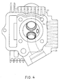
- Fig. 4 is a top view of the cylinder head 23.
- the oil slot 27 is formed in a horizontal bottom surface of the cylinder head 23, which abuts against a horizontal top surface of the cylinder body 21 (see Fig. 2) .
- the slot 27 has an oil inlet that is located at the right end thereof and that is communicated with the oil passage 26, and an oil outlet, which is located at the left end of the slot 27 and which is directed to a portion of the timing chain 14 that is located over the tension pulley 25.
- Fig. 5 illustrates a second preferred embodiment of this invention, which is similar to the first embodiment in construction except for the position of the oil slot unit in the engine.
- the oil slot unit consists of a single horizontal slot 37.
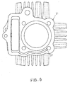
- Fig. 6 is a top view of a cylinder body 31 of the second embodiment, in which the slot 37 is formed in a horizontal top surface of the cylinder body 31.
- the slot 37 has a right end that constitutes an oil inlet, and a left end, which constitutes an oil outlet that is directed to a portion of a timing chain 34 (see Fig. 5) immediately over a tension pulley 35 (see Fig. 5) .
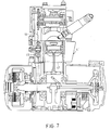
- Fig. 7 illustrates a third preferred embodiment of this invention, which is similar to the first embodiment in construction except for the position of the oil slot unit in the engine.
- the oil slot unit consists of a single horizontal slot 47.
- Fig. 8 is a bottom view of a cylinder body 41 of the third embodiment, in which the slot 47 is formed in a horizontal bottom surface of the cylinder body 41.
- the slot 47 has a right end that constitutes an oil inlet, and a left end, which constitutes an oil outlet that is directed to a portion of a timing chain 44 (see Fig. 7) under a tension pulley 45 (see Fig. 7).
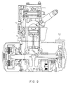
- Fig. 9 illustrates a fourth preferred embodiment of this invention, which is similar to the first embodiment in construction except for the position of the oil slot unit in the engine.
- the oil slot unit consists of a single horizontal slot 57.
- Fig. 10 is a top view of a crankcase 52 of the fourth embodiment, in which the slot 57 is formed in a horizontal top surface of the crankcase 52.
- the slot 57 has a right end that constitutes an oil inlet, and a left end, which constitutes an oil outlet that is directed to a portion of a timing chain 54 (see Fig. 9) under a tension pulley 55 (see Fig. 9).
- Figs. 11 illustrates a fifth preferred embodiment of this invention, which is similar to the first embodiment in construction except for the oil slot unit in the engine.
- the oil slot unit 67 consists of two intersecting slots 611, 612.
- Figs. 12 and 13 show a cylinder body 61 of the fourth embodiment, in which the slots 611, 612 are formed in the cylinder body 61.
- the right ends of the slots 611, 612 are closed by two plugs 613, 614, respectively.
- the left end of the slot 611 is opened, and constitutes an oil inlet.
- the left end of the slot 612 is opened, and constitutes an oil outlet that is directed to a tension pulley 65 (see Fig. 11).
- a part of the lubricating oil in the crankcase is carried by the timing chain onto the tension pulley.
- another part of the lubricating oil in the crankcase is sprayed from the oil outlet of the oil slot unit onto the timing chain and the tension pulley, thereby reducing wear between the timing chain and the tension pulley.
- An engine has an oil slot unit with an oil inlet that is communicated with an oil passage, and an oil outlet that is directed to at least one of a timing chain and a tension pulley.
- Lubricating oil is pumped to flow from a crankcase to the oil slot unit via the oil passage, and is sprayed from the oil outlet of the oil slot unit onto the at least one of the timing chain and the tension pulley. Accordingly, wear between the timing chain and the tension pulley is reduced.
Landscapes
- Engineering & Computer Science (AREA)
- Mechanical Engineering (AREA)
- General Engineering & Computer Science (AREA)
- Lubrication Of Internal Combustion Engines (AREA)
- Devices For Conveying Motion By Means Of Endless Flexible Members (AREA)
Priority Applications (1)
| Application Number | Priority Date | Filing Date | Title |
|---|---|---|---|
| EP99309079A EP1101905A1 (fr) | 1999-11-16 | 1999-11-16 | Moteur à combustion avec un dispositif de lubrification pour diminuer l' usure entre une courroie de distribution et une poulie tendeuse |
Applications Claiming Priority (1)
| Application Number | Priority Date | Filing Date | Title |
|---|---|---|---|
| EP99309079A EP1101905A1 (fr) | 1999-11-16 | 1999-11-16 | Moteur à combustion avec un dispositif de lubrification pour diminuer l' usure entre une courroie de distribution et une poulie tendeuse |
Publications (1)
| Publication Number | Publication Date |
|---|---|
| EP1101905A1 true EP1101905A1 (fr) | 2001-05-23 |
Family
ID=8241734
Family Applications (1)
| Application Number | Title | Priority Date | Filing Date |
|---|---|---|---|
| EP99309079A Withdrawn EP1101905A1 (fr) | 1999-11-16 | 1999-11-16 | Moteur à combustion avec un dispositif de lubrification pour diminuer l' usure entre une courroie de distribution et une poulie tendeuse |
Country Status (1)
| Country | Link |
|---|---|
| EP (1) | EP1101905A1 (fr) |
Citations (4)
| Publication number | Priority date | Publication date | Assignee | Title |
|---|---|---|---|---|
| US4974561A (en) * | 1988-11-16 | 1990-12-04 | Nissan Motor Co., Ltd. | Lubrication device for engine |
| DE4037188A1 (de) * | 1990-11-22 | 1992-05-27 | Audi Ag | Schmiersystem fuer die nockenwellenlager einer brennkraftmaschine |
| US5309878A (en) * | 1993-03-22 | 1994-05-10 | Tecumseh Products Company | Pulsed pressure lubrication system for an overhead valve engine |
| DE19729971C1 (de) * | 1997-07-12 | 1998-10-08 | Porsche Ag | Brennkraftmaschine |
-
1999
- 1999-11-16 EP EP99309079A patent/EP1101905A1/fr not_active Withdrawn
Patent Citations (4)
| Publication number | Priority date | Publication date | Assignee | Title |
|---|---|---|---|---|
| US4974561A (en) * | 1988-11-16 | 1990-12-04 | Nissan Motor Co., Ltd. | Lubrication device for engine |
| DE4037188A1 (de) * | 1990-11-22 | 1992-05-27 | Audi Ag | Schmiersystem fuer die nockenwellenlager einer brennkraftmaschine |
| US5309878A (en) * | 1993-03-22 | 1994-05-10 | Tecumseh Products Company | Pulsed pressure lubrication system for an overhead valve engine |
| DE19729971C1 (de) * | 1997-07-12 | 1998-10-08 | Porsche Ag | Brennkraftmaschine |
Similar Documents
| Publication | Publication Date | Title |
|---|---|---|
| US6047667A (en) | Motorcycle camshaft support plate | |
| DE10247047B4 (de) | Wassergekühlter V-Motor für ein Motorrad | |
| US5743230A (en) | Balancer shaft supporting structure in engine | |
| CA1237956A (fr) | Mecanisme de lubrification dans un moteur a combustion interne | |
| US5788381A (en) | Rotary shaft lubricating structure | |
| CA2376562A1 (fr) | Systeme de lubrification pour moteur de motoneige | |
| US20020007812A1 (en) | Structure for lubricating valve-operating device of OHC engine and cover member for OHC engine | |
| US9540973B2 (en) | Oil passage structure of dry sump engine and oil passage structure of V-shaped dry sump engine | |
| DE60219379T2 (de) | Lagerungsgehäuse für eine Brennkraftmaschine | |
| DE102018204651A1 (de) | Laufwerkstruktur eines Verbrennungsmotors | |
| JP2530930Y2 (ja) | 駆動伝達装置 | |
| HU221284B1 (en) | Chain pulley cover for the oil pump of an internal combustion engine | |
| US20020007983A1 (en) | Lubricating system for OHC engine | |
| ZA927879B (en) | Internal combustion engine with oil pump mounted on the camshaft. | |
| JP2004116510A (ja) | V型エンジン用タイミングチェーンの潤滑装置 | |
| US6260536B1 (en) | Intake passage device for an internal combustion engine | |
| EP1101905A1 (fr) | Moteur à combustion avec un dispositif de lubrification pour diminuer l' usure entre une courroie de distribution et une poulie tendeuse | |
| DE60018122T2 (de) | Brennkraftmaschine mit einer doppelten von aussen angetriebenen obenliegenden Nockenwelle | |
| US20040226528A1 (en) | Lubricating structure of OHC internal combustion engine | |
| JPH09273408A (ja) | 内燃機関のチェーン潤滑装置 | |
| EP1063397A3 (fr) | Carter de pompe pour un moteur à combustion interne | |
| DE19956818A1 (de) | Kühleinrichtung für einen Motor | |
| JPH0533682Y2 (fr) | ||
| DE60113196T2 (de) | Viertaktbrennkraftmaschine | |
| EP3321477B1 (fr) | Motocyclette |
Legal Events
| Date | Code | Title | Description |
|---|---|---|---|
| PUAI | Public reference made under article 153(3) epc to a published international application that has entered the european phase |
Free format text: ORIGINAL CODE: 0009012 |
|
| AK | Designated contracting states |
Kind code of ref document: A1 Designated state(s): AT BE CH CY DE DK ES FI FR GB GR IE IT LI LU MC NL PT SE |
|
| AX | Request for extension of the european patent |
Free format text: AL;LT;LV;MK;RO;SI |
|
| 17P | Request for examination filed |
Effective date: 20010611 |
|
| STAA | Information on the status of an ep patent application or granted ep patent |
Free format text: STATUS: THE APPLICATION HAS BEEN WITHDRAWN |
|
| 18W | Application withdrawn |
Withdrawal date: 20011112 |