EP1101948A2 - Kühlwasserpumpe, insbesondere für eine Brennkraftmaschine - Google Patents
Kühlwasserpumpe, insbesondere für eine Brennkraftmaschine Download PDFInfo
- Publication number
- EP1101948A2 EP1101948A2 EP00890333A EP00890333A EP1101948A2 EP 1101948 A2 EP1101948 A2 EP 1101948A2 EP 00890333 A EP00890333 A EP 00890333A EP 00890333 A EP00890333 A EP 00890333A EP 1101948 A2 EP1101948 A2 EP 1101948A2
- Authority
- EP
- European Patent Office
- Prior art keywords
- leakage
- cooling water
- water pump
- space
- housing
- Prior art date
- Legal status (The legal status is an assumption and is not a legal conclusion. Google has not performed a legal analysis and makes no representation as to the accuracy of the status listed.)
- Granted
Links
- 239000002826 coolant Substances 0.000 title claims abstract description 18
- 238000002485 combustion reaction Methods 0.000 title claims description 4
- XLYOFNOQVPJJNP-UHFFFAOYSA-N water Substances O XLYOFNOQVPJJNP-UHFFFAOYSA-N 0.000 title description 5
- 238000007789 sealing Methods 0.000 claims abstract description 15
- 238000005266 casting Methods 0.000 claims abstract description 3
- 239000000498 cooling water Substances 0.000 claims description 29
- 238000004519 manufacturing process Methods 0.000 description 4
- 238000009434 installation Methods 0.000 description 3
- 238000004512 die casting Methods 0.000 description 2
- 238000009825 accumulation Methods 0.000 description 1
- 230000005574 cross-species transmission Effects 0.000 description 1
- 230000007547 defect Effects 0.000 description 1
- 238000001704 evaporation Methods 0.000 description 1
- 230000008020 evaporation Effects 0.000 description 1
- 239000011888 foil Substances 0.000 description 1
- 239000003292 glue Substances 0.000 description 1
- 239000002184 metal Substances 0.000 description 1
Images


Classifications
-
- F—MECHANICAL ENGINEERING; LIGHTING; HEATING; WEAPONS; BLASTING
- F04—POSITIVE - DISPLACEMENT MACHINES FOR LIQUIDS; PUMPS FOR LIQUIDS OR ELASTIC FLUIDS
- F04D—NON-POSITIVE-DISPLACEMENT PUMPS
- F04D29/00—Details, component parts, or accessories
- F04D29/40—Casings; Connections of working fluid
- F04D29/42—Casings; Connections of working fluid for radial or helico-centrifugal pumps
- F04D29/426—Casings; Connections of working fluid for radial or helico-centrifugal pumps especially adapted for liquid pumps
-
- F—MECHANICAL ENGINEERING; LIGHTING; HEATING; WEAPONS; BLASTING
- F04—POSITIVE - DISPLACEMENT MACHINES FOR LIQUIDS; PUMPS FOR LIQUIDS OR ELASTIC FLUIDS
- F04D—NON-POSITIVE-DISPLACEMENT PUMPS
- F04D29/00—Details, component parts, or accessories
- F04D29/08—Sealings
- F04D29/10—Shaft sealings
- F04D29/12—Shaft sealings using sealing-rings
- F04D29/126—Shaft sealings using sealing-rings especially adapted for liquid pumps
-
- F—MECHANICAL ENGINEERING; LIGHTING; HEATING; WEAPONS; BLASTING
- F05—INDEXING SCHEMES RELATING TO ENGINES OR PUMPS IN VARIOUS SUBCLASSES OF CLASSES F01-F04
- F05D—INDEXING SCHEME FOR ASPECTS RELATING TO NON-POSITIVE-DISPLACEMENT MACHINES OR ENGINES, GAS-TURBINES OR JET-PROPULSION PLANTS
- F05D2260/00—Function
- F05D2260/60—Fluid transfer
- F05D2260/602—Drainage
- F05D2260/6022—Drainage of leakage having past a seal
Definitions
- the invention relates to a cooling water pump, in particular for an internal combustion engine, with a housing that has at least one bearing for mounting a pump shaft has, with a sealing element for sealing the bearing opposite a working space containing the cooling medium, as well as one in the housing arranged leakage space for receiving coolant through the Sealing element has passed through.
- Cooling water pumps are relatively difficult working conditions in motor vehicles exposed. There are long downtimes and large temperature fluctuations to cope with, and it becomes maintenance-free operation over one provided a long period. It has turned out to be almost impossible in practice proven to achieve a completely leak-free seal of the pump, that means it always has to leak small amounts of cooling medium be counted. However, it is undesirable to easily leak this amount to leave the pump, as this gives the impression of a defect is awakened.
- a cooling water pump which one in the direction of the pump shaft axis has demoldable leakage space, which is in the installation position below the pump shaft.
- the leakage space has an opening to the outside, which are at least partially closed by a cover, for example a metal foil is. Only a small opening remains through which the water vapor can escape or through which in the event of failure of the mechanical seal the escaping Cooling water can overflow. Since the leak chamber must be tight, it is necessary to glue the lid and additionally caulk it. Around the leakage chamber with the space between the bearing and the mechanical seal to connect, an additional connection hole is necessary. The The production of this leakage space is therefore very complex and cost-intensive.
- the publication DE 28 46 950 B1 describes a coolant pump for a liquid-cooled internal combustion engine, with a leakage chamber in the pump housing for receiving coolant that has passed through the sealing element.
- the leakage chamber designed as an evaporation chamber is drilled Blind hole executed, which is covered by a plug. For Making the leakage chamber requires additional steps, what increases the manufacturing effort.
- the leakage space in one casting process can be produced together with the housing, the leakage space through one essentially transversely, preferably in a normal plane to the pump shaft axis pulled slide is demoldable.
- the pump shaft pullable slide can preferably on the suction side arranged leakage space produced in one operation with the housing become.
- the slider is also shaped so that it is the connecting channel between the leakage space and a connection space between the bearing and Manufactures mechanical seal.
- the opening - in the installed position of the cooling water pump considered - arranged at the highest point of the leakage space is, wherein the opening is preferably surrounded by a flange surface.
- the Installation position of the leakage space is directed essentially obliquely upwards, so that no cooling water can escape through the leakage space.
- the Water vapor can escape unhindered through the opening.
- the leakage space is drawn as high as possible, the opening preferably is at least partially above the pump shaft axis. To everyone To avoid steam accumulation, it is advantageous if the cross section of the leakage space extended towards the opening.
- an leakage hole leading outwards emerges from the leakage chamber. Due to the leakage hole, the bearing will fail if the mechanical seal fails overflowing cooling water protected.
- the leakage hole is there preferably below the center of the bearing, so that overflowing cooling water can drain out of the leakage chamber through the leakage hole.
- a special one simple manufacture is possible if the leakage hole is parallel to the Pump shaft axis is arranged. The leakage hole can thus be in the opening direction of the die casting tool for the housing.
- the leakage space produced according to the invention can be used both in cooling water pumps be provided in which the suction chamber of the cooling water pump and the bearing on the same side, as well as with cooling water pumps where suction chamber and bearing are on different sides of the impeller.
- the cooling water pump shown in Fig. 1 has a housing 2 in which a bearing 3 formed by roller bearings is arranged, which has a pump shaft 4 rotatably.
- An impeller 5 is known in the pump shaft 4 Way attached.
- the impeller 5 sucks cooling medium, such as cooling water, in one Suction area 6, and pushes it in the radial direction into one in the housing 2 trained pump chamber 7.
- the pump chamber 7 is not one shown cover, as it is attached to the housing 2, closed.
- a sealing element 8 for sealing of the cooling medium is provided, this sealing element 8 for example is designed as a mechanical seal. Through this sealing element 8 prevents cooling medium from the pump chamber 7 to the bearing 3 and on can get outside.
- a connecting space 9 is arranged, one of which is directed downwards Connection channel 10 goes out and in a likewise in the housing 2 on the suction side arranged leakage space 11 opens.
- the leakage space 11 has on it - viewed in the installation position of water pump 1 - highest opening 12, which is surrounded by a flange surface 13.
- the leakage space 11 is in the Housing 2 arranged so that its walls 14 in the installed position of the water pump 1 both to a horizontal plane 15 and to a vertical axis 16 are inclined.
- the leakage space 11 can be produced by a lateral slide which is transverse to the Pump shaft axis 4a, preferably radial or tangential to pump shaft 4, thus preferably essentially in a normal plane 20 to the pump shaft axis 4a is pulled.
- the connecting channel 10 is also suitable through the shaped slider malleable. This facilitates the creation of the leakage space 11 essential.
- a predetermined amount of cooling medium can be collected in the leakage space 11 become.
- the cooling medium collected in the leakage space 11 can be heated evaporate through the bearing heat through the opening 12.
- To the steam outlet To facilitate, the leakage space 11 is shaped so that the walls 14 in Expand towards the opening 12.
- the opening 12 In order to spill over of the trapped while the vehicle is traveling To prevent cooling medium from the opening 12, the leakage space 11 is possible pulled up, the opening 12 preferably at least partially above the level of the pump shaft axis 4a - viewed in a normal plane 20 is located on the pump shaft axis 4a.
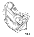
- the housing 2 To the camp 3 before overflowing, the housing 2 has one in the direction of the pump shaft axis 4a formed leakage hole 17, which from the leakage space 11th leads to the outside.
- the leakage hole 17 is preferably located below a horizontal plane 15a running through the bearing center 3a. Through this Leakage hole 17, the coolant can drain to the outside.
- the leakage hole 17 can together with the housing 2 by the die casting tool for the housing 2 are manufactured.
- the suction area 7 of the cooling water pump is located 1 on the same side of the impeller 5 as the bearing 3 and the sealing element 8.
- the leakage space 11 shaped according to the invention can of course, however also be provided in cooling water pumps 2, in which the suction area 6 and the sealing element 8 are located on different sides of the impeller 5.
- the present invention makes it possible to manufacture a cooling water pump 1 to reduce significantly.
Landscapes
- Engineering & Computer Science (AREA)
- Mechanical Engineering (AREA)
- General Engineering & Computer Science (AREA)
- Structures Of Non-Positive Displacement Pumps (AREA)
- Jet Pumps And Other Pumps (AREA)
- Fuel-Injection Apparatus (AREA)
Abstract
Description
- Fig. 1
- einen Schnitt durch eine erfindungsgemäße Kühlwasserpumpe,
- Fig. 2
- das Gehäuse der Kühlwasserpumpe in einer antriebsstirnseitigen Ansicht,
- Fig. 3
- das Gehäuse in einem Schnitt gemäß der Linie III - III in Fig. 2,
- Fig. 4
- das Gehäuse in einem Schnitt gemäß der Linie IV - IV in Fig. 3 und
- Fig. 5
- das Gehäuse in einem Schnitt gemäß der Linie V - V in Fig. 3.
Claims (7)
- Kühlwasserpumpe (1), insbesondere für eine Brennkraftmaschine, mit einem Gehäuse (2), das zumindest ein Lager (3) zur Lagerung einer Pumpenwelle (4) aufweist, mit einem Dichtelement (8) zur Abdichtung des Lagers (3) gegenüber einem das Kühlmedium enthaltenden Arbeitsraum, sowie mit einem im Gehäuse angeordneten Leckageraum zur Aufnahme von Kühlmedium, das durch das Dichtelement (8) hindurchgetreten ist, dadurch gekennzeichnet , dass der Leckageraum (11) in einem Gießvorgang zusammen mit dem Gehäuse herstellbar ist, wobei der Leckageraum (11) durch einen im wesentlichen quer, vorzugsweise in einer Normalebene (20) auf die Pumpenwellenachse (4a) gezogenen Schieber entformbar ist.
- Kühlwasserpumpe (1) nach Anspruch 1, wobei der Leckageraum (11) eine Öffnung (12) nach außen aufweist, dadurch gekennzeichnet, dass die Öffnung (12) - in der Einbaulage der Kühlwasserpumpe (1) betrachtet - an der höchsten Stelle des Leckageraumes (11) angeordnet ist, wobei vorzugsweise die Öffnung (12) von einer Flanschfläche (13) umgeben ist.
- Kühlwasserpumpe (1) nach Anspruch 1 oder 2, dadurch gekennzeichnet, dass von der Leckagekammer (11) eine nach außen führende Leckagebohrung (17) ausgeht.
- Kühlwasserpumpe (1) nach Anspruch 3, dadurch gekennzeichnet, dass die Leckagebohrung (17) - in der Einbaulage der Kühlwasserpumpe (1) betrachtet - tiefer als der Mittelpunkt (3a) des Lagers (3) angeordnet ist.
- Kühlwasserpumpe (1) nach Anspruch 3 oder 4, dadurch gekennzeichnet, dass die Leckagebohrung (17) parallel zur Pumpenwellenachse (4a) angeordnet ist.
- Kühlwasserpumpe (1) nach einem der Ansprüche 1 bis 5, dadurch gekennzeichnet, dass sich der Querschnitt des Leckageraumes (11) zur Öffnung (12) hin erweitert.
- Kühlwasserpumpe (1) nach einem der Ansprüche 1 bis 6, dadurch gekennzeichnet, dass der Leckageraum (1) saugseitig angeordnet ist.
Priority Applications (1)
| Application Number | Priority Date | Filing Date | Title |
|---|---|---|---|
| AT00890333T ATE251721T1 (de) | 1999-11-19 | 2000-11-09 | Kühlwasserpumpe, insbesondere für eine brennkraftmaschine |
Applications Claiming Priority (2)
| Application Number | Priority Date | Filing Date | Title |
|---|---|---|---|
| AT196699 | 1999-11-19 | ||
| AT196699 | 1999-11-19 |
Publications (3)
| Publication Number | Publication Date |
|---|---|
| EP1101948A2 true EP1101948A2 (de) | 2001-05-23 |
| EP1101948A3 EP1101948A3 (de) | 2002-01-02 |
| EP1101948B1 EP1101948B1 (de) | 2003-10-08 |
Family
ID=3524911
Family Applications (1)
| Application Number | Title | Priority Date | Filing Date |
|---|---|---|---|
| EP00890333A Revoked EP1101948B1 (de) | 1999-11-19 | 2000-11-09 | Kühlwasserpumpe, insbesondere für eine Brennkraftmaschine |
Country Status (4)
| Country | Link |
|---|---|
| US (1) | US6446699B1 (de) |
| EP (1) | EP1101948B1 (de) |
| AT (1) | ATE251721T1 (de) |
| DE (1) | DE50003984D1 (de) |
Cited By (1)
| Publication number | Priority date | Publication date | Assignee | Title |
|---|---|---|---|---|
| US10100710B2 (en) | 2014-10-10 | 2018-10-16 | Ford Global Technologies, Llc | Detachable water pump reservoir |
Families Citing this family (9)
| Publication number | Priority date | Publication date | Assignee | Title |
|---|---|---|---|---|
| FR2845729B1 (fr) * | 2002-10-14 | 2006-04-07 | Renault Sa | Agencement de pompe hydraulique dans un moteur, et pompe pour un tel agencement |
| US20060078384A1 (en) * | 2004-09-23 | 2006-04-13 | Jacob William G | Pavement marking remover with/for skid steer tractor |
| DE102014215642A1 (de) | 2014-08-07 | 2016-02-11 | Volkswagen Aktiengesellschaft | Pumpeinrichtung |
| USD911390S1 (en) * | 2017-09-06 | 2021-02-23 | Holley Performance Products, Inc. | Cooling manifold |
| USD900873S1 (en) * | 2018-08-02 | 2020-11-03 | Holley Performance Products, Inc. | Cooling manifold |
| USD916136S1 (en) * | 2018-08-02 | 2021-04-13 | Holley Performance Products, Inc. | Cooling manifold |
| USD901539S1 (en) * | 2018-08-02 | 2020-11-10 | Holley Performance Products, Inc. | Cooling manifold |
| USD902256S1 (en) * | 2019-09-27 | 2020-11-17 | Holley Performance Products, Inc. | Cooling manifold |
| USD908735S1 (en) * | 2019-09-27 | 2021-01-26 | Holley Performance Products, Inc. | Cooling manifold |
Citations (1)
| Publication number | Priority date | Publication date | Assignee | Title |
|---|---|---|---|---|
| DE2846950B1 (de) | 1978-10-27 | 1979-05-31 | Bayerische Motoren Werke Ag | Kuehlmittelpumpe fuer fluessigkeitsgekuehlte Brennkraftmaschinen |
Family Cites Families (5)
| Publication number | Priority date | Publication date | Assignee | Title |
|---|---|---|---|---|
| US3001517A (en) * | 1960-03-08 | 1961-09-26 | Gen Motors Corp | Centrifugal pump |
| US5125795A (en) | 1989-10-30 | 1992-06-30 | Aisan Kogyo Kabushiki Kaisha | Water pump |
| DE4119131A1 (de) * | 1991-06-11 | 1992-12-17 | Kloeckner Humboldt Deutz Ag | Kreiselpumpe |
| JPH0988592A (ja) * | 1995-09-29 | 1997-03-31 | Aisin Seiki Co Ltd | ウオータポンプ |
| AT409530B (de) * | 1999-04-29 | 2002-09-25 | Tcg Unitech Ag | Kühlwasserpumpe für eine brennkraftmaschine |
-
2000
- 2000-11-09 EP EP00890333A patent/EP1101948B1/de not_active Revoked
- 2000-11-09 DE DE50003984T patent/DE50003984D1/de not_active Expired - Fee Related
- 2000-11-09 AT AT00890333T patent/ATE251721T1/de not_active IP Right Cessation
- 2000-11-14 US US09/711,871 patent/US6446699B1/en not_active Expired - Fee Related
Patent Citations (1)
| Publication number | Priority date | Publication date | Assignee | Title |
|---|---|---|---|---|
| DE2846950B1 (de) | 1978-10-27 | 1979-05-31 | Bayerische Motoren Werke Ag | Kuehlmittelpumpe fuer fluessigkeitsgekuehlte Brennkraftmaschinen |
Non-Patent Citations (1)
| Title |
|---|
| österreichischen Patentanmeldung AT 77399 A |
Cited By (1)
| Publication number | Priority date | Publication date | Assignee | Title |
|---|---|---|---|---|
| US10100710B2 (en) | 2014-10-10 | 2018-10-16 | Ford Global Technologies, Llc | Detachable water pump reservoir |
Also Published As
| Publication number | Publication date |
|---|---|
| DE50003984D1 (de) | 2003-11-13 |
| EP1101948A3 (de) | 2002-01-02 |
| ATE251721T1 (de) | 2003-10-15 |
| US6446699B1 (en) | 2002-09-10 |
| EP1101948B1 (de) | 2003-10-08 |
Similar Documents
| Publication | Publication Date | Title |
|---|---|---|
| EP1045178B1 (de) | Hydraulische Dichtungsanordnung insbesondere an einer Gasturbine | |
| DE2703775C2 (de) | Radiallager, insbesondere für Brennkraftmaschinen | |
| EP0187783A1 (de) | Tauchschmiersystems für getriebe von kraftfahrzeugen. | |
| EP1048851B1 (de) | Kühlwasserpumpe für eine Brennkraftmaschine | |
| DE3005943A1 (de) | Lagertraeger | |
| EP4441395B1 (de) | Ölführungskanalteil für den einbau in ein getriebe und getriebe mit einem ölführungskanalteil | |
| EP1101948A2 (de) | Kühlwasserpumpe, insbesondere für eine Brennkraftmaschine | |
| DE2805504A1 (de) | Nebenstrom-spuelanlage mit hochtemperatur-dichtbuechse | |
| DE69527230T2 (de) | Lager | |
| DE69527831T2 (de) | Ölstandskontrollvorrichtung für kompressoren | |
| DE19942105B4 (de) | Schmiervorrichtung für Verbrennungskraftmaschine | |
| EP2271852B1 (de) | Vorrichtung zur abdichtung einer mit einem flüssigen schmiermittel geschmierten lagerung | |
| DE102018114701A1 (de) | Hydrodynamisch wirksamer Dichtring und Drehdurchführung mit einem solchen Dichtring | |
| DE102005008251A1 (de) | Lagerdichtung | |
| DE2945272A1 (de) | Turbolader | |
| DE60213972T2 (de) | Betriebsfertiges lager mit schmieröffnungen | |
| EP1573237B1 (de) | Bolzennabe eines kolbens f r einen verbrennungsmotor | |
| DE102017131033A1 (de) | Eine Ölwanne und ein Motor | |
| DE2846250A1 (de) | Kombinationsventil | |
| DE3523761C2 (de) | ||
| DE2739897A1 (de) | Ventilfaenger fuer ein verdichterdruckventil | |
| DE9000615U1 (de) | Wellenlagerung, insbesondere für Lenkhilfpumpen | |
| DE4223544A1 (de) | Pumpe, insbesondere Wasserpumpe, für Kraftfahrzeuge | |
| DE102010017620B4 (de) | Dichtungsanordnung und Walze | |
| DE3400396A1 (de) | Verfahren zum betrieb einer visco-luefterkupplung und visco-luefterkupplung nach diesem verfahren |
Legal Events
| Date | Code | Title | Description |
|---|---|---|---|
| PUAI | Public reference made under article 153(3) epc to a published international application that has entered the european phase |
Free format text: ORIGINAL CODE: 0009012 |
|
| AK | Designated contracting states |
Kind code of ref document: A2 Designated state(s): AT DE ES FR GB Kind code of ref document: A2 Designated state(s): AT BE CH CY DE DK ES FI FR GB GR IE IT LI LU MC NL PT SE TR |
|
| AX | Request for extension of the european patent |
Free format text: AL;LT;LV;MK;RO;SI |
|
| PUAL | Search report despatched |
Free format text: ORIGINAL CODE: 0009013 |
|
| AK | Designated contracting states |
Kind code of ref document: A3 Designated state(s): AT BE CH CY DE DK ES FI FR GB GR IE IT LI LU MC NL PT SE TR |
|
| AX | Request for extension of the european patent |
Free format text: AL;LT;LV;MK;RO;SI |
|
| 17P | Request for examination filed |
Effective date: 20011221 |
|
| AKX | Designation fees paid |
Free format text: AT DE ES FR GB |
|
| 17Q | First examination report despatched |
Effective date: 20021203 |
|
| GRAH | Despatch of communication of intention to grant a patent |
Free format text: ORIGINAL CODE: EPIDOS IGRA |
|
| GRAS | Grant fee paid |
Free format text: ORIGINAL CODE: EPIDOSNIGR3 |
|
| GRAA | (expected) grant |
Free format text: ORIGINAL CODE: 0009210 |
|
| AK | Designated contracting states |
Kind code of ref document: B1 Designated state(s): AT DE ES FR GB |
|
| PG25 | Lapsed in a contracting state [announced via postgrant information from national office to epo] |
Ref country code: FR Free format text: LAPSE BECAUSE OF FAILURE TO SUBMIT A TRANSLATION OF THE DESCRIPTION OR TO PAY THE FEE WITHIN THE PRESCRIBED TIME-LIMIT Effective date: 20031008 Ref country code: GB Free format text: LAPSE BECAUSE OF FAILURE TO SUBMIT A TRANSLATION OF THE DESCRIPTION OR TO PAY THE FEE WITHIN THE PRESCRIBED TIME-LIMIT Effective date: 20031008 |
|
| REG | Reference to a national code |
Ref country code: GB Ref legal event code: FG4D Free format text: NOT ENGLISH |
|
| PG25 | Lapsed in a contracting state [announced via postgrant information from national office to epo] |
Ref country code: AT Free format text: LAPSE BECAUSE OF NON-PAYMENT OF DUE FEES Effective date: 20031109 |
|
| REG | Reference to a national code |
Ref country code: IE Ref legal event code: FG4D Free format text: GERMAN |
|
| REF | Corresponds to: |
Ref document number: 50003984 Country of ref document: DE Date of ref document: 20031113 Kind code of ref document: P |
|
| PG25 | Lapsed in a contracting state [announced via postgrant information from national office to epo] |
Ref country code: ES Free format text: LAPSE BECAUSE OF FAILURE TO SUBMIT A TRANSLATION OF THE DESCRIPTION OR TO PAY THE FEE WITHIN THE PRESCRIBED TIME-LIMIT Effective date: 20040119 |
|
| PLBI | Opposition filed |
Free format text: ORIGINAL CODE: 0009260 |
|
| GBV | Gb: ep patent (uk) treated as always having been void in accordance with gb section 77(7)/1977 [no translation filed] |
Effective date: 20031008 |
|
| 26 | Opposition filed |
Opponent name: GERAETE- UND PUMPENBAU GMBHDR. EUGEN SCHMIDT/MERBE Effective date: 20040304 |
|
| PG25 | Lapsed in a contracting state [announced via postgrant information from national office to epo] |
Ref country code: DE Free format text: LAPSE BECAUSE OF NON-PAYMENT OF DUE FEES Effective date: 20040602 |
|
| REG | Reference to a national code |
Ref country code: IE Ref legal event code: FD4D |
|
| PLAX | Notice of opposition and request to file observation + time limit sent |
Free format text: ORIGINAL CODE: EPIDOSNOBS2 |
|
| EN | Fr: translation not filed | ||
| RDAF | Communication despatched that patent is revoked |
Free format text: ORIGINAL CODE: EPIDOSNREV1 |
|
| RDAG | Patent revoked |
Free format text: ORIGINAL CODE: 0009271 |
|
| STAA | Information on the status of an ep patent application or granted ep patent |
Free format text: STATUS: PATENT REVOKED |
|
| 27W | Patent revoked |
Effective date: 20050310 |