EP1101950A2 - Distributeur à voies multiples - Google Patents
Distributeur à voies multiples Download PDFInfo
- Publication number
- EP1101950A2 EP1101950A2 EP00202161A EP00202161A EP1101950A2 EP 1101950 A2 EP1101950 A2 EP 1101950A2 EP 00202161 A EP00202161 A EP 00202161A EP 00202161 A EP00202161 A EP 00202161A EP 1101950 A2 EP1101950 A2 EP 1101950A2
- Authority
- EP
- European Patent Office
- Prior art keywords
- chamber
- primary
- intake
- passage
- fluid
- Prior art date
- Legal status (The legal status is an assumption and is not a legal conclusion. Google has not performed a legal analysis and makes no representation as to the accuracy of the status listed.)
- Withdrawn
Links
Images


Classifications
-
- F—MECHANICAL ENGINEERING; LIGHTING; HEATING; WEAPONS; BLASTING
- F15—FLUID-PRESSURE ACTUATORS; HYDRAULICS OR PNEUMATICS IN GENERAL
- F15B—SYSTEMS ACTING BY MEANS OF FLUIDS IN GENERAL; FLUID-PRESSURE ACTUATORS, e.g. SERVOMOTORS; DETAILS OF FLUID-PRESSURE SYSTEMS, NOT OTHERWISE PROVIDED FOR
- F15B13/00—Details of servomotor systems ; Valves for servomotor systems
- F15B13/02—Fluid distribution or supply devices characterised by their adaptation to the control of servomotors
- F15B13/04—Fluid distribution or supply devices characterised by their adaptation to the control of servomotors for use with a single servomotor
- F15B13/042—Fluid distribution or supply devices characterised by their adaptation to the control of servomotors for use with a single servomotor operated by fluid pressure
- F15B13/043—Fluid distribution or supply devices characterised by their adaptation to the control of servomotors for use with a single servomotor operated by fluid pressure with electrically-controlled pilot valves
- F15B13/0431—Fluid distribution or supply devices characterised by their adaptation to the control of servomotors for use with a single servomotor operated by fluid pressure with electrically-controlled pilot valves the electrical control resulting in an on-off function
-
- F—MECHANICAL ENGINEERING; LIGHTING; HEATING; WEAPONS; BLASTING
- F15—FLUID-PRESSURE ACTUATORS; HYDRAULICS OR PNEUMATICS IN GENERAL
- F15B—SYSTEMS ACTING BY MEANS OF FLUIDS IN GENERAL; FLUID-PRESSURE ACTUATORS, e.g. SERVOMOTORS; DETAILS OF FLUID-PRESSURE SYSTEMS, NOT OTHERWISE PROVIDED FOR
- F15B13/00—Details of servomotor systems ; Valves for servomotor systems
- F15B13/02—Fluid distribution or supply devices characterised by their adaptation to the control of servomotors
- F15B13/04—Fluid distribution or supply devices characterised by their adaptation to the control of servomotors for use with a single servomotor
- F15B13/0401—Valve members; Fluid interconnections therefor
- F15B13/0405—Valve members; Fluid interconnections therefor for seat valves, i.e. poppet valves
Definitions
- the present invention relates to a valve to control the direction of flow, which has a primary intake for pressurised fluid, at least one primary outlet for discharge, and at least one primary usage way which is connected to a user, which define an equivalent number of primary ways for intake/output of the fluid.
- a typical application for the said valves is in order to distribute the pressurised fluid to a machine which functions with fluids, for example a single- or double-effect piston cylinder.
- valves normally have three ways (an intake, an outlet, and a usage way), and two positions for control of single-effect jacks, or they have four or five ways (an intake, one or two outlets, and two ways for usage), and two or three positions.
- valves guide the fluid (liquid or gas) which they receive at their intake (with a specific pressure which is greater than atmospheric pressure) to one chamber or another of the user, and they discharge the remaining chamber.
- the known valves comprise a valve body, which has the said ways for intake/outlet of the flow, and is provided with an axial hole, into which there open corresponding channels for passage of the fluid, and a slider/shutter, which occupies the said axial hole, and slides in an axial direction, such as to define two or more positions; in the said positions the channels for the fluid are opened and closed selectively, such as to distribute the flow appropriately to the user.
- the object of the present invention is to provide a new valve to control the direction of flow, which has significant advantages in comparison with the known art, i.e.:
- valve in question is based on the fact that it comprises:
- valve in question generally indicated as ...
- valve in question is of the three-way type (figures 1 to 5B).
- the valve comprises a monolithic valve body 30, which is formed from one or more bodies which are rendered integral with one another, in which the following primary intake/outlet ways are provided:
- a pair of inner passages i.e.: a first inner passage P1, which connects the primary intake 11 to the primary usage way 13, and a second inner passage P2, which connects the primary usage way 13 to the primary outlet 12.
- Each of these inner passages P1, P2 comprises a transit chamber, respectively 23 and 24, each of which has a lower base 25 which is flat (see in particular figure 2A), or is in the form of a spherical cap with the concavity facing upwards (not illustrated in the figures), onto which there open two adjacent inlets, each of which communicates directly with a corresponding primary way, and each of which has a respective axis which is spaced from the axis of the other inlet; these inlets thus have their own upper edges disposed substantially on a single plane (as illustrated in the figures), or on a common surface with a spherical cap (not illustrated in the figures).
- the passage P1 comprises the transit chamber 23, an inlet 13' which communicates with the usage way 13, and an inlet 11' which communicates with the intake 11;
- the passage P2 comprises the transit chamber 24, an inlet 13" which communicates with the usage way 13, and an inlet 12" which communicates with the outlet 12.
- respective means for closure of the flow which comprise a flexible membrane 21 which is free to bend, and has a size such as to cover the respective pair of inlets 11' and 13', which are subtended by the same respective passage.
- the membrane 21 normally adheres to the base 25 of the respective chamber 23, and separates this chamber from the area of passage of the fluid, into which the two inlets 11' and 13' open.
- means for closure of the flow which comprise a flexible membrane 22 which is free to bend, and has a size such as to cover the respective pair of inlets 12" and 13", which are subtended by the same respective passage P2.
- the membrane 22 normally adheres to the base 25 of the respective chamber 24, and separates this chamber from the area of passage of the fluid, into which the two inlets 12" and 13" open.
- Each membrane 21, 22 can assume a first position (illustrated as a continuous line in figure 2A), in which it is disposed on the respective inlets 11' and 13' or 13" and 12", such as to close the latter, and a second position (illustrated as a broken line in figure 2A), in which it is raised from the inlets themselves, such as to leave the latter free.
- the membranes 21 and 22 are made from elastomer material, such that they can assume a substantially flat discharge shape (in the first position), and can also be deformed resiliently in order to assume a domed shape (in the second position), which adheres to the surface of the chamber 23, 24.
- a synthetic resin membrane can be used, with a thickness of a few tens of millimetres (e.g. 0.5 - 1.5 mm), and which has elastomer-type characteristics.
- the membranes 21 and 22 are completely free to bend, i.e. they are free from any other bodies or components, in other words there is substantially nothing connected to them in the area above the inlets 11', 13' and 12", 13".
- piloting means which are controlled, and can introduce into one of the transit chambers 23, 24 (for example into the chamber 23) a pilot fluid with pressure which can thrust the respective membrane 21, 22 (21 in the example) into the said first position, with force which is sufficient to prevent passage of the fluid, and allow the other transit chamber 24, 23 (24 in the example) to be discharged; and which means can allow the respective membrane 22, 21 (22 in the example) to go into the said second position, to permit passage of the fluid; and vice versa.
- the piloting means use fluid taken from the primary intake 11.
- the thrust which acts in the transit chamber 23, 24 is sufficient to overcome the thrust which acts below the membrane 21, 22, since the pressure of the fluid beneath the membrane itself is affected by the lower pressure which is present in the two inlets, because at least one of the latter will be in the discharged condition.
- the action of closure is very efficient on the inlet which is in the discharged condition, since the pressure beneath the membrane will be lower than the pressure above the membrane itself. At the other inlet on the other hand, the action of closure will be substantially insignificant, since the pressures above and below the membrane are substantially the same.
- the transit chamber 23, 24 is discharged, such that the pressure which is present beneath the membrane 21, 22 takes the membrane into a position in which it adheres to the top of the transit chamber (second position), and is spaced from the inlets 11' and 13' or 13" and 12", and thus the fluid is free to pass from one inlet to the other, passing beneath the membrane 21, 22.
- the piloting means can assume two different configurations.
- the transit chamber 23 is pressurised, such as to close the passage P1, and simultaneously the other chamber 24 is discharged, such as to open the passage P2 (as illustrated in figure 1).
- the intake 11 is closed, and the user (for example the chamber 15' of the jack 15) is put into communication with the discharge outlet 13.
- the transit chamber 24 is pressurised, such as to close the passage P2, and simultaneously the other chamber 23 is discharged, such as to open the passage P1.
- the discharge 12 is closed, and the user (for example the chamber 15' of the jack 15) is put into communication with the input 11, and thus receives pressurised fluid.
- the valve 10 thus carries out its main function of guiding the fluid towards the user, or of discharging the latter.
- the piloting means comprise a first piloting valve 50 and a second piloting valve 60, each of which comprises a ressurised fluid intake, respectively 51 and 61, a discharge, respectively 52 and 62, and a third way, respectively 53 and 63, which is connected to a transit chamber, respectively P1 and P2.
- the two intakes 51 and 61 communicate directly with one another, and communicate with the primary intake 11.
- Each pilot valve 50, 60 has a first position, in which it puts its own intake 51, 61 into communication with its own third way 53, 63, and a second position, in which it puts its own discharge 52, 62 into communication with its own third way 53, 63.
- the first pilot valve 50 has its own first position which is normal, and is piloted into the second position by the fluid which is present in the third way 63 of the second pilot valve 60.
- the said first piloting valve 50 is contained in the same valve body 30 which contains the primary ways (the primary intake 11, the outlet 12, and the usage way 13), as well as the communication inlets and the transit chambers.
- the first pilot valve 50 comprises an upper cylindrical chamber 71, and a lower chamber 72 beneath, which are coaxial and communicate with one another.
- the lower chamber 72 has a valve seat 73, in the section in which the chamber 72 communicates with the lower part 71a of the chamber 71, which puts the two chambers 71 and 72 into communication, and a lower inlet 77, which opens onto the lower base of the lower chamber 72; both the inlet 77 and the seat 73 have a diameter which is smaller than that of the chamber 71.
- the chamber 72 contains a shutter 74 with axial movement, which, by means of a seal 75, can close the valve seat 73, when the shutter is thrust upwards, thus isolating the part 71a from the chamber 72, and can close the inlet 77 by means of its own lower base 74', when the shutter is thrust downwards.
- an upper plunger 76 which slides in a sealed manner in the chamber 71, and separates hermetically the lower part 71a of the chamber 71 itself, from the upper part 71b.
- a spring 78 normally keeps the shutter 74 thrust upwards.
- the lower chamber 72 In its own lower part, the lower chamber 72 is connected to the third way 53, whereas the inlet 77 communicates with the intake 51.
- the lower part 71a of the chamber 71 is connected to the outlet 52, whereas the upper part 71b is connected by means of a pilot duct 54 to the third way 63 of the second valve 60.
- the functioning of the entire valve 10 is controlled by the second valve 60, which is a conventional valve with three-ways (61, 62 and 63) and two positions, controlled by an operator, for example by means of an electro-magnetic device.
- valve 60 When the valve 60 is actuated such that it closes its own intake 61, and discharges its own third way 63 (valve closed), firstly the transit chamber 24 of the passage P2 is discharged, and then the passage itself is opened. Simultaneously, the upper part 71b of the upper chamber 71 of the valve 50 is discharged, thus giving rise to displacement into the upper position of the shutter 74, and putting the intake 51 into communication with the third way 53; consequently, the chamber 23 of the passage P1 is pressurised, and the passage itself is closed.
- This therefore provides the above-described first configuration (illustrated in figure 1).
- valve 60 when there is actuation of the valve 60, such that the intake 61 is put into communication with its own third way 63 (valve open), firstly the transit chamber 24 of the passage P2 is pressurised, and the passage itself is closed. Simultaneously, the upper part 71b of the upper chamber 71 is pressurised, thus giving rise to displacement into the lower position of the shutter 74, and putting into communication the third way 53 and the discharge 52; consequently the chamber 23 of the passage P1 is discharged, and the passage itself is closed. This therefore provides the above-described second configuration.
- valve in question is piloted by means of a conventional valve to control the direction of the flow, with four or five ways and at least two positions, such as to provide the above-described two configurations.
- this pilot valve comprises a pressurised fluid intake, one or two discharge outlets, a first usage way, which is connected to one of the transit chambers 23, and a second usage way, which is connected to the other transit chamber 24; this pilot valve has a first position, in which it connects its own intake to the first usage way, and connects the second usage way to its own outlet, and a second position, in which it connects the second usage way to its own intake, and the first usage way to its own outlet.
- the intake of the pilot valve communicates with the primary intake 11.
- valve 10 By actuating this piloting valve in the first and in the second position, the valve 10 is put respectively into the first and second said configurations.
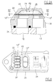
- FIGS 6 and 7 illustrate an embodiment in which the valve 10B in question differs from the three-way valve previously described, in that it has five ways.
- valve 10B comprises:
- the body 30 also contains two pairs of inner passages, similarly to the case of the three-way valve, i.e. a first pair, comprising two passages P1a and P2a, and a second pair, comprising two passages P1b and P2b.
- a first inner passage P1a, P1b which connects the primary intake 11 to a respective primary usage way 13a and 13b
- a second inner passage P2a, P2b which connects the same primary usage way 13a, 13b to a respective primary outlet 12a and 12b.
- the said inner passages are the same as those for the three-way valve, and each comprise a respective transit chamber, indicated respectively as 23a, 24a in the first pair, and 23b, 24b in the second pair. Into each chamber there opens an adjacent pair of inlets:
- a respective means for closure of the flow comprising a respective membrane 21a, 21b, 22a, 22b.
- each usage way 53 (of the first valve 50) and 63 (of the second valve 60) is divided into two branches.
- the way 53 is divided into two branches 53a, 53b which are connected respectively to the chamber 23a of the first passage P1a of the first pair, and to the chamber 24b of the second passage P2b of the second pair;
- the way 63 is divided into two branches 63a, 63b, which are connected to the chamber 24a of the second passage P2a of the first pair, and to the chamber 23b of the first passage P1b of the second pair.
- the piloting means introduce into the chamber 23a of the first passage P1a of the first pair, and into the chamber 24b of the second passage P2b of the second pair, a pilot fluid which has a pressure which can thrust the membrane into the said first position, in order to prevent passage of the fluid, and simultaneously to discharge the chamber 24a of the second passage P2a of the first pair, and the chamber 23b of the first passage P1b of the second pair, in order to allow the membrane to go into the said second position, such as to permit passage of the fluid; and vice versa.
- piloting means operate similarly to the manner described for the version with three ways; the only difference is that one pair of passages P1a and P2a operates in a manner which is symmetrically opposed to the other pair of passages P1b and P2b; this means that when, in the first pair, the first passage P1a is closed and the second passage P2a is opened, simultaneously, in the second pair, the first passage P1b is opened and the second passage P2b is closed; and vice versa.
- the transit chambers 23a and 24b are pressurised, such as to close the corresponding passages P1a and P2b, and simultaneously the other chambers 24a and 23b are discharged, such as to open the corresponding passages P2a and P1b (as illustrated in figure 6).
- the intake 11 is connected only to the second usage way 13b, and thus to the second user (for example the chamber 16" of the jack 16), whereas the first user (chamber 16') is discharged via the first usage way 13a, which communicates with the discharge 12a.
- the transit chambers 24a and 23b are pressurised, such as to close the corresponding passages P2a and P1b, and simultaneously the other chambers 23a and 24b are discharged, such as to open the corresponding passages P1a and P2b.
- the intake 11 is connected only to the first usage way 13b, and thus to the first user (for example the chamber 16' of the jack 16), whereas the second user (chamber 16") is discharged via the second usage way 13b, which communicates with the discharge 12b.
- the valve body 30 comprises a lower body 31, an intermediate body 32, and an upper body 33, which are substantially flat, and are rendered integral with one another in the form of a sandwich, with the respective horizontal surfaces adhering firmly to one another.
- the primary intake/outlet ways i.e. the primary intake 11, the primary outlet 12, and the usage way 13.
- the intermediate body 32 there are provided the inlets 11', 12', 13" and 12", which open onto the upper surface of the body 32 (which thus defines the base 25 of the chambers 23 and 24).
- the transit chambers 23 and 24 are provided in the form of concavities which face downwards onto the lower surface of the upper body 33.
- the membranes 21 and 22 are clamped firmly along their own peripheral part, between the lower surface of the upper body 33 and the upper surface of the intermediate body 32, and separate the chambers 23, 24 from the base 25 beneath, onto which the said inlets 11', 13', 13" and 12" open (see in particular figures 2 and 3).
- the lower body 31 there are provided the primary intake 11, the primary outlets 12a and 12b, and the usage ways 13a and 13b.
- the intermediate body 32 there are provided the various inlets 11'a, 11'b, 13'a, 13'b, 13"a, 13"b, 12"a and 12"b, which open onto the upper surface of the body 32 (which thus defines the base 25 of the transit chambers 23a, 23b, 24a and 24b).
- These transit chambers are provided in the form of concavities which face downwards onto the lower surface of the first component 331 (i.e. the lower surface of the upper body 33).
- the membranes 21a, 21b, 22a and 22b are clamped firmly along their own peripheral part, between the lower surface of the upper body 33 and the upper surface of the intermediate body 32, and separate the transit chambers 23a, 23b, 24a and 24b from the base 25 beneath, onto which the said inlets 11'a, 11'b, 13'a, 13'b, 13"a, 13"b, 12"a and 12"b open.
- the first piloting valve 50 is contained in the same valve body 30.
- the upper body 33 which, according to the embodiment illustrated in figure 7, consists of several flat components which are joined together in the form of a sandwich, which in turn is connected to the two bodies beneath it, i.e. 32 and 31.
- the various ducts 51, 52, 53, 53a, 53b, 61, 62, 63, 63a, 63b which connect the primary ways to the pilot valves 50 and 60, and connect these valves to one another, are contained in the valve body 30, and in particular in the upper body 33.
- the body 33 comprises a first component 331, which is substantially flat, in the lower, horizontal surface of which the transit chambers are provided, and a second component 332, which is also flat, and adheres to the flat, horizontal upper surface of the first component 331.
- the second component 332 has a series of channels 39 which are suitably shaped, are recessed in its upper surface, are closed at the top by the lower surface of the third component 333, and give rise, at least partially, to the various connection ducts between the transit chambers and the pilot valves. Other ducts (not shown in the figures) are provided inside the upper body 33.
- an upper component 34 which acts as a connection for the ways for intake, discharge and usage of the second pilot valve 60, which is disposed on the exterior of the valve body 30, and is secured to the latter.
- the inlets which function in a discharged condition when they are closed have thin cross-pieces 37 (see figure 4), which act as a support grid, on which the corresponding membrane 21, 22 is disposed. These cross-pieces are used to decrease the downward flexure of the membrane when it is thrust under pressure, above the inlet itself, in order to prolong the life of the membrane itself.
- valve can function at frequencies which are relatively very high (up to 50 Hz), as a result of the low inertia of its moving parts, consisting only of the flexible membranes 21, 22 etc.
- valve can thus operate equally well at high or low temperatures.
Landscapes
- Engineering & Computer Science (AREA)
- Physics & Mathematics (AREA)
- Fluid Mechanics (AREA)
- Mechanical Engineering (AREA)
- General Engineering & Computer Science (AREA)
- Multiple-Way Valves (AREA)
- Magnetically Actuated Valves (AREA)
Applications Claiming Priority (2)
| Application Number | Priority Date | Filing Date | Title |
|---|---|---|---|
| IT1999RE000119A IT1311050B1 (it) | 1999-11-17 | 1999-11-17 | Valvola di controllo della direzione del flusso. |
| ITRE990119 | 1999-11-17 |
Publications (1)
| Publication Number | Publication Date |
|---|---|
| EP1101950A2 true EP1101950A2 (fr) | 2001-05-23 |
Family
ID=11399515
Family Applications (1)
| Application Number | Title | Priority Date | Filing Date |
|---|---|---|---|
| EP00202161A Withdrawn EP1101950A2 (fr) | 1999-11-17 | 2000-06-21 | Distributeur à voies multiples |
Country Status (2)
| Country | Link |
|---|---|
| EP (1) | EP1101950A2 (fr) |
| IT (1) | IT1311050B1 (fr) |
-
1999
- 1999-11-17 IT IT1999RE000119A patent/IT1311050B1/it active
-
2000
- 2000-06-21 EP EP00202161A patent/EP1101950A2/fr not_active Withdrawn
Also Published As
| Publication number | Publication date |
|---|---|
| IT1311050B1 (it) | 2002-02-28 |
| ITRE990119A0 (it) | 1999-11-17 |
| ITRE990119A1 (it) | 2001-05-17 |
Similar Documents
| Publication | Publication Date | Title |
|---|---|---|
| CA2102901C (fr) | Vanne de regulation | |
| AU7587200A (en) | Dual diaphragm pump | |
| US3760843A (en) | Multi-way directional fluid flow control valve arrangement | |
| WO2002070932A3 (fr) | Microvanne | |
| JPH0744560U (ja) | フロントカットオフバルブ | |
| CA1208102A (fr) | Clapet pilote d'admission et d'echappement | |
| JPH0694906B2 (ja) | 滑り弁 | |
| US4458718A (en) | Spool valve and seal having zero leakage | |
| EP1146234A3 (fr) | Système hydraulique avec soupape à siège fantôme | |
| KR102128375B1 (ko) | 3방향 전자밸브 | |
| CN1316189C (zh) | 流体阀装置 | |
| USRE29481E (en) | Multi-way directional fluid flow control valve arrangement | |
| EP1114954A2 (fr) | Soupape à deux voies | |
| EP1803980B1 (fr) | Soupape à piston creux | |
| US11448204B2 (en) | Diaphragm pump with valve switching device | |
| JPS62177379A (ja) | エアパイロツト式流路切換弁 | |
| EP1029185B1 (fr) | Agencement de soupape | |
| EP1101950A2 (fr) | Distributeur à voies multiples | |
| US3782682A (en) | Fluid flow controller | |
| EP2069662B1 (fr) | Élément d'étanchéité de soupape et soupape correspondante | |
| US20090026393A1 (en) | Mechanism for a flow control device with buffer chamber | |
| US4374485A (en) | Single annular membrane type of pneumatic positioner | |
| US2881801A (en) | Pilot-operated three-way valve | |
| JPH0238768A (ja) | 流体制御弁 | |
| EP1484540B1 (fr) | Membrane de commande, en particulier pour soupapes pneumatiques |
Legal Events
| Date | Code | Title | Description |
|---|---|---|---|
| PUAI | Public reference made under article 153(3) epc to a published international application that has entered the european phase |
Free format text: ORIGINAL CODE: 0009012 |
|
| AK | Designated contracting states |
Kind code of ref document: A2 Designated state(s): AT BE CH CY DE DK ES FI FR GB GR IE IT LI LU MC NL PT SE |
|
| AX | Request for extension of the european patent |
Free format text: AL;LT;LV;MK;RO;SI |
|
| 18D | Application deemed to be withdrawn |
Effective date: 20021231 |
|
| STAA | Information on the status of an ep patent application or granted ep patent |
Free format text: STATUS: THE APPLICATION IS DEEMED TO BE WITHDRAWN |
|
| R18D | Application deemed to be withdrawn (corrected) |
Effective date: 20030103 |