EP1101954B1 - Fixation par encliquetage - Google Patents
Fixation par encliquetage Download PDFInfo
- Publication number
- EP1101954B1 EP1101954B1 EP00120152A EP00120152A EP1101954B1 EP 1101954 B1 EP1101954 B1 EP 1101954B1 EP 00120152 A EP00120152 A EP 00120152A EP 00120152 A EP00120152 A EP 00120152A EP 1101954 B1 EP1101954 B1 EP 1101954B1
- Authority
- EP
- European Patent Office
- Prior art keywords
- detent
- connection
- housing
- gas bag
- retaining parts
- Prior art date
- Legal status (The legal status is an assumption and is not a legal conclusion. Google has not performed a legal analysis and makes no representation as to the accuracy of the status listed.)
- Expired - Lifetime
Links
- 239000011324 bead Substances 0.000 description 3
- 210000003128 head Anatomy 0.000 description 3
- 210000002414 leg Anatomy 0.000 description 3
- 238000002347 injection Methods 0.000 description 2
- 239000007924 injection Substances 0.000 description 2
- 230000015572 biosynthetic process Effects 0.000 description 1
- 238000006073 displacement reaction Methods 0.000 description 1
- 238000005755 formation reaction Methods 0.000 description 1
- 239000000463 material Substances 0.000 description 1
- 210000001331 nose Anatomy 0.000 description 1
- 239000007787 solid Substances 0.000 description 1
- 210000000689 upper leg Anatomy 0.000 description 1
Images


Classifications
-
- B—PERFORMING OPERATIONS; TRANSPORTING
- B60—VEHICLES IN GENERAL
- B60R—VEHICLES, VEHICLE FITTINGS, OR VEHICLE PARTS, NOT OTHERWISE PROVIDED FOR
- B60R21/00—Arrangements or fittings on vehicles for protecting or preventing injuries to occupants or pedestrians in case of accidents or other traffic risks
- B60R21/02—Occupant safety arrangements or fittings, e.g. crash pads
- B60R21/16—Inflatable occupant restraints or confinements designed to inflate upon impact or impending impact, e.g. air bags
- B60R21/20—Arrangements for storing inflatable members in their non-use or deflated condition; Arrangement or mounting of air bag modules or components
- B60R21/217—Inflation fluid source retainers, e.g. reaction canisters; Connection of bags, covers, diffusers or inflation fluid sources therewith or together
-
- F—MECHANICAL ENGINEERING; LIGHTING; HEATING; WEAPONS; BLASTING
- F16—ENGINEERING ELEMENTS AND UNITS; GENERAL MEASURES FOR PRODUCING AND MAINTAINING EFFECTIVE FUNCTIONING OF MACHINES OR INSTALLATIONS; THERMAL INSULATION IN GENERAL
- F16B—DEVICES FOR FASTENING OR SECURING CONSTRUCTIONAL ELEMENTS OR MACHINE PARTS TOGETHER, e.g. NAILS, BOLTS, CIRCLIPS, CLAMPS, CLIPS OR WEDGES; JOINTS OR JOINTING
- F16B2/00—Friction-grip releasable fastenings
- F16B2/02—Clamps, i.e. with gripping action effected by positive means other than the inherent resistance to deformation of the material of the fastening
Definitions
- the invention relates to a latching connection, in particular for a gas bag cover of a vehicle occupant restraint system, according to the preamble of claim 1.
- the other holding part has an opening.
- the locking lug is pressed by the other holding part until the opening is above the locking lug and this can snap.
- the latch is correspondingly movable, it must be formed of sufficiently thin material. However, this reduces the strength of the locking connection.
- a latching connection according to the preamble of claim 1 is known from US-A-5,876,060.
- the detent is disposed on a cantilevered tongue which is resiliently deflected when a tab is inserted between its associated guide.
- the invention provides a latching connection which avoids the disadvantages mentioned and which moreover is simple and inexpensive to produce and to use.
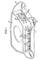
- the gas bag module in Figure 1 consists of a housing 10 and a gas bag cover 12.
- the housing 10 is substantially cuboid. On the side surfaces of the housing 10 holding parts 14, 14 'are mounted.
- the housing 10 may be designed as a plastic injection-molded part, wherein advantageously the holding parts 14, 14 'are mitangespritzt.
- the guide member 16 comprises a guide member 16 and two locking lugs 24.
- the guide member 16 consists of two guides 18 with L-shaped cross-section and a cross member 20.
- the guides 18 are fixedly attached to the end of their long legs on the housing, in such a way that their short thighs face each other. At the bottom of the picture, the short legs are connected by the cross member 20 with each other.
- the ends of the guides 18 together with the traverse 20 and the housing 10 form a passage 22.
- two locking lugs 24 are formed on the housing 10.
- the latching lugs 24 extend parallel to one another and have a ramp surface 26 and a flat, rounded head 28.
- the ramp surfaces 26 of the locking lugs 24 are facing the traverse 20.
- the locking lugs 24 are molded on the housing 10 as formations. Since they do not have to be movable, they have no undercuts. This ensures a cost-effective production, since no complicated injection mold is required. In addition, the locking lugs are very stable because they are connected at their entire base with the housing.
- the guides 18 are not parallel to each other, but starting from the passage 22 in the direction of the heads 28 of the locking lugs 24 towards each other. In this case, the shorter legs of the guides 18 taper in a wedge shape.
- Figure 1 it can be seen that on the longitudinal side of the housing 10, three such holding parts 14 are attached. On the narrow side of the housing 10, two holding parts 14 'are attached, which are each provided only with a latching lug. The same applies to the narrow side not visible in FIG. 1, while three guide elements 14, each with two latching noses, are again mounted on the non-visible longitudinal side.
- the number of holding parts per side and the type, whether with one, two or more locking lugs, is exemplified here and can be adjusted depending on the application, for example, on the size of the housing and the required connection force.
- FIG. 1 is also seen that on the housing 10 side facing the airbag cover 12, a bead 30 is formed.
- the airbag cover 12 is placed from below on the housing 10, so that the bead 30 encloses the lower edge of the housing 10.
- At the upper edge of the bead 30 holding parts in the form of tabs 32, 32 'are formed. These tabs 32, 32 'extend through the passages 22 and along the guides 18 of the holding parts 14, 14' on the housing 10.
- In the tabs 32, 32 'openings 34 are recessed, in which the locking lugs 24 engage. According to the number of locking lugs 24 are in the tabs 32, 32 'respectively two or an opening available.
- the gas bag cover 12 may advantageously be a plastic injection molded part.
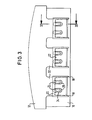
- the airbag cover 12 is pushed onto the housing, so that the tabs 32, 32 'pass through the passages 22.
- the height of the locking lugs determines the strength of the warping of the tabs. The higher the locking lugs are, but the larger is also the surface for the force that can be transmitted between the holding parts. However, the maximum possible warping is also limited by the thickness of the tabs. In the embodiment shown, the height of the locking lugs 24 is selected so that they just through the tabs 32, 32 'protrude. Thus, the maximum engagement surface for the connection force is present and the connection optimally secured against unintentional loosening. Namely, if the latches engage only partially in the openings, the tabs and the locking lugs could bend at a high connection force by acting on the attack surface moment. This would mean that the attack surface is no longer perpendicular to the connection force and therefore the tabs can slip off the locking lugs.
- a micro-tooth 34 is formed. Such a micro-toothing is shown in the enlarged section in FIG. 4.
- an airbag module is only an example of the application of the locking connection according to the invention. Numerous changes are conceivable, the holding parts with the guide elements and the locking lugs can just as well be attached to the gas bag cover and the tabs on the housing.
- the locking lugs may be attached to the tabs instead of the housing, wherein the ramp surface would have to point in the other direction.
- the openings would then be provided in the housing and omit the crossbar, so that the tabs curl when inserted into the guides until the latches can engage in the openings on the housing.
Landscapes
- Engineering & Computer Science (AREA)
- Mechanical Engineering (AREA)
- Air Bags (AREA)
- Snaps, Bayonet Connections, Set Pins, And Snap Rings (AREA)
Claims (5)
- Liaison par enclenchement, en particulier pour un couvercle de coussin à gaz (12) d'un système de retenue de passager de véhicule, comportant deux parties de retenue (14, 14', 32, 32') dont l'une des parties de retenue (14, 14') est pourvue d'au moins un ergot d'enclenchement (24), l'ergot d'enclenchement étant réalisé de telle sorte que l'une des parties de retenue (32, 32'), lors d'un déplacement des deux parties de retenue l'une par rapport à l'autre, est arquée par une force agissant sensiblement perpendiculairement à la direction de déplacement, avant que l'ergot d'enclenchement s'enclenche, ladite une partie de retenue (32, 32') étant réalisée sous forme de patte, et l'autre partie de retenue (14, 14') présentant des éléments de guidage (16) au moyen desquels la patte (32, 32') est guidée, caractérisée en ce que la patte (32, 32') est guidée par les éléments de guidage (16) de telle sorte qu'elle est arquée entre les deux éléments de guidage perpendiculairement à la direction de déplacement jusqu'à ce que l'ergot d'enclenchement vienne s'enclencher.
- Liaison par enclenchement selon la revendication 1, caractérisée en ce qu'une des parties de retenue (32, 32') présente au moins une ouverture (34) dans laquelle s'engage l'ergot d'enclenchement (24).
- Module de coussin à gaz comportant une liaison par enclenchement selon l'une des revendications précédentes, caractérisé en ce qu'une des parties de retenue (32, 32') est reliée de manière solidaire au couvercle (12).
- Module de coussin à gaz comportant une liaison par enclenchement selon l'une des revendications 1 et 2, caractérisé en ce qu'une des parties de retenue (14, 14') est reliée de manière solidaire au boîtier (10).
- Module de coussin à gaz comportant une liaison par enclenchement selon l'une des revendications 1 et 2, caractérisé en ce que l'ergot d'enclenchement (24) est pourvu d'une microdenture (34).
Applications Claiming Priority (2)
| Application Number | Priority Date | Filing Date | Title |
|---|---|---|---|
| DE29920024U DE29920024U1 (de) | 1999-11-15 | 1999-11-15 | Rastverbindung |
| DE29920024U | 1999-11-15 |
Publications (3)
| Publication Number | Publication Date |
|---|---|
| EP1101954A2 EP1101954A2 (fr) | 2001-05-23 |
| EP1101954A3 EP1101954A3 (fr) | 2002-12-11 |
| EP1101954B1 true EP1101954B1 (fr) | 2007-03-14 |
Family
ID=8081610
Family Applications (1)
| Application Number | Title | Priority Date | Filing Date |
|---|---|---|---|
| EP00120152A Expired - Lifetime EP1101954B1 (fr) | 1999-11-15 | 2000-09-21 | Fixation par encliquetage |
Country Status (3)
| Country | Link |
|---|---|
| US (1) | US6409208B1 (fr) |
| EP (1) | EP1101954B1 (fr) |
| DE (2) | DE29920024U1 (fr) |
Families Citing this family (15)
| Publication number | Priority date | Publication date | Assignee | Title |
|---|---|---|---|---|
| DE10016514B4 (de) * | 2000-04-03 | 2006-04-06 | Autoliv Development Ab | Lenkrad mit durch Verschiebung des Airbagmoduls ausgelöster Hupenfunktion |
| US20020024197A1 (en) * | 2000-08-30 | 2002-02-28 | Breed Automotive Technologies, Inc. | Air bag module |
| DE20113806U1 (de) | 2001-08-21 | 2002-02-28 | Breed Automotive Technology, Inc., Lakeland, Fla. | Airbagmodul mit Rastverbindung |
| US6752415B2 (en) * | 2001-10-05 | 2004-06-22 | Autoliv Asp, Inc. | Airbag module Z-height control tab |
| US6959943B2 (en) * | 2002-11-18 | 2005-11-01 | Autoliv Asp, Inc. | Deflectable airbag housing mounting tabs |
| DE202004004556U1 (de) * | 2004-03-23 | 2004-08-12 | Trw Automotive Gmbh | Abdeckung für ein Gassackmodul |
| DE102005004128B4 (de) * | 2004-03-23 | 2014-01-02 | Trw Automotive Gmbh | Abdeckung für ein Gassackmodul |
| US7374198B2 (en) * | 2004-04-02 | 2008-05-20 | Toyoda Gosei Co., Ltd | Airbag module canister |
| US7527286B2 (en) * | 2004-07-29 | 2009-05-05 | Intier Automotive Inc. | Air bag door and chute |
| DE102005027271B4 (de) | 2005-06-08 | 2011-06-01 | Takata-Petri Ag | Abdeckkappe für ein Airbagmodul |
| DE102010034114A1 (de) * | 2010-08-12 | 2012-02-16 | Gm Global Technology Operations Llc (N.D.Ges.D. Staates Delaware) | Airbaganordnung mit einem separaten Schusskanal |
| US8944460B2 (en) * | 2011-06-30 | 2015-02-03 | Ford Global Technologies, Llc | Air bag chute topper system |
| KR102146661B1 (ko) * | 2013-11-29 | 2020-08-21 | 현대모비스 주식회사 | 차량의 에어백 모듈 |
| US9415738B2 (en) | 2014-12-22 | 2016-08-16 | Ford Global Technologies, Llc | Anti-rattle interface for airbag chute to airbag module |
| KR102761183B1 (ko) * | 2020-04-10 | 2025-01-31 | 현대모비스 주식회사 | 운전석 에어백 장치 |
Family Cites Families (11)
| Publication number | Priority date | Publication date | Assignee | Title |
|---|---|---|---|---|
| JPH0694267B2 (ja) * | 1990-05-24 | 1994-11-24 | タカタ株式会社 | エアバッグ装置 |
| JP2567134Y2 (ja) * | 1993-01-22 | 1998-03-30 | 矢崎総業株式会社 | 二重係止コネクタ |
| JPH07233805A (ja) * | 1994-02-23 | 1995-09-05 | Unisia Jecs Corp | ユニット取付構造 |
| US5474323A (en) * | 1994-06-08 | 1995-12-12 | Takata, Inc. | Passenger air bag module with snap-attachment deployment cover |
| US5445409A (en) * | 1994-10-17 | 1995-08-29 | General Motors Corporation | Passenger airbag snap-on deployment door |
| US5511819A (en) * | 1995-03-27 | 1996-04-30 | Morton International, Inc. | Fastenerless automotive passenger airbag module endcap |
| US5588669A (en) * | 1995-04-26 | 1996-12-31 | Morton International, Inc. | Cover attachment for an air bag module |
| JP3651068B2 (ja) * | 1995-07-31 | 2005-05-25 | 豊田合成株式会社 | エアバッグ装置 |
| JP3155691B2 (ja) * | 1995-09-12 | 2001-04-16 | 矢崎総業株式会社 | 組付部品のロック構造 |
| JP3003578B2 (ja) * | 1996-07-22 | 2000-01-31 | 株式会社デンソー | 車両のエアバッグ装置用ケーシング及びそのカバー部材 |
| US5876060A (en) * | 1996-12-05 | 1999-03-02 | Takata, Inc. | Seat mounted side impact module |
-
1999
- 1999-11-15 DE DE29920024U patent/DE29920024U1/de not_active Expired - Lifetime
-
2000
- 2000-09-21 DE DE50014156T patent/DE50014156D1/de not_active Expired - Lifetime
- 2000-09-21 EP EP00120152A patent/EP1101954B1/fr not_active Expired - Lifetime
- 2000-09-29 US US09/675,605 patent/US6409208B1/en not_active Expired - Fee Related
Also Published As
| Publication number | Publication date |
|---|---|
| DE29920024U1 (de) | 2000-03-30 |
| US6409208B1 (en) | 2002-06-25 |
| EP1101954A2 (fr) | 2001-05-23 |
| DE50014156D1 (de) | 2007-04-26 |
| EP1101954A3 (fr) | 2002-12-11 |
Similar Documents
| Publication | Publication Date | Title |
|---|---|---|
| EP1101954B1 (fr) | Fixation par encliquetage | |
| EP2057043B1 (fr) | Dispositif pour fixer une unité d'airbag dans un sous-ensemble d'un véhicule automobile, en particulier dans un volant de direction, par enclenchement | |
| DE69508569T2 (de) | Sekundär anschluss verriegelungs element | |
| EP0129248B1 (fr) | Boucle pour ceinture de sécurité | |
| DE202009015649U1 (de) | Schubkasten und Trennelement für einen Schubkasten | |
| EP1255650A1 (fr) | Timbre auto-encreur | |
| EP2183736B1 (fr) | Dispositif d'identification pour lignes électriques | |
| DE2515842C2 (de) | Schraubenlose Klemme | |
| DE1557427B1 (de) | Verschlussschnalle fuer einen Sicherheitsgurt | |
| DE2510807B2 (de) | Elektrisches Gerät zur Befestigung an einer Unterlage | |
| EP1489712B1 (fr) | Soulagement de contrainte pour câble électrique | |
| DE10056835A1 (de) | Gassack-Modulgehäuse | |
| DE19600236A1 (de) | Gehäuseelement eines elektrischen Verbinders | |
| DE4202819C2 (de) | Verschluß für Sicherheits-Gurte | |
| WO2006024438A1 (fr) | Module de connexion electrique | |
| DE4301949C2 (de) | Steckkontaktbuchse für einen Flachsteckstift | |
| DE10035726A1 (de) | Kontaktträger | |
| EP1243078B1 (fr) | Appareil electrique pourvu d'un boitier | |
| DE20109717U1 (de) | Kopfstützenhülse für eine Führungsstange einer Kopfstütze | |
| EP2117083B1 (fr) | Connecteur à fiches électrique | |
| DE60027072T2 (de) | Elektrische Steckverbindung, insbesondere für Kraftfahrzeuganwendungen | |
| EP0989760B1 (fr) | Bloc de connection pour la technique de télécommunications | |
| EP0093236B1 (fr) | Fiche pour appareil | |
| DE20217461U1 (de) | Elektrischer Steckverbinder | |
| DE3136755A1 (de) | "vorrichtung zur aufnahme von kassetten mit, mit mindestens einem nach aussen ausfahrbaren verriegelungselement versehenen verriegelungsmechanismus" |
Legal Events
| Date | Code | Title | Description |
|---|---|---|---|
| PUAI | Public reference made under article 153(3) epc to a published international application that has entered the european phase |
Free format text: ORIGINAL CODE: 0009012 |
|
| AK | Designated contracting states |
Kind code of ref document: A2 Designated state(s): AT BE CH CY DE DK ES FI FR GB GR IE IT LI LU MC NL PT SE |
|
| AX | Request for extension of the european patent |
Free format text: AL;LT;LV;MK;RO;SI |
|
| RIN1 | Information on inventor provided before grant (corrected) |
Inventor name: DERRICK, JOHN-OLIVER Inventor name: FRISCH, RALPH |
|
| PUAL | Search report despatched |
Free format text: ORIGINAL CODE: 0009013 |
|
| AK | Designated contracting states |
Kind code of ref document: A3 Designated state(s): AT BE CH CY DE DK ES FI FR GB GR IE IT LI LU MC NL PT SE |
|
| AX | Request for extension of the european patent |
Free format text: AL;LT;LV;MK;RO;SI |
|
| 17P | Request for examination filed |
Effective date: 20030605 |
|
| AKX | Designation fees paid |
Designated state(s): DE ES FR GB IT |
|
| GRAP | Despatch of communication of intention to grant a patent |
Free format text: ORIGINAL CODE: EPIDOSNIGR1 |
|
| GRAS | Grant fee paid |
Free format text: ORIGINAL CODE: EPIDOSNIGR3 |
|
| GRAA | (expected) grant |
Free format text: ORIGINAL CODE: 0009210 |
|
| AK | Designated contracting states |
Kind code of ref document: B1 Designated state(s): DE ES FR GB IT |
|
| RAP1 | Party data changed (applicant data changed or rights of an application transferred) |
Owner name: TRW AUTOMOTIVE SAFETY SYSTEMS GMBH |
|
| REG | Reference to a national code |
Ref country code: GB Ref legal event code: FG4D Free format text: NOT ENGLISH |
|
| REF | Corresponds to: |
Ref document number: 50014156 Country of ref document: DE Date of ref document: 20070426 Kind code of ref document: P |
|
| PG25 | Lapsed in a contracting state [announced via postgrant information from national office to epo] |
Ref country code: ES Free format text: LAPSE BECAUSE OF FAILURE TO SUBMIT A TRANSLATION OF THE DESCRIPTION OR TO PAY THE FEE WITHIN THE PRESCRIBED TIME-LIMIT Effective date: 20070625 |
|
| GBV | Gb: ep patent (uk) treated as always having been void in accordance with gb section 77(7)/1977 [no translation filed] |
Effective date: 20070314 |
|
| EN | Fr: translation not filed | ||
| EN | Fr: translation not filed | ||
| PG25 | Lapsed in a contracting state [announced via postgrant information from national office to epo] |
Ref country code: GB Free format text: LAPSE BECAUSE OF FAILURE TO SUBMIT A TRANSLATION OF THE DESCRIPTION OR TO PAY THE FEE WITHIN THE PRESCRIBED TIME-LIMIT Effective date: 20070314 |
|
| PLBE | No opposition filed within time limit |
Free format text: ORIGINAL CODE: 0009261 |
|
| STAA | Information on the status of an ep patent application or granted ep patent |
Free format text: STATUS: NO OPPOSITION FILED WITHIN TIME LIMIT |
|
| 26N | No opposition filed |
Effective date: 20071217 |
|
| PG25 | Lapsed in a contracting state [announced via postgrant information from national office to epo] |
Ref country code: IT Free format text: LAPSE BECAUSE OF FAILURE TO SUBMIT A TRANSLATION OF THE DESCRIPTION OR TO PAY THE FEE WITHIN THE PRESCRIBED TIME-LIMIT Effective date: 20070314 Ref country code: FR Free format text: LAPSE BECAUSE OF FAILURE TO SUBMIT A TRANSLATION OF THE DESCRIPTION OR TO PAY THE FEE WITHIN THE PRESCRIBED TIME-LIMIT Effective date: 20071102 |
|
| PG25 | Lapsed in a contracting state [announced via postgrant information from national office to epo] |
Ref country code: FR Free format text: LAPSE BECAUSE OF FAILURE TO SUBMIT A TRANSLATION OF THE DESCRIPTION OR TO PAY THE FEE WITHIN THE PRESCRIBED TIME-LIMIT Effective date: 20070314 |
|
| PGFP | Annual fee paid to national office [announced via postgrant information from national office to epo] |
Ref country code: DE Payment date: 20190930 Year of fee payment: 20 |
|
| REG | Reference to a national code |
Ref country code: DE Ref legal event code: R071 Ref document number: 50014156 Country of ref document: DE |