EP1102020B1 - Méchanisme de positionnement d'un réfrigérateur cryogénique pour formation d'images par résonance magnétique - Google Patents
Méchanisme de positionnement d'un réfrigérateur cryogénique pour formation d'images par résonance magnétique Download PDFInfo
- Publication number
- EP1102020B1 EP1102020B1 EP00310013A EP00310013A EP1102020B1 EP 1102020 B1 EP1102020 B1 EP 1102020B1 EP 00310013 A EP00310013 A EP 00310013A EP 00310013 A EP00310013 A EP 00310013A EP 1102020 B1 EP1102020 B1 EP 1102020B1
- Authority
- EP
- European Patent Office
- Prior art keywords
- cryocooler
- slider
- assembly
- sealed cavity
- magnet
- Prior art date
- Legal status (The legal status is an assumption and is not a legal conclusion. Google has not performed a legal analysis and makes no representation as to the accuracy of the status listed.)
- Expired - Lifetime
Links
- 238000002595 magnetic resonance imaging Methods 0.000 title 1
- 230000000712 assembly Effects 0.000 claims description 8
- 238000000429 assembly Methods 0.000 claims description 8
- 238000003780 insertion Methods 0.000 claims description 7
- 230000037431 insertion Effects 0.000 claims description 7
- 239000001307 helium Substances 0.000 description 13
- 229910052734 helium Inorganic materials 0.000 description 13
- SWQJXJOGLNCZEY-UHFFFAOYSA-N helium atom Chemical compound [He] SWQJXJOGLNCZEY-UHFFFAOYSA-N 0.000 description 13
- 239000007788 liquid Substances 0.000 description 8
- 239000007789 gas Substances 0.000 description 5
- RYGMFSIKBFXOCR-UHFFFAOYSA-N Copper Chemical compound [Cu] RYGMFSIKBFXOCR-UHFFFAOYSA-N 0.000 description 4
- 229910052802 copper Inorganic materials 0.000 description 4
- 239000010949 copper Substances 0.000 description 4
- 238000009835 boiling Methods 0.000 description 3
- 239000000696 magnetic material Substances 0.000 description 2
- 230000013011 mating Effects 0.000 description 2
- 238000010791 quenching Methods 0.000 description 2
- 230000005855 radiation Effects 0.000 description 2
- 208000027418 Wounds and injury Diseases 0.000 description 1
- 238000007792 addition Methods 0.000 description 1
- 230000006378 damage Effects 0.000 description 1
- 230000007423 decrease Effects 0.000 description 1
- 230000003247 decreasing effect Effects 0.000 description 1
- 230000001934 delay Effects 0.000 description 1
- 210000005069 ears Anatomy 0.000 description 1
- 238000003384 imaging method Methods 0.000 description 1
- 208000014674 injury Diseases 0.000 description 1
- 230000003993 interaction Effects 0.000 description 1
- 238000012423 maintenance Methods 0.000 description 1
- 230000007257 malfunction Effects 0.000 description 1
- 230000000737 periodic effect Effects 0.000 description 1
- 230000000171 quenching effect Effects 0.000 description 1
- 238000004064 recycling Methods 0.000 description 1
- 238000012827 research and development Methods 0.000 description 1
- 238000007789 sealing Methods 0.000 description 1
- 229910001220 stainless steel Inorganic materials 0.000 description 1
- 239000010935 stainless steel Substances 0.000 description 1
Images
Classifications
-
- F—MECHANICAL ENGINEERING; LIGHTING; HEATING; WEAPONS; BLASTING
- F25—REFRIGERATION OR COOLING; COMBINED HEATING AND REFRIGERATION SYSTEMS; HEAT PUMP SYSTEMS; MANUFACTURE OR STORAGE OF ICE; LIQUEFACTION SOLIDIFICATION OF GASES
- F25D—REFRIGERATORS; COLD ROOMS; ICE-BOXES; COOLING OR FREEZING APPARATUS NOT OTHERWISE PROVIDED FOR
- F25D19/00—Arrangement or mounting of refrigeration units with respect to devices or objects to be refrigerated, e.g. infrared detectors
- F25D19/006—Thermal coupling structure or interface
-
- H—ELECTRICITY
- H01—ELECTRIC ELEMENTS
- H01F—MAGNETS; INDUCTANCES; TRANSFORMERS; SELECTION OF MATERIALS FOR THEIR MAGNETIC PROPERTIES
- H01F6/00—Superconducting magnets; Superconducting coils
- H01F6/04—Cooling
Definitions
- This invention relates to superconducting magnet according to the preamble of claim 1.
- Such a magnet is known from document US 4 535 595.
- a superconducting magnet can be made superconducting by placing it in an extremely cold environment, such as by enclosing it in a cryostat or pressure vessel containing liquid helium or other liquid cryogen.
- the extreme cold ensures that the magnet coils are maintained in superconducting operation, such that when a power source is initially connected to the magnet coils for a short period of time to introduce a current flow through the coils, the current will continue to flow through the coils even after power is removed due to the absence of electrical resistance in the coils, thereby maintaining a strong magnetic field.
- Superconducting magnet assemblies find wide application in the field of MRI.
- cryogen gas recondensing systems utilizing a mechanical refrigerator or cryocooler to cool the cryogen gas and recondense it back to liquid cryogen for reuse.
- cryocooler system which minimizes the difficulties in properly positioning the cryocooler in the sealed cavity, and obtaining during the short ride-through period good thermal contact between the cryocooler, magnet, and recondenser.
- a superconducting magnet according to the invention has the features defined in claim 1.
- the guide assembly includes a hollow tube with a mounting bracket for securing it to the magnet outside and adjacent the sealed cavity.
- the slider assembly includes a slider rod dimensioned to pass through and beyond the hollow tube of the guide assembly and brackets for mounting the rod to the cryocooler warm end flange.
- the slider rod is substantially longer than the hollow tube such that the rod can be guided and inserted into the hollow tube while the cryocooler is outside the sealed cavity and positioned in a low field or low strength area of the magnetic field generated by the operating superconducting magnet.
- the combination of the rod and guide assemblies avoids misalignments and potentially poor thermal contact between the cryocooler and magnet that might otherwise result from the magnetic field forces acting on the cryocooler. This facilitates rapid removal and replacement of the cryocooler while the superconducting magnet is operating at field.
- a threaded fastener passing through the guide tube and contacting the slider rod secures the rod and cryocooler in position after good thermal contact is obtained between the cryocooler and sealed cavity thermal interfaces to maintain the good thermal contact.
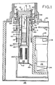
- two-stage cryocooler 10 includes housing 8 forming an internal cylindrical bore 12 in which displacer 14 is driven by an AC drive motor (not shown) through a mechanical drive as indicated by arrow 9 along axis 21 of the cryocooler and also of sealed cavity 22 which is described below in the manner well known in the art.
- Cryocooler 10 is inserted into sealed cavity 22 formed by walls 4 and flange 13 within MRI superconducting magnet 30.
- cryocooler 10 reduces the temperature of cryogen recondensing apparatus 32 to which it is thermally connected to superconducting temperatures.
- the thermal connection is made through separable thermal joints or thermal interface 50 which includes copper thermal member 47 on cryocooler 10 and copper thermal member 49 within MRI superconducting magnet 30 and forming the bottom surface of cavity 22. This enables the removal of cryocooler 10 without breaking the vacuum within superconducting magnet 30 or discontinuing superconducting operation of the magnet.
- Recondenser 32 provides recondensing and recycling of the boiled cryogen, typically helium gas resulting from the boiling of liquid helium from helium reservoir 36 within pressurized vessel 35 to cool main magnet coils 34 to superconducting temperatures and provide a strong magnetic field in the imaging volume in bore 38.
- the boiled cryogen typically helium gas resulting from the boiling of liquid helium from helium reservoir 36 within pressurized vessel 35 to cool main magnet coils 34 to superconducting temperatures and provide a strong magnetic field in the imaging volume in bore 38.
- Helium gas is passed between recondensing surfaces 40 to be recondensed and returned via return 44 as liquid helium to the liquid helium reservoir indicated generally as 36 within pressurized vessel 35 of MRI superconducting magnet 30.
- Recondensing surfaces 40 are formed by slots in thermal member 54 through which the helium gas flows to be recondensed. The result is a zero boiloff closed loop helium boiling and recondensing system without the need to replenish boiled helium by periodic additions of external liquid helium.
- Thermal radiation shield 9 is thermally connected to the first stage of cryocooler 10 through braided copper wires (not shown) connected to the thermal interface between sealed cavity 22 and the cryocooler.
- cryocooler 10 From time to time it becomes necessary to replace cryocooler 10 due to malfunctions of the cryocooler or the need to perform routine maintenance. It is highly desirable to rapidly remove cryocooler 10 from sealed cavity 22 to provide a replacement cryocooler without disturbing the superconducting operation of magnet 30 in order to avoid MRI downtime, and the time and expense which would otherwise result if the magnet were to quench or cease superconducting operation and have to be subsequently ramped up and placed back into superconducting operation.
- cryocooler 10 thus must be accomplished in the relatively short time period available before liquid helium 34 boils off causing a discontinuance of superconducting operation of coils 34, the so-called ride-through period.
- the magnetic field generated by superconducting coils 34 exerts strong magnetic forces on the magnetic material, such as stainless steel, of cryocooler 10.
- the magnetic forces tend to pull the cryocooler out of alignment, or centered, within sealed cavity 22 which in turn prevents good thermal contact between the surfaces of the thermal interfaces such as the copper thermal members 47 and 49 of thermal joint 50.
- the lack of good thermal contact in thermal joint 50 can interfere with and/or prevent the necessary recondensing action provided by recondenser 32.
- One or more combinations 82 of cooperating guide assembly 52 and slider or rod assembly 70 are provided to position and axially guide cryocooler 10 into sealed cavity 22.
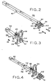
- the details of guide assembly 52 and slider assembly 70 are shown in Figs. 2-4.
- guide assembly 52 includes a central axial aperture 54 through mounting bracket 56 and guide tube 58.
- Aperture 54 is shown as rectangular in cross-section which is desirable for positive positioning if only a single set of cooperating guide 52 and slider 60 assemblies are utilized.
- Aperture 54 could be of other cross-sections such as circular, particularly if a plurality of cooperating guide assembly 52 and slider assembly combinations 82 are utilized around the periphery of cryocooler 10.
- slider assembly 70 includes a slider rod 60 and mounting brackets 57 and 61.
- Rod 60 is dimensioned to fit closely but slidably within aperture 54 of guide assembly 52.
- guide tube 58 is considerably shorter than slider rod 60, and in one application the guide tube was 24.13 cm (9.5 inches) long while slider rod 60 was 60.96 cm (24 inches) long.
- rod 60 is in tubular form including hollow center or aperture 64.
- Guide tube 58 is 3.57 x 3.17 cm (1.25 x 1.25 inches) with a wall thickness of 0.28 cm (0.11 inches) and aperture 54 has an internal dimension of 2.90 x 2.90 cm (1.14 x 1.14 inches).
- Rod 60 is 2.54 x 2.54 cm (1.00 x 1.00 inches) providing a nominal total clearance of 0.36 cm (0.14 inches between) opposite sides of aperture 54 of guide assembly 52 to facilitate insertion and withdrawal of cryocooler 10 to which the rod is secured.
- guide assembly 52 is positioned adjacent but outside sealed cavity 22 by attachment to flange 13 of superconducting magnet 30.
- Bolts 53 pass through apertures 55 in flange 13 to threaded openings 57 in ears 59 of mounting bracket 56.
- slider assembly 70 is secured to warm end flange 15 of cryocooler 10 through mounting bracket 62 which includes a pair of plates 57 and 61 which are positioned on opposite sides of flange 15 which surrounds and closes the warm upper end of sealed cavity 22.
- Bolts 59 pass through apertures 63 in plate 61 to threaded apertures 65 in plate 57 to sandwich cryocooler flange 15 and clamp slider assembly 70 to cryocooler 10.
- the extended length of slider rod 60 is adequate to enable the alignment of the slider rod and its insertion into aperture 54 of guide 52 while cryocooler 10 is positioned above and outside the internal regions of sealed cavity 22. This enables engagement and insertion of the slider rod 60 without significant magnetic field attraction of the magnetic field generated by superconducting magnet coils 34 on cryocooler 22 avoiding the strong force tending to pull cryocooler 10 out of axial alignment in sealed cavity 22.
- slider rod 60 is slid into tube 58 while cryocooler 10 is in a region of lower magnetic field, after which the tube and slider combination 82 accurately guides the axis of cryocooler 30 along axis 21 while resisting the strong magnetic attraction from the magnetic field generated by superconducting coils 34 as the cryocooler is lowered into sealed cavity 22.
- This decreases the possibility of misalignment of cryocooler 10 and improper thermal mating of the thermal interfaces by ensuring fully parallel and centered mating surfaces of thermal members such as 47 and 49 of thermal interface or joint 50.
- Guide assembly 52 and rod 60 of slider assembly 70 also minimize the force and weight which a field engineer must overcome and handle in installing cryocooler 10 into sealed cavity 22, decreasing the chance of an injury to, and contributing to the safety of the installer or field engineer.
- a pair of diametrically opposed guide and slider combinations 82 may be utilized, and slider rod 60, aperture 54 and tube 58 could be of circular or other cross-section.
- Threaded retaining bolt 80 passes through threaded member 83 and guide tube 58 to contact slider rod 60 to retain the rod and attach cryocooler 10 in position after the cryocooler in inserted and proper thermal contact is obtained at thermal interfaces such as 50.
- the operation of this fastener may be facilitated by utilizing knurling 81 for bolt 80.
Landscapes
- Engineering & Computer Science (AREA)
- Power Engineering (AREA)
- Chemical & Material Sciences (AREA)
- Combustion & Propulsion (AREA)
- Physics & Mathematics (AREA)
- Mechanical Engineering (AREA)
- Thermal Sciences (AREA)
- General Engineering & Computer Science (AREA)
- Magnetic Resonance Imaging Apparatus (AREA)
Claims (7)
- Aimant supraconducteur (30) comprenant une cuve sous vide renfermant une cavité étanche (22), cavité (22) dans laquelle est placé un dispositif de refroidissement cryogénique et comprenant un ensemble de positionnement adapté pour guider et positionner le dispositif de refroidissement cryogénique (10) dans la cavité étanche (22), l'ensemble de positionnement comprenant :une paire d'ensembles coopérants (52, 70) comprenant un ensemble de coulisseau s'étendant dans le sens axial (70), lui-même comprenant une tige à extension axiale (60), et un ensemble de guidage (52) comprenant une ouverture s'étendant dans le sens axial (54) dimensionnée de manière à recevoir et guider ledit coulisseau (70) ;ledit ensemble de coulisseau s'étendant dans le sens axial (70) étant fixé audit dispositif de refroidissement cryogénique (10) afin d'être solidaire de son mouvement, et ledit ensemble de guidage (52) étant fixé à ladite cuve sous vide en dehors et à proximité de ladite cavité étanche ;lesdits ensembles de guidage et de coulisseau étant positionnés de façon à permettre l'insertion axiale sélective dudit dispositif de refroidissement cryogénique dans ladite cavité étanche tout en guidant ledit dispositif de refroidissement cryogénique afin de maintenir l'alignement axial dudit dispositif de refroidissement cryogénique (10) dans ladite cavité étanche (22) en dépit des forces magnétiques provenant du champ magnétique dudit aimant supraconducteur (30) qui agissent pour forcer ledit dispositif de refroidissement cryogénique hors d'alignement ;caractérisé en ce que
la longueur développée de la tige de coulisseau (60) est adéquate pour permettre l'alignement de la tige de coulisseau et son insertion dans l'ouverture de l'ensemble de guidage (52) alors que le dispositif de refroidissement cryogénique est positionné au-dessus et en dehors des régions internes de ladite cavité étanche (22) ;
lesdits ensembles (52, 70) coopèrent pour faciliter l'insertion dudit dispositif de refroidissement cryogénique (10) dans ladite cavité étanche (22) durant le fonctionnement dudit aimant supraconducteur. - Aimant selon la revendication 1, dans lequel ledit dispositif de refroidissement cryogénique (10) comprend une bride d'extrémité chaude (15) distante de l'intérieur dudit aimant supraconducteur, et ledit ensemble de coulisseau (70) est fixé à ladite bride (15).
- Aimant selon la revendication 2, dans lequel ledit ensemble de guidage (52) est soudé sur l'extérieur de ladite cavité étanche (22) et ledit ensemble de coulisseau (70) est boulonné sur ladite bride d'extrémité chaude (15) du dispositif de refroidissement cryogénique.
- Aimant selon la revendication 1, dans lequel est présente une pluralité de combinaisons dudit ensemble de coulisseau (70) et dudit ensemble de guidage (52) entourant ladite cavité étanche (22).
- Aimant selon la revendication 2, dans lequel l'ensemble de positionnement dudit dispositif de refroidissement cryogénique (10) comprend également un mécanisme de verrouillage sélectif comprenant un membre fileté rotatif (80) traversant des filets coopérants formés dans ledit ensemble de guidage (52) pour contacter ledit ensemble de coulisseau (70) pour fixer ledit dispositif de refroidissement cryogénique (10) positionné dans ladite cavité étanche (22).
- Aimant selon la revendication 4, dans lequel ledit ensemble de coulisseau (70) comprend une paire de plaques parallèles (57, 61) positionnées sur des côtés opposés de ladite bride d'extrémité chaude (15), et des boulons traversent lesdites plaques pour fixer ledit coulisseau à ladite bride d'extrémité chaude (15).
- Aimant selon la revendication 1, dans lequel est présente une pluralité de combinaisons dudit ensemble de coulisseau (70) et dudit ensemble de guidage (52) positionnées autour dudit dispositif de refroidissement cryogénique (10), dont chacune comprend une ouverture tubulaire axiale (54) et une tige à extension axiale (60) coopérantes.
Applications Claiming Priority (2)
| Application Number | Priority Date | Filing Date | Title |
|---|---|---|---|
| US09/442,182 US6144274A (en) | 1999-11-16 | 1999-11-16 | Magnetic resonance imaging cryocooler positioning mechanism |
| US442182 | 1999-11-16 |
Publications (3)
| Publication Number | Publication Date |
|---|---|
| EP1102020A2 EP1102020A2 (fr) | 2001-05-23 |
| EP1102020A3 EP1102020A3 (fr) | 2002-08-21 |
| EP1102020B1 true EP1102020B1 (fr) | 2007-03-07 |
Family
ID=23755840
Family Applications (1)
| Application Number | Title | Priority Date | Filing Date |
|---|---|---|---|
| EP00310013A Expired - Lifetime EP1102020B1 (fr) | 1999-11-16 | 2000-11-10 | Méchanisme de positionnement d'un réfrigérateur cryogénique pour formation d'images par résonance magnétique |
Country Status (4)
| Country | Link |
|---|---|
| US (1) | US6144274A (fr) |
| EP (1) | EP1102020B1 (fr) |
| JP (1) | JP2001198105A (fr) |
| DE (1) | DE60033763T2 (fr) |
Families Citing this family (9)
| Publication number | Priority date | Publication date | Assignee | Title |
|---|---|---|---|---|
| JP4040626B2 (ja) * | 2002-12-16 | 2008-01-30 | 住友重機械工業株式会社 | 冷凍機の取付方法及び装置 |
| GB0411603D0 (en) * | 2004-05-25 | 2004-06-30 | Oxford Magnet Tech | Electromagnetic shield for refrigerator |
| US9494540B2 (en) | 2006-08-21 | 2016-11-15 | Aspect Ai Ltd. | System and method for a nondestructive on-line testing of samples |
| US8069675B2 (en) * | 2006-10-10 | 2011-12-06 | Massachusetts Institute Of Technology | Cryogenic vacuum break thermal coupler |
| US8729894B2 (en) * | 2010-07-30 | 2014-05-20 | General Electric Company | System and method for operating a magnetic resonance imaging system during ramping |
| RU2606036C2 (ru) | 2011-09-28 | 2017-01-10 | Конинклейке Филипс Н.В. | Высокоэффективный теплообменник для свободного от криогена магнита для магнитно-резонансной томографии (mri) |
| GB2509087A (en) * | 2012-12-19 | 2014-06-25 | Siemens Plc | Sealed rotary drive arrangement, providing drive into a high-pressure gas vessel |
| DE202014104677U1 (de) | 2014-09-15 | 2014-10-22 | Aspect Ai Ltd. | Temperaturgesteuerte austauschbare NMR-Fühlerkassette |
| CN108006084B (zh) * | 2017-11-20 | 2019-08-16 | 北京鼎臣世纪超导科技有限公司 | 一种零摩擦超导磁悬浮轴承装置 |
Family Cites Families (4)
| Publication number | Priority date | Publication date | Assignee | Title |
|---|---|---|---|---|
| US4535595A (en) * | 1983-02-09 | 1985-08-20 | Bruker Analytische Mebtechnik Gmbh | Cooling device for a low temperature magnet system |
| US5522226A (en) * | 1995-09-12 | 1996-06-04 | General Electric Company | Positive retraction mechanism for cryogenic thermal joints |
| US5613367A (en) * | 1995-12-28 | 1997-03-25 | General Electric Company | Cryogen recondensing superconducting magnet |
| US6029458A (en) * | 1998-05-07 | 2000-02-29 | Eckels; Phillip William | Helium recondensing magnetic resonance imager superconducting shield |
-
1999
- 1999-11-16 US US09/442,182 patent/US6144274A/en not_active Expired - Fee Related
-
2000
- 2000-11-10 EP EP00310013A patent/EP1102020B1/fr not_active Expired - Lifetime
- 2000-11-10 DE DE60033763T patent/DE60033763T2/de not_active Expired - Fee Related
- 2000-11-15 JP JP2000347435A patent/JP2001198105A/ja not_active Withdrawn
Also Published As
| Publication number | Publication date |
|---|---|
| JP2001198105A (ja) | 2001-07-24 |
| EP1102020A3 (fr) | 2002-08-21 |
| DE60033763D1 (de) | 2007-04-19 |
| EP1102020A2 (fr) | 2001-05-23 |
| US6144274A (en) | 2000-11-07 |
| DE60033763T2 (de) | 2007-12-06 |
Similar Documents
| Publication | Publication Date | Title |
|---|---|---|
| EP1102020B1 (fr) | Méchanisme de positionnement d'un réfrigérateur cryogénique pour formation d'images par résonance magnétique | |
| EP1460444B1 (fr) | Système de refrigération cryogénique à tube pulsé pour des aimants supraconducteurs pour la résonance magnétique | |
| US5744959A (en) | NMR measurement apparatus with pulse tube cooler | |
| EP0260036B1 (fr) | Assemblage de cryostat | |
| US5613367A (en) | Cryogen recondensing superconducting magnet | |
| EP0905434B1 (fr) | Améliorations dans ou relatives à des systèmes de cryostats | |
| EP0209134A1 (fr) | Dispositif de bobine à supraconduction avec refroidissement par circulation forcée | |
| EP0720024B1 (fr) | Aimant supraconducteur à recondensation d'hélium | |
| US5442928A (en) | Hybrid cooling system for a superconducting magnet | |
| CN106098290B (zh) | 超导磁体 | |
| US9864022B2 (en) | Superconducting magnet device and magnetic resonance imaging device | |
| JPH10213357A (ja) | 冷凍剤再凝縮システム | |
| EP1808870B1 (fr) | Électroaimant supraconducteur | |
| EP1587114A2 (fr) | Dispositif magnétique supraconducteur | |
| WO2016109235A1 (fr) | Système et procédé de refroidissement pour dispositif d'imagerie par résonance magnétique | |
| JPH09120912A (ja) | 開構造伝導冷却型磁気共鳴作像マグネット | |
| EP0820071B1 (fr) | Procédé de refroidissement et procédé d'alimentation d'un superconducteur | |
| EP0772013B1 (fr) | Mécanisme de rétractation positive pour joints thermiques cryogéniques | |
| US20110179808A1 (en) | Neck deicer for liquid helium recondensor of magnetic resonance system | |
| US12112887B2 (en) | Switch assemblies of superconducting magnet assemblies and reconfigurable superconducting magnet assemblies of a cryogenic system | |
| WO2006122594A1 (fr) | Appareil et procede pour l'installation de tubes de refroidissement dans un composant refroidi | |
| GB2467598A (en) | Refrigerator isolation valve for cryogen vessel | |
| JP6895510B2 (ja) | 原子炉制御棒駆動装置で使用するための移動可能な隔離された棒結合 | |
| CN222213847U (zh) | 用于磁体的冷却系统、磁体以及超导型磁共振成像设备 | |
| US12283416B2 (en) | Switch assemblies of superconducting magnet assemblies and reconfigurable superconducting magnet assemblies of a cryogenic system |
Legal Events
| Date | Code | Title | Description |
|---|---|---|---|
| PUAI | Public reference made under article 153(3) epc to a published international application that has entered the european phase |
Free format text: ORIGINAL CODE: 0009012 |
|
| AK | Designated contracting states |
Kind code of ref document: A2 Designated state(s): AT BE CH CY DE DK ES FI FR GB GR IE IT LI LU MC NL PT SE TR |
|
| AX | Request for extension of the european patent |
Free format text: AL;LT;LV;MK;RO;SI |
|
| PUAL | Search report despatched |
Free format text: ORIGINAL CODE: 0009013 |
|
| AK | Designated contracting states |
Kind code of ref document: A3 Designated state(s): AT BE CH CY DE DK ES FI FR GB GR IE IT LI LU MC NL PT SE TR |
|
| AX | Request for extension of the european patent |
Free format text: AL;LT;LV;MK;RO;SI |
|
| 17P | Request for examination filed |
Effective date: 20030221 |
|
| AKX | Designation fees paid |
Designated state(s): DE GB NL |
|
| 17Q | First examination report despatched |
Effective date: 20040507 |
|
| GRAP | Despatch of communication of intention to grant a patent |
Free format text: ORIGINAL CODE: EPIDOSNIGR1 |
|
| GRAS | Grant fee paid |
Free format text: ORIGINAL CODE: EPIDOSNIGR3 |
|
| GRAA | (expected) grant |
Free format text: ORIGINAL CODE: 0009210 |
|
| AK | Designated contracting states |
Kind code of ref document: B1 Designated state(s): DE GB NL |
|
| REG | Reference to a national code |
Ref country code: GB Ref legal event code: FG4D |
|
| REF | Corresponds to: |
Ref document number: 60033763 Country of ref document: DE Date of ref document: 20070419 Kind code of ref document: P |
|
| PLBE | No opposition filed within time limit |
Free format text: ORIGINAL CODE: 0009261 |
|
| STAA | Information on the status of an ep patent application or granted ep patent |
Free format text: STATUS: NO OPPOSITION FILED WITHIN TIME LIMIT |
|
| 26N | No opposition filed |
Effective date: 20071210 |
|
| GBPC | Gb: european patent ceased through non-payment of renewal fee |
Effective date: 20071110 |
|
| NLV4 | Nl: lapsed or anulled due to non-payment of the annual fee |
Effective date: 20080601 |
|
| PG25 | Lapsed in a contracting state [announced via postgrant information from national office to epo] |
Ref country code: NL Free format text: LAPSE BECAUSE OF NON-PAYMENT OF DUE FEES Effective date: 20080601 Ref country code: DE Free format text: LAPSE BECAUSE OF NON-PAYMENT OF DUE FEES Effective date: 20080603 |
|
| PG25 | Lapsed in a contracting state [announced via postgrant information from national office to epo] |
Ref country code: GB Free format text: LAPSE BECAUSE OF NON-PAYMENT OF DUE FEES Effective date: 20071110 |