EP1102023B1 - Geschossansetzer für Artillerie - Google Patents
Geschossansetzer für Artillerie Download PDFInfo
- Publication number
- EP1102023B1 EP1102023B1 EP00123207A EP00123207A EP1102023B1 EP 1102023 B1 EP1102023 B1 EP 1102023B1 EP 00123207 A EP00123207 A EP 00123207A EP 00123207 A EP00123207 A EP 00123207A EP 1102023 B1 EP1102023 B1 EP 1102023B1
- Authority
- EP
- European Patent Office
- Prior art keywords
- carriage
- linear motor
- projectile
- rammer according
- projectile rammer
- Prior art date
- Legal status (The legal status is an assumption and is not a legal conclusion. Google has not performed a legal analysis and makes no representation as to the accuracy of the status listed.)
- Expired - Lifetime
Links
- 230000001133 acceleration Effects 0.000 claims description 15
- 230000033001 locomotion Effects 0.000 claims description 13
- 239000006096 absorbing agent Substances 0.000 claims description 4
- 230000035939 shock Effects 0.000 claims description 4
- 239000003302 ferromagnetic material Substances 0.000 claims description 3
- 230000005291 magnetic effect Effects 0.000 claims description 3
- 230000001360 synchronised effect Effects 0.000 claims description 2
- 239000000843 powder Substances 0.000 claims 1
- 230000000979 retarding effect Effects 0.000 claims 1
- 238000000034 method Methods 0.000 description 10
- 230000008569 process Effects 0.000 description 10
- 238000011161 development Methods 0.000 description 3
- 230000018109 developmental process Effects 0.000 description 3
- 230000006403 short-term memory Effects 0.000 description 3
- XEEYBQQBJWHFJM-UHFFFAOYSA-N Iron Chemical compound [Fe] XEEYBQQBJWHFJM-UHFFFAOYSA-N 0.000 description 2
- 230000008901 benefit Effects 0.000 description 2
- 230000001419 dependent effect Effects 0.000 description 2
- 238000012546 transfer Methods 0.000 description 2
- 230000004308 accommodation Effects 0.000 description 1
- 230000006399 behavior Effects 0.000 description 1
- 238000010276 construction Methods 0.000 description 1
- 238000013461 design Methods 0.000 description 1
- 238000010586 diagram Methods 0.000 description 1
- 238000010304 firing Methods 0.000 description 1
- 230000006870 function Effects 0.000 description 1
- 238000003780 insertion Methods 0.000 description 1
- 230000037431 insertion Effects 0.000 description 1
- 229910052742 iron Inorganic materials 0.000 description 1
- 238000002360 preparation method Methods 0.000 description 1
- 230000003797 telogen phase Effects 0.000 description 1
- 230000009466 transformation Effects 0.000 description 1
- 230000001960 triggered effect Effects 0.000 description 1
- 239000013585 weight reducing agent Substances 0.000 description 1
- 230000003936 working memory Effects 0.000 description 1
Images


Classifications
-
- F—MECHANICAL ENGINEERING; LIGHTING; HEATING; WEAPONS; BLASTING
- F41—WEAPONS
- F41A—FUNCTIONAL FEATURES OR DETAILS COMMON TO BOTH SMALLARMS AND ORDNANCE, e.g. CANNONS; MOUNTINGS FOR SMALLARMS OR ORDNANCE
- F41A9/00—Feeding or loading of ammunition; Magazines; Guiding means for the extracting of cartridges
- F41A9/38—Loading arrangements, i.e. for bringing the ammunition into the firing position
- F41A9/39—Ramming arrangements
- F41A9/42—Rammers separate from breech-block
Definitions
- the invention relates to a bullet for artillery with the features from the preamble of claim 1.
- the principle of the free-flight tappet is that one outside the Gun projectile located such a high speed is that this after leaving the acceleration system due the kinetic energy caused by the acceleration in the open air Flight continues to move and the piecing process is realized in this way.
- the in the abovementioned publication such as, for example, in CH 664 627 described free-flying piecing have for accelerating a carriage system, in which the projectile stored on the carriage including the Sled is accelerated and when reaching the required piecing speed the carriage is braked. The projectile then flies through the bottom piece in the cargo space of the weapon and is in the trains of the Weapon tube attached.
- pneumatic (EP 0 352 584 A2) or hydraulic (CH 664 627) drive devices used as Piston-cylinder drives are formed, wherein the respective operation Medium is stored in a working memory and by means of a special Control valve abruptly the piston-cylinder drive is supplied.
- the spring device as a drive device, For example, electromotive biased coil springs or use gas springs, which mechanically triggered during piecing and the stored energy via downstream machine components (Chains, racks) on the bullet or attachment sled transfer.
- the document DE 3208941 A1 discloses the use of an electro-linear motor Drive on the control of a straight pull closure one described automatic weapon.
- this known application is the closure body from a catching position in the rear region of his Trajectory accelerated to the fire opening, leaving a ready Ammunition unit for insertion into the barrel and takes to the Shot development is locked. Through a part of the shot development released energy of the closure body is unlocked again and bounces back, banging into a stop buffer and doing so its direction of movement to initiate a subsequent firing cycle reverses.
- the invention is based on the object, a free-flying piecing for artillery with the beginning and in the preamble of claim 1 specified Characteristics in such a way that in the drive device electrical Energy is converted directly into kinetic energy and thus the loss of efficiency by converting the electrical energy into one other form of energy is avoided.
- the invention is based on the recognition that the realization of such Drive device driven by conventional electric motors Systems to implement the required for the moment of piecing high electrical energy in the translatory carriage movement fails.
- this machine components known in engineering (chains, spindles, gears, Racks) due to the mass forces occurring during acceleration and the high, attachment speeds to the limits of their capacity.
- the required power and its weight accommodation for example Arrangement on a movable loading arm, hardly realizable.
- a basic idea of the invention therefore consists in replacing the known, designed as a piston-cylinder drive drive device a electric linear motor to use.
- Linear motors allow direct Generation of linear movements without the interposition of gears.
- the force is generated directly on the part to be moved. All mechanical Intermediate links are eliminated, and the electrical energy becomes direct supplied in the existing form and does not need in another form of energy to be transformed.
- Another advantage of trained as a linear motor Drive device is that in contrast to the piston-cylinder drive, its thrust until the end of the acceleration stroke developed, the acceleration process and a possible deceleration process in the linear motor is very precisely controlled. This is done by an electrical control device, by which the movement on Linear motor depending on the distance covered and / or the Direction of movement and / or the elevation of the gun barrel according to predetermined Values is controllable, the control device with measuring devices for the distance traveled and / or the direction of movement and / or the elevation of the gun barrel is connected.
- the drive power is turned off in the braking phase or the other way around.
- the linear motor thus develops an additional Braking force in the design of the means for braking the carriage can be taken into account.
- the electrical supply of the linear motor can at a in one Combat vehicle arranged gun from a powered by the electrical system Battery buffer done.
- a short-term memory can be used whose capacity is designed for a piecing process.
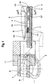
- Fig. 1 shows the rear end of the gun barrel 1 of a rest not shown artillery gun on which the bottom piece 1.1 is arranged.
- a weapon On the gun barrel 1 is a combinschwenkbarer about the trunnion axis S.
- Projectile transfer arm 2 which at its outer end a support 3 carries on which a Geschoßansetzer is arranged.
- Above the carrier 3 is a guideway 4.3 attached to the on a roller guide 4.1 a Carriage 4 is guided in the direction parallel to the Rohrseelenachse R.
- a shell-like attack element 4.2 At the rear End of the carriage 4 is a shell-like attack element 4.2 as a driver for lying on the carriage in a receiving trough 4.4 Bullet G.
- a known and unspecified shock absorber 7 is arranged, the stop 7.1 in the illustrated in Fig. 2 end position of the carriage 4 at the rear end of the Gun barrel rests.
- the carriage 4 moves from the rest position shown in FIG. 1 into the end position shown in FIG. 2, in Fig. 2, the beginning of the end position with solid lines and the after retraction of the shock absorber 7 final end position shown in phantom is.
- the projectile moves G in free flight into the gun barrel 1 inside.
- the drive device for accelerating the carriage 4, in the in 1 to 3 illustrated embodiment, an electric linear motor on with an elongated flat, between the carrier 3 and the Carriage 4 fixed primary part 5, in a in Figs. 1 and 2 not shown connected to the electrical supply device is.
- the movable secondary part 6 of the linear motor is as an elongated flat Component formed and made of ferromagnetic material, for example made of iron with a magnetic track 6.1.
- the secondary part 6 passes over the lying flat primary part 5.
- a tightening force occurs in twice the maximum feed force between the primary and secondary parts on, which must be transmitted from the carriage guide 4.1-4.3.
- Figure 3 Of the Space for the shock absorber, not shown, is designated in Figure 3 with 7.2.
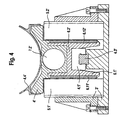
- Fig. 4 shows a drive device equipped with two linear motors is. Components in Fig. 4, corresponding to corresponding components of Fig. 3, are marked with the same reference number and an apostrophe line.
- the carriage 4 via a linear guide 4.1' in a central guide rail 4.3 'out.
- the primary parts 5.1 'and 5.2' of Linear motors are arranged on both sides of the carriage 4 'fixed in the carrier 3'.
- the primary parts 5.1 'and 5.2' are opposite to the two Sides of the carriage designed as outwardly facing components, made of ferromagnetic material secondary parts 6.1 'and 6.2' arranged, each carrying a magnetic track 6.11 'and 6.12' wear.
- Primary and Secondary parts are thus here in the vertical direction and opposite each other aligned.
- the length of the carriage can be shortened to the length of the secondary part which results in a weight reduction.
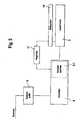
- the supply device has a, for example, to the electrical system of the combat vehicle connected battery buffer 9.
- the battery buffer 9 For as synchronous machines trained linear motors must the existing DC voltage on the for the operation of the linear motor or the linear motors required AC voltage be transformed. This is done by means of a to the battery buffer 9 connected converters 8.
- the piecing process at short notice a high electrical power must be available, contains the inverter. 8 a short-term memory 8.1, whose capacity designed for a piecing process is.
- An electrical measuring system 10 mounted on the attachment slide 4 or 4 ' monitors the sequence of the piecing process and controls via a control 11 targeted the delivery of electrical power from the short-term memory 8.1 to the primary part 5 of the linear motor.
- the control can be carried out according to any predetermined control characteristics, according to which the sled accelerates in the different phases of movement or slowed down.
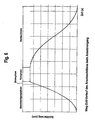
- Fig. 6 shows an example of the path-time course of the attachment slide during the starting process with an acceleration phase, a braking phase, a rest phase and a return phase.
Landscapes
- Engineering & Computer Science (AREA)
- General Engineering & Computer Science (AREA)
- Linear Motors (AREA)
- Connection Of Motors, Electrical Generators, Mechanical Devices, And The Like (AREA)
- Pharmaceuticals Containing Other Organic And Inorganic Compounds (AREA)
- Manufacturing Of Micro-Capsules (AREA)
- Hard Magnetic Materials (AREA)
- Electric Propulsion And Braking For Vehicles (AREA)
- Aiming, Guidance, Guns With A Light Source, Armor, Camouflage, And Targets (AREA)
- Toys (AREA)
- Motorcycle And Bicycle Frame (AREA)
- Control Of Electric Motors In General (AREA)
Description
Claims (11)
- Geschossansetzer für Artillerie mit einem hinter dem Geschütz angeordneten Schlitten (4, 4'), der eine fluchtend zum Ladungsraum angeordnete Aufnahmemulde (4.4) mit einem Angriffselement(4.2) am hinteren Ende für das Geschoss (G) trägt und über eine Führung (4.1) bewegbar auf einer parallel zur Geschützrohrachse verlaufenden Führungsbahn (4.3) geführt ist und der mit einer Antriebsvorrichtung zur Beschleunigung in Richtung auf das Geschützrohr (1) gekoppelt ist, wobei Mittel zur Abbremsung des Schlittens (4, 4') in einem vorgegebenen Abstand vor dem hinteren Ende des Geschützrohres (1) vorgesehen sind, dadurch gekennzeichnet, dass die Antriebsvorrichtung mit mindestens einem elektrischen Linearmotor (5-6, 5.1'-6.1', 5.2'-6.2') ausgerüstet ist und der Bewegungsablauf am Linearmotor durch eine elektrische Steuereinrichtung (11) in Abhängigkeit von der zurückgelegten Wegstrecke und/oder der Bewegungsrichtung und/oder der Elevation des Geschützrohres (1) gemäß vorgegebenen Werten steuerbar ist, wobei die Steuereinrichtung (11) mit Messgeräten (10) für die zurückgelegte Wegstrecke und/oder die Bewegungsrichtung und/oder die Elevation des Geschützrohres verbunden ist und die Abbremsung der Schlittenbewegung mindestens zum Teil durch generatorische Bremsung mittels des Linearmotors erfolgt
- Geschossansetzer nach Anspruch 1, dadurch gekennzeichnet, dass Primärteil (5, 5.1'. 5.2') und Sekundärteil (6, 6.1', 6.2') des Linearmotors so angeordnet sind, dass der Sekundärteil nach einer vorgegebenen Wegstrecke den Einwirkungsbereich des Primärteils verlässt.
- Geschossansetzer nach Anspruch 1 oder 2, dadurch gekennzeichnet dass der Primärteil (5, 5.1', 5.2') des Linearmotors, an dem die Stromzuführung erfolgt, fest mit der Führungsbahn (4.3, 4.3') verbunden ist, währen der Sekundärteil (6, 6.1', 6.2') mit dem Schlitten (4, 4') verbunden ist.
- Geschossansetzer nach Anspruch 3, dadurch gekennzeichnet, dass der Primärteil (5) des Linearmotors eine vorgegebene größere Länge besitzt als der Sekundärteil (6).
- Geschossansetzer nach einem der Ansprüche 1 bis 4, dadurch gekennzeichnet, dass der Sekundärteil (6, 6.1', 6.2') des Linearmotors aus einem länglichen, flachen Bauelement aus ferromagnetischem Material mit einer Magnetspur (6.1, 6.11', 6.12') besteht.
- Geschossansetzer nach einem der Ansprüche 1 bis 5, dadurch gekennzeichnet, dass die Stromversorgungseinrichtung für den Linearmotor einen elektrischen Kurzzeitspeicher (8.1) aufweist.
- Geschossansetzer nach Anspruch 6, dadurch gekennzeichnet, dass beim Einsatz des Geschossansetzers in einem Kampffahrzeug die Stromversorgungseinrichtung für den Linearmotor einen an das Bordnetz angeschlossenen Batteriepuffer (9) aufweist.
- Geschossansetzer nach einem der Ansprüche 6 oder 7, dadurch gekennzeichnet, dass bei einem als Synchronmotor ausgebildeten Linearmotor die Stromversorgungseinrichtung einen Wechselrichter (8) enthält.
- Geschossansetzer nach einem der Ansprüche 1 bis 8, dadurch gekennzeichnet, dass zwischen den Schlitten (4) und das hintere Ende des Geschutzrohres (1) eine als Stoßdämpfer (7) ausgebildete Bremsvorrichtung eingeschaltet ist.
- Geschossansetzer nach einem der Ansprüche 1 bis 9, dadurch gekennzeichnet, dass die Antriebsvorrichtung einen Linearmotor aufweist, dessen Primärteil (5) flach und nach oben weisend unterhalb des Schlittens (4) fest angeordnet ist, während an der Unterseite des Schlittens (4) der als längliches flaches Bauelement ausgebildeten Sekundärteil (6) befestigt ist.
- Geschossansetzer nach einem der Ansprüche 1 bis 10, dadurch gekennzeichnet, dass die Antriebsvorrichtung zwei Linearmotoren aufweist, deren Primärteile (5.1', 5.2') zu beiden Seiten des Schlittens (4') fest angeordnet sind, während an den Seiten des Schlittens (4') jeweils die als nach außen weisende Bauelemente ausgebildeten Sekundärteile (6.1', 6.2') befestigt sind.
Applications Claiming Priority (2)
| Application Number | Priority Date | Filing Date | Title |
|---|---|---|---|
| DE19955234 | 1999-11-17 | ||
| DE19955234A DE19955234A1 (de) | 1999-11-17 | 1999-11-17 | Geschoßansetzer für Artillerie |
Publications (3)
| Publication Number | Publication Date |
|---|---|
| EP1102023A2 EP1102023A2 (de) | 2001-05-23 |
| EP1102023A3 EP1102023A3 (de) | 2002-02-06 |
| EP1102023B1 true EP1102023B1 (de) | 2005-11-16 |
Family
ID=7929307
Family Applications (1)
| Application Number | Title | Priority Date | Filing Date |
|---|---|---|---|
| EP00123207A Expired - Lifetime EP1102023B1 (de) | 1999-11-17 | 2000-10-26 | Geschossansetzer für Artillerie |
Country Status (6)
| Country | Link |
|---|---|
| US (1) | US6467389B1 (de) |
| EP (1) | EP1102023B1 (de) |
| AT (1) | ATE310223T1 (de) |
| DE (2) | DE19955234A1 (de) |
| ES (1) | ES2251340T3 (de) |
| PL (1) | PL193246B1 (de) |
Families Citing this family (8)
| Publication number | Priority date | Publication date | Assignee | Title |
|---|---|---|---|---|
| WO2005003672A1 (en) * | 2003-07-02 | 2005-01-13 | Denel (Pty) Ltd | Ammunition loading assembly |
| FR2945616B1 (fr) * | 2009-05-13 | 2011-07-29 | Nexter Systems | Dispositif de chargement d'une munition |
| CN103776296B (zh) * | 2014-01-17 | 2015-06-10 | 中国船舶重工集团公司第七一〇研究所 | 多功能手动装退弹推杆 |
| DE102014017554B4 (de) * | 2014-11-28 | 2021-12-23 | Thyssenkrupp Ag | Vorrichtung zum Ausstoßen eines Objekts aus einem Waffenrohr mit einem Linearmotor |
| DE102019203071B4 (de) * | 2019-03-06 | 2022-04-28 | Thyssenkrupp Ag | Brückenlose Waffenmulde |
| DE102019211285B3 (de) * | 2019-07-30 | 2020-09-24 | Thyssenkrupp Ag | Waffenbrücke |
| FR3123977B1 (fr) * | 2021-06-15 | 2024-02-23 | Nexter Systems | Dispositif de mise a poste d'un projectile |
| US12173981B2 (en) | 2021-10-13 | 2024-12-24 | Moab Ventures Llc | Launching system for an air gun |
Family Cites Families (10)
| Publication number | Priority date | Publication date | Assignee | Title |
|---|---|---|---|---|
| FR1595414A (de) * | 1968-12-19 | 1970-06-08 | ||
| DE2455994C3 (de) * | 1974-11-27 | 1980-01-10 | Mak Maschinenbau Gmbh, 2300 Kiel | Vorrichtung zum Ausstoßen bzw. Ablaufen von Tauch- und Schwimmkörpern aus Rohren |
| DE2460507C3 (de) * | 1974-12-20 | 1979-12-06 | Walter 6600 Saarbruecken Landsrath | Schießgerät für in einem Rohr zu beschleunigende Geschosse |
| DE3208941C2 (de) * | 1982-03-12 | 1985-10-10 | Rheinmetall GmbH, 4000 Düsseldorf | Vorrichtung zum Übertragen von Energie auf den Verschlußkörper eines Geradzugverschlusses einer automatischen Rohrwaffe |
| US4555972A (en) * | 1982-12-20 | 1985-12-03 | Westinghouse Electric Corp. | Electromagnetic launcher with powder driven projectile insertion |
| US4791850A (en) * | 1986-01-23 | 1988-12-20 | Minovitch Michael Andrew | Electromagnetic launching system for long-range guided munitions |
| CH664627A5 (de) | 1986-11-20 | 1988-03-15 | Sig Schweiz Industrieges | Beschleunigungseinrichtung fuer eine ladevorrichtung eines geschuetzes. |
| DE3644513C1 (de) * | 1986-12-24 | 1992-08-27 | Dornier Gmbh | Munitionszufuehrung |
| DE3825662A1 (de) * | 1988-07-28 | 1990-02-08 | Wegmann & Co | Geschossansetzer fuer artillerie |
| DE3940421A1 (de) * | 1989-12-07 | 1991-06-13 | Wegmann & Co | Vorrichtung zur zufuehrung von treibladungen fuer rohrwaffen groesseren kalibers |
-
1999
- 1999-11-17 DE DE19955234A patent/DE19955234A1/de not_active Withdrawn
-
2000
- 2000-10-26 AT AT00123207T patent/ATE310223T1/de active
- 2000-10-26 DE DE50011622T patent/DE50011622D1/de not_active Expired - Lifetime
- 2000-10-26 ES ES00123207T patent/ES2251340T3/es not_active Expired - Lifetime
- 2000-10-26 EP EP00123207A patent/EP1102023B1/de not_active Expired - Lifetime
- 2000-11-08 US US09/708,144 patent/US6467389B1/en not_active Expired - Fee Related
- 2000-11-15 PL PL343880A patent/PL193246B1/pl unknown
Also Published As
| Publication number | Publication date |
|---|---|
| EP1102023A3 (de) | 2002-02-06 |
| US6467389B1 (en) | 2002-10-22 |
| ATE310223T1 (de) | 2005-12-15 |
| PL193246B1 (pl) | 2007-01-31 |
| ES2251340T3 (es) | 2006-05-01 |
| PL343880A1 (en) | 2001-05-21 |
| DE50011622D1 (de) | 2005-12-22 |
| DE19955234A1 (de) | 2001-05-23 |
| EP1102023A2 (de) | 2001-05-23 |
Similar Documents
| Publication | Publication Date | Title |
|---|---|---|
| EP0303761B1 (de) | Vorrichtung für einen nach vorn gerichteten Hülsenauswurf einer fremdangetriebenen Maschinenkanone | |
| EP1102023B1 (de) | Geschossansetzer für Artillerie | |
| DE102008060215A1 (de) | Antrieb und Schnellstop für eine Waffe mit vorzugsweise linearer Verschluss- bzw. Munitionszuführung | |
| EP2359085A1 (de) | Verschlussantrieb für eine waffe | |
| DE2331607A1 (de) | Vorrichtung zur halterung einer ladung | |
| DE2501426C2 (de) | ||
| DE102017101705A1 (de) | Fügevorrichtung, Beladestation, Zuführanordnung und Verfahren zum Beladen eines Magazins | |
| DE102011106489B4 (de) | Lastträger für ein Fluggerät | |
| DE60025506T2 (de) | Verfahren und vorrichtung zum laden einer artilleriekanone mit einem automatischen ansetzer | |
| DE102014213795A1 (de) | Waffentransportsystem für ein Unterseeboot | |
| DE2460391C3 (de) | Automatische Rohrwaffe | |
| EP1736726B1 (de) | Treibladungszuführungssystem | |
| DE1960023C1 (de) | Automatische Waffe zum Abfeuern von Patronen | |
| DE3113413A1 (de) | "transportradanordnung fuer hochgeschwindigkeits-feuer-revolvierende batteriegeschuetze" | |
| DE1264296B (de) | Ladevorrichtung fuer Waffen, wie Maschinengewehre und Kanonen | |
| DE3208942C2 (de) | Maschinenkanone mit zwei zum Vor- und Rücklauf nebeneinander in einem Waffengehäuse angeordneten Waffenrohren | |
| EP1050736A2 (de) | Kampffahrzeug, insbesondere Kampfpanzer | |
| EP3781893A1 (de) | Autolader sowie fahrzeug mit einem autolader | |
| EP1043561B1 (de) | Waffensimulator für ein Kampffahrzeug, insbesondere einen Kampfpanzer | |
| DE3216813A1 (de) | Verschluss- lader- anordnung an einer maschinenkanone | |
| DE3208941C2 (de) | Vorrichtung zum Übertragen von Energie auf den Verschlußkörper eines Geradzugverschlusses einer automatischen Rohrwaffe | |
| DE102024129301B3 (de) | Federantriebseinrichtung mit einem Federelement | |
| DE1933352B2 (de) | Anordnung einer Rohrwaffe mit zwei Startvomchtungen für Lenkflug korper | |
| EP2898282B1 (de) | Treibladungsansetzer, waffe und verfahren zum ansetzen von treibladungen | |
| EP0627608B1 (de) | Automatischer Ansetzer für Artilleriegeschosse |
Legal Events
| Date | Code | Title | Description |
|---|---|---|---|
| PUAI | Public reference made under article 153(3) epc to a published international application that has entered the european phase |
Free format text: ORIGINAL CODE: 0009012 |
|
| AK | Designated contracting states |
Kind code of ref document: A2 Designated state(s): AT BE CH CY DE DK ES FI FR GB GR IE IT LI LU MC NL PT SE |
|
| AX | Request for extension of the european patent |
Free format text: AL;LT;LV;MK;RO;SI |
|
| PUAL | Search report despatched |
Free format text: ORIGINAL CODE: 0009013 |
|
| AK | Designated contracting states |
Kind code of ref document: A3 Designated state(s): AT BE CH CY DE DK ES FI FR GB GR IE IT LI LU MC NL PT SE |
|
| AX | Request for extension of the european patent |
Free format text: AL;LT;LV;MK;RO;SI |
|
| 17P | Request for examination filed |
Effective date: 20020315 |
|
| AKX | Designation fees paid |
Free format text: AT BE CH CY DE DK ES FI FR GB GR IE IT LI LU MC NL PT SE |
|
| 17Q | First examination report despatched |
Effective date: 20030918 |
|
| GRAP | Despatch of communication of intention to grant a patent |
Free format text: ORIGINAL CODE: EPIDOSNIGR1 |
|
| GRAS | Grant fee paid |
Free format text: ORIGINAL CODE: EPIDOSNIGR3 |
|
| GRAA | (expected) grant |
Free format text: ORIGINAL CODE: 0009210 |
|
| AK | Designated contracting states |
Kind code of ref document: B1 Designated state(s): AT BE CH CY DE DK ES FI FR GB GR IE IT LI LU MC NL PT SE |
|
| PG25 | Lapsed in a contracting state [announced via postgrant information from national office to epo] |
Ref country code: IE Free format text: LAPSE BECAUSE OF FAILURE TO SUBMIT A TRANSLATION OF THE DESCRIPTION OR TO PAY THE FEE WITHIN THE PRESCRIBED TIME-LIMIT Effective date: 20051116 Ref country code: FI Free format text: LAPSE BECAUSE OF FAILURE TO SUBMIT A TRANSLATION OF THE DESCRIPTION OR TO PAY THE FEE WITHIN THE PRESCRIBED TIME-LIMIT Effective date: 20051116 |
|
| REG | Reference to a national code |
Ref country code: GB Ref legal event code: FG4D Free format text: NOT ENGLISH |
|
| REG | Reference to a national code |
Ref country code: CH Ref legal event code: EP |
|
| REG | Reference to a national code |
Ref country code: IE Ref legal event code: FG4D Free format text: LANGUAGE OF EP DOCUMENT: GERMAN |
|
| REF | Corresponds to: |
Ref document number: 50011622 Country of ref document: DE Date of ref document: 20051222 Kind code of ref document: P |
|
| GBT | Gb: translation of ep patent filed (gb section 77(6)(a)/1977) |
Effective date: 20051205 |
|
| REG | Reference to a national code |
Ref country code: CH Ref legal event code: NV Representative=s name: A. BRAUN, BRAUN, HERITIER, ESCHMANN AG PATENTANWAE |
|
| PG25 | Lapsed in a contracting state [announced via postgrant information from national office to epo] |
Ref country code: DK Free format text: LAPSE BECAUSE OF FAILURE TO SUBMIT A TRANSLATION OF THE DESCRIPTION OR TO PAY THE FEE WITHIN THE PRESCRIBED TIME-LIMIT Effective date: 20060216 |
|
| REG | Reference to a national code |
Ref country code: SE Ref legal event code: TRGR |
|
| REG | Reference to a national code |
Ref country code: GR Ref legal event code: EP Ref document number: 20050403955 Country of ref document: GR |
|
| PG25 | Lapsed in a contracting state [announced via postgrant information from national office to epo] |
Ref country code: PT Free format text: LAPSE BECAUSE OF FAILURE TO SUBMIT A TRANSLATION OF THE DESCRIPTION OR TO PAY THE FEE WITHIN THE PRESCRIBED TIME-LIMIT Effective date: 20060417 |
|
| REG | Reference to a national code |
Ref country code: ES Ref legal event code: FG2A Ref document number: 2251340 Country of ref document: ES Kind code of ref document: T3 |
|
| ET | Fr: translation filed | ||
| REG | Reference to a national code |
Ref country code: IE Ref legal event code: FD4D |
|
| PLBE | No opposition filed within time limit |
Free format text: ORIGINAL CODE: 0009261 |
|
| STAA | Information on the status of an ep patent application or granted ep patent |
Free format text: STATUS: NO OPPOSITION FILED WITHIN TIME LIMIT |
|
| 26N | No opposition filed |
Effective date: 20060817 |
|
| PG25 | Lapsed in a contracting state [announced via postgrant information from national office to epo] |
Ref country code: MC Free format text: LAPSE BECAUSE OF NON-PAYMENT OF DUE FEES Effective date: 20061031 |
|
| BERE | Be: lapsed |
Owner name: KRAUSS-MAFFEI WEGMANN G.M.B.H. & CO. KG Effective date: 20061031 |
|
| REG | Reference to a national code |
Ref country code: CH Ref legal event code: PFA Owner name: KRAUSS-MAFFEI WEGMANN GMBH & CO. KG Free format text: KRAUSS-MAFFEI WEGMANN GMBH & CO. KG#AUGUST-BODE-STRASSE 1#34127 KASSEL (DE) -TRANSFER TO- KRAUSS-MAFFEI WEGMANN GMBH & CO. KG#AUGUST-BODE-STRASSE 1#34127 KASSEL (DE) |
|
| PG25 | Lapsed in a contracting state [announced via postgrant information from national office to epo] |
Ref country code: LU Free format text: LAPSE BECAUSE OF NON-PAYMENT OF DUE FEES Effective date: 20061026 |
|
| PG25 | Lapsed in a contracting state [announced via postgrant information from national office to epo] |
Ref country code: CY Free format text: LAPSE BECAUSE OF FAILURE TO SUBMIT A TRANSLATION OF THE DESCRIPTION OR TO PAY THE FEE WITHIN THE PRESCRIBED TIME-LIMIT Effective date: 20051116 |
|
| PG25 | Lapsed in a contracting state [announced via postgrant information from national office to epo] |
Ref country code: BE Free format text: LAPSE BECAUSE OF FAILURE TO SUBMIT A TRANSLATION OF THE DESCRIPTION OR TO PAY THE FEE WITHIN THE PRESCRIBED TIME-LIMIT Effective date: 20061031 |
|
| PGFP | Annual fee paid to national office [announced via postgrant information from national office to epo] |
Ref country code: GR Payment date: 20121029 Year of fee payment: 13 Ref country code: IT Payment date: 20121026 Year of fee payment: 13 Ref country code: SE Payment date: 20121024 Year of fee payment: 13 Ref country code: ES Payment date: 20121023 Year of fee payment: 13 |
|
| REG | Reference to a national code |
Ref country code: SE Ref legal event code: EUG |
|
| REG | Reference to a national code |
Ref country code: GR Ref legal event code: ML Ref document number: 20050403955 Country of ref document: GR Effective date: 20140505 |
|
| REG | Reference to a national code |
Ref country code: CH Ref legal event code: PCAR Free format text: NEW ADDRESS: HOLBEINSTRASSE 36-38, 4051 BASEL (CH) |
|
| PG25 | Lapsed in a contracting state [announced via postgrant information from national office to epo] |
Ref country code: GR Free format text: LAPSE BECAUSE OF NON-PAYMENT OF DUE FEES Effective date: 20140505 Ref country code: SE Free format text: LAPSE BECAUSE OF NON-PAYMENT OF DUE FEES Effective date: 20131027 Ref country code: IT Free format text: LAPSE BECAUSE OF NON-PAYMENT OF DUE FEES Effective date: 20131026 |
|
| REG | Reference to a national code |
Ref country code: ES Ref legal event code: FD2A Effective date: 20141107 |
|
| PG25 | Lapsed in a contracting state [announced via postgrant information from national office to epo] |
Ref country code: ES Free format text: LAPSE BECAUSE OF NON-PAYMENT OF DUE FEES Effective date: 20131027 |
|
| REG | Reference to a national code |
Ref country code: FR Ref legal event code: PLFP Year of fee payment: 16 |
|
| REG | Reference to a national code |
Ref country code: FR Ref legal event code: PLFP Year of fee payment: 17 |
|
| PGFP | Annual fee paid to national office [announced via postgrant information from national office to epo] |
Ref country code: FR Payment date: 20161025 Year of fee payment: 17 Ref country code: DE Payment date: 20161031 Year of fee payment: 17 Ref country code: GB Payment date: 20161025 Year of fee payment: 17 Ref country code: CH Payment date: 20161025 Year of fee payment: 17 Ref country code: NL Payment date: 20161025 Year of fee payment: 17 |
|
| PGFP | Annual fee paid to national office [announced via postgrant information from national office to epo] |
Ref country code: AT Payment date: 20161024 Year of fee payment: 17 |
|
| REG | Reference to a national code |
Ref country code: DE Ref legal event code: R119 Ref document number: 50011622 Country of ref document: DE |
|
| REG | Reference to a national code |
Ref country code: CH Ref legal event code: PL |
|
| REG | Reference to a national code |
Ref country code: NL Ref legal event code: MM Effective date: 20171101 |
|
| REG | Reference to a national code |
Ref country code: AT Ref legal event code: MM01 Ref document number: 310223 Country of ref document: AT Kind code of ref document: T Effective date: 20171026 |
|
| GBPC | Gb: european patent ceased through non-payment of renewal fee |
Effective date: 20171026 |
|
| REG | Reference to a national code |
Ref country code: FR Ref legal event code: ST Effective date: 20180629 |
|
| PG25 | Lapsed in a contracting state [announced via postgrant information from national office to epo] |
Ref country code: NL Free format text: LAPSE BECAUSE OF NON-PAYMENT OF DUE FEES Effective date: 20171101 Ref country code: DE Free format text: LAPSE BECAUSE OF NON-PAYMENT OF DUE FEES Effective date: 20180501 Ref country code: GB Free format text: LAPSE BECAUSE OF NON-PAYMENT OF DUE FEES Effective date: 20171026 Ref country code: LI Free format text: LAPSE BECAUSE OF NON-PAYMENT OF DUE FEES Effective date: 20171031 Ref country code: CH Free format text: LAPSE BECAUSE OF NON-PAYMENT OF DUE FEES Effective date: 20171031 |
|
| PG25 | Lapsed in a contracting state [announced via postgrant information from national office to epo] |
Ref country code: AT Free format text: LAPSE BECAUSE OF NON-PAYMENT OF DUE FEES Effective date: 20171026 Ref country code: FR Free format text: LAPSE BECAUSE OF NON-PAYMENT OF DUE FEES Effective date: 20171031 |