EP1102052B1 - Verfahren zur Steuerung eines Klappenventils - Google Patents
Verfahren zur Steuerung eines Klappenventils Download PDFInfo
- Publication number
- EP1102052B1 EP1102052B1 EP00403120A EP00403120A EP1102052B1 EP 1102052 B1 EP1102052 B1 EP 1102052B1 EP 00403120 A EP00403120 A EP 00403120A EP 00403120 A EP00403120 A EP 00403120A EP 1102052 B1 EP1102052 B1 EP 1102052B1
- Authority
- EP
- European Patent Office
- Prior art keywords
- torque
- servomotor
- valve
- motor
- output
- Prior art date
- Legal status (The legal status is an assumption and is not a legal conclusion. Google has not performed a legal analysis and makes no representation as to the accuracy of the status listed.)
- Expired - Lifetime
Links
- 238000000034 method Methods 0.000 title claims abstract description 67
- 230000009467 reduction Effects 0.000 claims abstract description 25
- 238000005259 measurement Methods 0.000 claims description 31
- 230000006870 function Effects 0.000 claims description 27
- 238000012546 transfer Methods 0.000 claims description 13
- 238000004364 calculation method Methods 0.000 claims description 10
- 230000006835 compression Effects 0.000 claims description 4
- 238000007906 compression Methods 0.000 claims description 4
- 230000008878 coupling Effects 0.000 claims description 2
- 238000010168 coupling process Methods 0.000 claims description 2
- 238000005859 coupling reaction Methods 0.000 claims description 2
- 230000001105 regulatory effect Effects 0.000 claims 1
- 230000008569 process Effects 0.000 description 18
- 238000012360 testing method Methods 0.000 description 17
- 238000006073 displacement reaction Methods 0.000 description 9
- 239000012530 fluid Substances 0.000 description 8
- 235000001954 papillon Nutrition 0.000 description 6
- 244000229285 papillon Species 0.000 description 6
- 230000008901 benefit Effects 0.000 description 5
- 239000003638 chemical reducing agent Substances 0.000 description 5
- 238000012795 verification Methods 0.000 description 4
- 238000010586 diagram Methods 0.000 description 3
- 238000009434 installation Methods 0.000 description 3
- 230000005855 radiation Effects 0.000 description 3
- 230000002285 radioactive effect Effects 0.000 description 3
- XLYOFNOQVPJJNP-UHFFFAOYSA-N water Substances O XLYOFNOQVPJJNP-UHFFFAOYSA-N 0.000 description 3
- 238000004458 analytical method Methods 0.000 description 2
- 238000001816 cooling Methods 0.000 description 2
- 241000287107 Passer Species 0.000 description 1
- 230000004913 activation Effects 0.000 description 1
- 238000013459 approach Methods 0.000 description 1
- 230000008859 change Effects 0.000 description 1
- 238000006243 chemical reaction Methods 0.000 description 1
- 238000011109 contamination Methods 0.000 description 1
- 230000006837 decompression Effects 0.000 description 1
- 238000013461 design Methods 0.000 description 1
- 238000004980 dosimetry Methods 0.000 description 1
- 230000000694 effects Effects 0.000 description 1
- 238000007429 general method Methods 0.000 description 1
- 238000012423 maintenance Methods 0.000 description 1
- 230000014759 maintenance of location Effects 0.000 description 1
- 230000000737 periodic effect Effects 0.000 description 1
- 238000012545 processing Methods 0.000 description 1
- 230000000750 progressive effect Effects 0.000 description 1
- 230000008439 repair process Effects 0.000 description 1
- 230000000284 resting effect Effects 0.000 description 1
- 239000000126 substance Substances 0.000 description 1
- 230000001960 triggered effect Effects 0.000 description 1
- 238000004804 winding Methods 0.000 description 1
Images


Classifications
-
- F—MECHANICAL ENGINEERING; LIGHTING; HEATING; WEAPONS; BLASTING
- F16—ENGINEERING ELEMENTS AND UNITS; GENERAL MEASURES FOR PRODUCING AND MAINTAINING EFFECTIVE FUNCTIONING OF MACHINES OR INSTALLATIONS; THERMAL INSULATION IN GENERAL
- F16K—VALVES; TAPS; COCKS; ACTUATING-FLOATS; DEVICES FOR VENTING OR AERATING
- F16K37/00—Special means in or on valves or other cut-off apparatus for indicating or recording operation thereof, or for enabling an alarm to be given
- F16K37/0075—For recording or indicating the functioning of a valve in combination with test equipment
- F16K37/0083—For recording or indicating the functioning of a valve in combination with test equipment by measuring valve parameters
-
- F—MECHANICAL ENGINEERING; LIGHTING; HEATING; WEAPONS; BLASTING
- F16—ENGINEERING ELEMENTS AND UNITS; GENERAL MEASURES FOR PRODUCING AND MAINTAINING EFFECTIVE FUNCTIONING OF MACHINES OR INSTALLATIONS; THERMAL INSULATION IN GENERAL
- F16K—VALVES; TAPS; COCKS; ACTUATING-FLOATS; DEVICES FOR VENTING OR AERATING
- F16K31/00—Actuating devices; Operating means; Releasing devices
- F16K31/02—Actuating devices; Operating means; Releasing devices electric; magnetic
- F16K31/04—Actuating devices; Operating means; Releasing devices electric; magnetic using a motor
- F16K31/041—Actuating devices; Operating means; Releasing devices electric; magnetic using a motor for rotating valves
- F16K31/043—Actuating devices; Operating means; Releasing devices electric; magnetic using a motor for rotating valves characterised by mechanical means between the motor and the valve, e.g. lost motion means reducing backlash, clutches, brakes or return means
- F16K31/045—Actuating devices; Operating means; Releasing devices electric; magnetic using a motor for rotating valves characterised by mechanical means between the motor and the valve, e.g. lost motion means reducing backlash, clutches, brakes or return means with torque limiters
Definitions
- the disadvantages of this control system are that the data provided by the test are not reusable and that it is necessary to repeat the test for each new control of the valve.
- the test requires the intervention of a large number of people to perform the disassembly of the valve, the installation of the mechanical test bench, the reassembly of the valve with the torque gauge, the subsequent test, the disassembly of the torque gauge and finally the final winding of the valve. As a result, the cost of control is important.
- the losses of the gear unit are determined along the entire throttle stroke, by determining the theoretical output torque of the gear unit from the active power supplied by the motor and the output torque of the gear unit. tripping of the torque limiter measured on the measuring bench, starting from the brake 32.
- the operating margin of the servomotor is determined during a first step of the second phase of the control method. Determining and verifying the existence of this margin makes it possible to ensure that the actuator torque limiter is not tripped during operation of the valve on opening and closing.
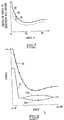
- the curve 41 is split during part of the opening and closing cycle of the valve, the upper part 41a of the curve 41 corresponding to the opening of the valve and the lower part 41b to the closing.
- the measurement and calculation results can be presented not only as a function of the angle ⁇ defining the position of the valve but also as a function of time, a relation being able to be established between the angle ⁇ defining the position of the valve and the time during the operation of the valve.
Landscapes
- Engineering & Computer Science (AREA)
- General Engineering & Computer Science (AREA)
- Mechanical Engineering (AREA)
- Electrically Driven Valve-Operating Means (AREA)
- Lift Valve (AREA)
- Fluid-Driven Valves (AREA)
Claims (11)
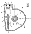
- Kontrollverfahren des Betriebsfähigkeitsbereichs eines Klappenventils (1) mit einer drehbar um eine Achse (5) in ein Ventilgehäuse (3) montierten Klappe (4) und Steuerungseinrichtungen (6, 7, 8) für das Verstellen der Klappe (4) zwischen einer geschlossenen Position und einer vollständig geöffneten Position des Ventils, einen Elektromotor (6), einen Servomotor (7) und ein Reduziergetriebe (8) umfassend, in Reihe angeordnet, um die Rotationsverstellung der Klappe (4) zu tätigen, wobei der Servomotor (7) einen regelbaren bzw. einstellbaren Drehmomentbegrenzer (18) umfasst, um den Motor (6) bei einem festgelegten, Dremomentbegrenzer-Auslösungsmoment genannten Ausgangsmoment des Servomotors (7) zu stoppen, wobei das Kontrollverfahren den Zweck hat, zu verifizieren, dass der Bereich zwischen einem Antriebsmoment der Klappe (4) und einem Auslösungsmoment des Drehmomentbegrenzers (18) für jede Position der Klappe (4) oder zu jedem Zeitpunkt des Betriebs des Ventils wenigstens gleich einem vorher festgelegten Schwellenwert ist,
dadurch gekennzeichnet, dass- man in einer ersten Anfangsphase die Klappe (4) von den Verstellungssteuerungseinrichtungen (6, 7, 8) trennt und man in einem Messstand wenigstens ein Moment, das Auslösungsmoment (CLdc) des Servomotors (7) und/oder das Ausgangsmoment des Reduziergetriebes (8) bei der Auslösung des Servomotors, in einer Vielzahl von Winkelverstellungspositionen der Klappe (4) misst, wobei die Steuerungseinrichtungen (6, 7, 8) durch den Elektromotor (6) angetrieben werden, und simultan die aktive Leistung des Motors (6) für eine Vielzahl von Steil- bzw. Regelwerten des Drehmomentbegrenzers (18) misst und man davon Transferfunktionen ableitet, um von der aktiven Leistung des Motors zu dem Antriebsmoment der Klappe (4) durch den Servomotor (7) und/oder das Reduziergetriebe (8) überzugehen,- man in einer zweiten Phase die Klappe (4) des Ventils (1) zwischen ihren geschlossenen und geöffneten Positionen verstellt, mit Hilfe der Steuerungseinrichtungen (6, 7, 8), angetrieben durch den Elektromotor (6), wobei sich das Ventil in einem normalen Betriebszustand befindet und der Drehmomentbegrenzer festgelegten Regelungsbedingungen unterliegt, man die aktive Leistung des Motors (6) misst und berechnet und daraus durch Berechnung - aufgrund der Transferfunktionen - Werte wenigstens eines Moments, des Ausgangsmoments des Servomotors und/oder des Ausgangsmoments des Reduziergetriebes, im Laufe der Verstellung der Klappe (4) ableitet, und- man die durch die Messung und die Berechnung erhaltenen Werte des Moments mit in der ersten Phase erhaltenen Werten vergleicht, die wenigstens einem Moment, dem Auslösungsmoment des Servomotors (7) und/oder dem Ausgangsmoment des Reduziergetriebes (8), bei der Auslösung des Servomotors (7) entsprechen. - Verfahren nach Anspruch 1, dadurch gekennzeichnet, dass der Motor (6) ein Drehstrommotor ist und man die aktive Leistung des Motors (6) aufgrund der Stromstärken (i1, i2, i3) und der Spannungen (u1, u2, u3) auf den drei Phasen des Motors bestimmt, die während des Betriebs des Motors gemessen werden.
- Verfahren nach einem der Ansprüche 1 und 2, dadurch gekennzeichnet, dass man zudem das Schließen und Öffnen des Ventils aufgrund von Signalen bestimmt, die von dem Klappenventil (1) zugeordneten Endbegrenzungsdetektoren stammen.
- Verfahren nach einem der Ansprüche 1 bis 3, dadurch gekennzeichnet, dass man in der ersten Phase des Verfahrens eine Transferfunktion (F) bestimmt, die ermöglicht; von der aktiven Leistung (P1) des Elektromotors (6) zu dem Ausgangsmoment des Servomotors (7) überzugehen.
- Verfahren nach einem der Ansprüche 1 bis 4, dadurch gekennzeichnet, dass man in der ersten Phase des Verfahrens eine Transferfunktion (Fα) bestimmt, die ermöglicht, von der aktiven Leistung (P1) des Elektromotors (6) zu dem Ausgangsmoment des Reduziergetriebes überzugehen, das für eine Vielzahl von Positionen der Klappe (4) des Ventils (1) zwischen ihrer geschlossenen Position und ihrer geöffneten Position gleich dem Widerstandsmoment der Klappe (4) des Ventils (1) ist, wobei jede Position aus der Vielzahl von Positionen definiert wird durch einen für die Position der Klappe (4) des Ventils repräsentativen Winkel α oder durch eine bestimmte Zeit während der Verstellung der Klappe (4) des Ventils (1).
- Kontrollverfahren nach einem der Ansprüche 1 bis 5, wobei der Servomotor (7) eine Schnecke (14) umfasst, angetrieben durch den Elektromotor (6) mittels Zahnrändem (11, 12) und einer Antriebswelle (13), und die Schnecke an ihrem der Antriebswelle (13) entgegengesetzten Ende durch einen Stapel von Tellerfederscheiben (15) abgestützt wird und dabei ein Schneckenrad (20) in die Schnecke (14) eingreifen und eine Ausgangswelle (9) des Servomotors in Drehung versetzen kann, wenn der Tellerfederscheibenstapel (15) sich nicht in einem komprimierten Zustand befindet, und der Drehmomentbegrenzer (18) einen Betätigungsfinger (17) umfasst, der mit einem Teil (16) der Schnecke (14) kooperiert, um für einen Kompressionszustand des Tellerfederscheibenstapels (15) und ein Antriebsmoment der Schnecke (14), eingestellt durch einen Steilzeiger, einen Versorgungsunterbrechungsschalter des Elektromotors (6) auszulösen,
dadurch gekennzeichnet, dass man in einem ersten Schritt der ersten Phase verifiziert, dass es eine lineare Relation zwischen der Position des Stellzeigers des Drehmomentbegrenzers (18) und des Ausgangsmoments des Servomotors (7) bei der Auslösung des Drehmomentbegrenzers (18) gibt, indem man in dem Messstand das Ausgangsmoment des Servomotors (7) für verschiedene Positionen des Stellzeigers des Drehmomentbegrenzers (18) misst, mit Hilfe einer Bremse (32), gekuppelt mit der Ausgangswelle (9) des Servomotors (7). - Verfahren nach Anspruch 6, dadurch gekennzeichnet, dass man in dem ersten Schritt der ersten Phase des Verfahrens zudem den Proportionalitätskoeffizienten (k) zwischen der Ausgangsgeschwindigkeit des Motors (6) und der Ausgangsgeschwindigkeit des Servomotors (7) bestimmt, indem man in dem Messstand das Ausgangsmoment des Servomotors (7) und simultan die aktive Leistung (P1) des Motors (6) durch Messung der Ströme und Spannungen in den Phasen des Motors (6) misst:
- Verfahren nach einem der Ansprüche 6 und 7, dadurch gekennzeichnet, dass man in einem zweiten Schritt der ersten Phase in dem Messstand das Ausgangsmoment des mit dem durch den Elektromotor (6) angetriebenen Servomotor (7) gekuppelten Reduziergetriebes misst, indem man eine Bremse (32) des Messstands mit der Ausgangswelle des Reduziergetriebes kuppelt, dann misst und die aktive Leistung des Motors (6) berechnet, für eine Vielzahl von Winkelpositionen des Reduziergetriebes (8) zur Verstellung der Klappe (4) des Ventils (1), und man die durch das Reduziergetriebe (8) verursachten Verluste bestimmt aufgrund einer Kurve, die den theoretischen Wert des Ausgangsmoments des Reduziergetriebes liefert, erhalten aus der aktiven Leistung (P1) des Motors (6) in Abhängigkeit von der Stellung der Klappe (4) des Ventils (1) und einer Kurve, die repräsentativ ist für den realen Wert des durch den Messstand an der Ausgangswelle des Reduziergetriebes gemessenen Moments.
- Verfahren nach Anspruch 8, dadurch gekennzeichnet, dass das Reduziergetriebe (8) ein nichtlineares Schnecken- bzw. Schraubengetnebe ist.
- Verfahren nach einem der Ansprüche 6 bis 9, dadurch gekennzeichnet, dass man den Betriebsfähigkeitsbereich des Servomotors (7) des Klappenventils (1) bestimmt, indem man bei dem Klappenventil unter realen Betriebsbedingungen des Ventils die aktive Leistung (P1) des Elektromotors (6) durch Messung der Stromstärke und der Spannung in den Phasen des Motors und durch Berechnung bestimmt, man das maximale Ausgangsmoment (Cmax) des Servomotors während eines dem Maximalwert (P1max) der aktiven Leistung des Motors (6) entsprechenden Betriebszyklus des Klappenventils (1) bestimmt, mittels einer in der ersten Phase des Verfahrens bestimmten Transferfunktion (F), und man den Bereich

berechnet aufgrund des während der ersten Phase des Verfahrens bestimmten Auslösungsmoments (CLdC) des Servomotors und des durch die Messung und die Berechnung der aktiven Leistung des Motors (6) bestimmten Maximalmoments (Cmax). - Verfahren nach einem der Ansprüche 6 bis 10, dadurch gekennzeichnet, dass man in einem zweiten Schritt der zweiten Phase des Verfahrens während eines Betriebszyklus des Klappenventils (1) die aktive Leistung (P1) des Elektromotors (6) misst und berechnet, man das Ausgangsmoment des Reduziergetriebes aufgrund der aktiven Leistung (P1) des Elektromotors (6) und insbesondere das maximale Moment (Cm) am Ausgang des Reduziergetriebes (8), das dem vorhergehend bestimmten maximalen Moment (Cmax) am Ausgang des Servomotors entspricht, berechnet und man daraus den Betriebsbereitschaftsbereich für die Position (αm) einer Klappe (4) des Ventils (1) ableitet, der am Ausgang des Reduziergetriebes das maximale Moment (Cmax) liefert, indem man den Abstand des Moments (Cm) am Ausgang des Reduziergetriebes in Bezug auf eine Kurve (40) misst, die das Ausgangsmoment des Reduziergetriebes (8) liefert, das dem Auslösungsmoment (CLdC) des Servomotors entspricht.
Applications Claiming Priority (2)
| Application Number | Priority Date | Filing Date | Title |
|---|---|---|---|
| FR9914371 | 1999-11-16 | ||
| FR9914371A FR2801102B1 (fr) | 1999-11-16 | 1999-11-16 | Procede de controle de la marge d'operabilite d'une vanne a papillon |
Publications (2)
| Publication Number | Publication Date |
|---|---|
| EP1102052A1 EP1102052A1 (de) | 2001-05-23 |
| EP1102052B1 true EP1102052B1 (de) | 2006-03-15 |
Family
ID=9552154
Family Applications (1)
| Application Number | Title | Priority Date | Filing Date |
|---|---|---|---|
| EP00403120A Expired - Lifetime EP1102052B1 (de) | 1999-11-16 | 2000-11-09 | Verfahren zur Steuerung eines Klappenventils |
Country Status (5)
| Country | Link |
|---|---|
| EP (1) | EP1102052B1 (de) |
| AT (1) | ATE320595T1 (de) |
| DE (1) | DE60026683T2 (de) |
| ES (1) | ES2255959T3 (de) |
| FR (1) | FR2801102B1 (de) |
Cited By (1)
| Publication number | Priority date | Publication date | Assignee | Title |
|---|---|---|---|---|
| CN117646198A (zh) * | 2024-01-30 | 2024-03-05 | 浙江大学 | 一种原子级精度的cvd设备压力自动控制方法及系统 |
Families Citing this family (6)
| Publication number | Priority date | Publication date | Assignee | Title |
|---|---|---|---|---|
| FR2827674B1 (fr) * | 2001-07-20 | 2003-10-03 | Chpolansky Ets | Procede et appareillage pour tester une soupape avec une mise en liquide,sans ouverture prealable de son obturateur |
| US10094485B2 (en) | 2008-07-18 | 2018-10-09 | Flowserve Management Company | Variable-speed actuator |
| MX346650B (es) | 2008-07-18 | 2017-03-28 | Flowserve Man Co | Accionador de velocidad variable. |
| IL227323A (en) * | 2013-07-04 | 2016-06-30 | Israel Radomsky | Wireless monitoring system and fault forecasting in linear valves |
| DE202018105168U1 (de) * | 2018-09-10 | 2019-12-12 | Feldbinder Spezialfahrzeugwerke Gmbh | Auslaufeinrichtung mit einem elektromechanischen Antrieb |
| CN111710541A (zh) * | 2020-06-24 | 2020-09-25 | 湖南长高高压开关集团股份公司 | 一种多功能伺服变速器以及高压隔离开关 |
Family Cites Families (4)
| Publication number | Priority date | Publication date | Assignee | Title |
|---|---|---|---|---|
| US4735101A (en) * | 1985-06-06 | 1988-04-05 | Charbonneau & Godfrey Associates | Motor operated valve analysis and testing system with monitoring of spring pack movement through torque switch post |
| US4816987A (en) * | 1985-06-28 | 1989-03-28 | Electric Power Research Institute, Inc. | Microprocessor-based control and diagnostic system for motor operated valves |
| US5396167A (en) * | 1993-06-03 | 1995-03-07 | Liberty Technologies, Inc. | Method for remotely determining operability of motor operated valves |
| DE19615176A1 (de) * | 1995-03-31 | 1997-10-23 | Istec Gmbh | Verfahren zur Überwachung und zum Betrieb von insbesondere motorgetriebenen Armaturen |
-
1999
- 1999-11-16 FR FR9914371A patent/FR2801102B1/fr not_active Expired - Fee Related
-
2000
- 2000-11-09 AT AT00403120T patent/ATE320595T1/de not_active IP Right Cessation
- 2000-11-09 EP EP00403120A patent/EP1102052B1/de not_active Expired - Lifetime
- 2000-11-09 ES ES00403120T patent/ES2255959T3/es not_active Expired - Lifetime
- 2000-11-09 DE DE60026683T patent/DE60026683T2/de not_active Expired - Fee Related
Cited By (2)
| Publication number | Priority date | Publication date | Assignee | Title |
|---|---|---|---|---|
| CN117646198A (zh) * | 2024-01-30 | 2024-03-05 | 浙江大学 | 一种原子级精度的cvd设备压力自动控制方法及系统 |
| CN117646198B (zh) * | 2024-01-30 | 2024-04-23 | 浙江大学 | 一种原子级精度的cvd设备压力自动控制方法及系统 |
Also Published As
| Publication number | Publication date |
|---|---|
| DE60026683D1 (de) | 2006-05-11 |
| FR2801102B1 (fr) | 2002-02-01 |
| ATE320595T1 (de) | 2006-04-15 |
| DE60026683T2 (de) | 2006-08-24 |
| FR2801102A1 (fr) | 2001-05-18 |
| ES2255959T3 (es) | 2006-07-16 |
| EP1102052A1 (de) | 2001-05-23 |
Similar Documents
| Publication | Publication Date | Title |
|---|---|---|
| EP1102052B1 (de) | Verfahren zur Steuerung eines Klappenventils | |
| EP0223713B1 (de) | Verfahren zum Anziehen und/oder Lösen von Bolzen und Vorrichtung dafür | |
| EP1958816B1 (de) | Verfahren und Vorrichtung zur Betätigung eines Sitzes | |
| BE1006830A3 (fr) | Procede de detection de la position d'ouverture relative de la vanne d'eau chaude et d'eau froide, a actionnement electrique, d'une batterie de melange sanitaire. | |
| FR2915293A1 (fr) | Dispositif de securite pour un detendeur de gaz et detendeur de gaz comportant un tel dispositif | |
| EP0524589A2 (de) | System und Verfahren zum Ermitteln des Ausgangsdrehmoments von motorbetriebenen Ventilstelleinrichtungen | |
| EP1906424A1 (de) | Vorrichtung zur Steuerung des Betriebs eines Dichtemessers für ein elektrisches Gerät mit Mittel- und Hochspannung und Verfahren zur Steuerung des Betriebs eines Dichtemessers | |
| EP1561087B1 (de) | Flüssigkeitsmenge-überwachungssystem | |
| CA3037781A1 (fr) | Procede d'engagement de deux elements engrenage et dispositif d'entrainement mettant en oeuvre un tel procede | |
| BE1007527A3 (fr) | Procede et dispositif de commande d'un verin a double effet actionne par un fluide sous pression. | |
| FR3037607A1 (fr) | Systeme d'entrainement d'ouvrant | |
| EP3546792A1 (de) | Verbindungsverfahren von zwei verzahnungselementen und antriebsvorrichtung, bei der dieses verfahren angewandt wird | |
| FR3014616A1 (fr) | Procede de regulation d'une commande d'un actionneur electrique de wastegate par mesure du courant traversant l'actionneur electrique | |
| EP2434352A1 (de) | Messgerät für Drehmoment und/oder Kraft | |
| WO2013093290A1 (fr) | Doseur deux voies avec un moteur unique agissant dans un seul sens | |
| CA3019864C (fr) | Mecanisme d'entrainement d'absorbants de controle de reacteur nucleaire, procede de surveillance et reacteur nucleaire correspondants | |
| EP0737831B1 (de) | Lagergehäuse eines Ventils | |
| EP1025380B1 (de) | Verfahren und vorrichtung zur regelung eines pneumatisch betätigten ventils | |
| EP3750170B1 (de) | Integrierte kernreaktorarchitektur zur begrenzung der belastung der integrierten mechanismen | |
| EP3482066A1 (de) | Verfahren zur optimierung der einstellung der anspritzung mindestens einer hydraulischen turbine | |
| FR2836206A1 (fr) | Dispositif de protection d'une installation de distribution d'eau raccordee a un reseau de distribution | |
| FR2834085A1 (fr) | Procede de commande et de controle d'un dispositif de regulation et dispositif correspondant | |
| WO2007080493A1 (fr) | Procede d'apprentissage d'une unite de commande de l'alimentation electrique d'un moteur | |
| EP0667471A1 (de) | Ventil zum Absperren eines Fluidkreislaufes im Falle eines Brandes | |
| FR2647177A1 (fr) | Electrovanne pour l'ecoulement de fluides |
Legal Events
| Date | Code | Title | Description |
|---|---|---|---|
| PUAI | Public reference made under article 153(3) epc to a published international application that has entered the european phase |
Free format text: ORIGINAL CODE: 0009012 |
|
| 17P | Request for examination filed |
Effective date: 20010310 |
|
| AK | Designated contracting states |
Kind code of ref document: A1 Designated state(s): AT BE CH CY DE DK ES FI FR GB GR IE IT LI LU MC NL PT SE TR |
|
| AX | Request for extension of the european patent |
Free format text: AL;LT;LV;MK;RO;SI |
|
| AKX | Designation fees paid |
Free format text: AT BE CH CY DE DK ES FI FR GB GR IE IT LI LU MC NL PT SE TR |
|
| GRAP | Despatch of communication of intention to grant a patent |
Free format text: ORIGINAL CODE: EPIDOSNIGR1 |
|
| GRAS | Grant fee paid |
Free format text: ORIGINAL CODE: EPIDOSNIGR3 |
|
| GRAA | (expected) grant |
Free format text: ORIGINAL CODE: 0009210 |
|
| AK | Designated contracting states |
Kind code of ref document: B1 Designated state(s): AT BE CH CY DE DK ES FI FR GB GR IE IT LI LU MC NL PT SE TR |
|
| PG25 | Lapsed in a contracting state [announced via postgrant information from national office to epo] |
Ref country code: IT Free format text: LAPSE BECAUSE OF FAILURE TO SUBMIT A TRANSLATION OF THE DESCRIPTION OR TO PAY THE FEE WITHIN THE PRESCRIBED TIME-LIMIT;WARNING: LAPSES OF ITALIAN PATENTS WITH EFFECTIVE DATE BEFORE 2007 MAY HAVE OCCURRED AT ANY TIME BEFORE 2007. THE CORRECT EFFECTIVE DATE MAY BE DIFFERENT FROM THE ONE RECORDED. Effective date: 20060315 Ref country code: IE Free format text: LAPSE BECAUSE OF FAILURE TO SUBMIT A TRANSLATION OF THE DESCRIPTION OR TO PAY THE FEE WITHIN THE PRESCRIBED TIME-LIMIT Effective date: 20060315 Ref country code: NL Free format text: LAPSE BECAUSE OF FAILURE TO SUBMIT A TRANSLATION OF THE DESCRIPTION OR TO PAY THE FEE WITHIN THE PRESCRIBED TIME-LIMIT Effective date: 20060315 Ref country code: AT Free format text: LAPSE BECAUSE OF FAILURE TO SUBMIT A TRANSLATION OF THE DESCRIPTION OR TO PAY THE FEE WITHIN THE PRESCRIBED TIME-LIMIT Effective date: 20060315 |
|
| REG | Reference to a national code |
Ref country code: CH Ref legal event code: EP Ref country code: GB Ref legal event code: FG4D Free format text: NOT ENGLISH |
|
| REG | Reference to a national code |
Ref country code: IE Ref legal event code: FG4D Free format text: LANGUAGE OF EP DOCUMENT: FRENCH |
|
| REF | Corresponds to: |
Ref document number: 60026683 Country of ref document: DE Date of ref document: 20060511 Kind code of ref document: P |
|
| REG | Reference to a national code |
Ref country code: SE Ref legal event code: TRGR |
|
| PG25 | Lapsed in a contracting state [announced via postgrant information from national office to epo] |
Ref country code: DK Free format text: LAPSE BECAUSE OF FAILURE TO SUBMIT A TRANSLATION OF THE DESCRIPTION OR TO PAY THE FEE WITHIN THE PRESCRIBED TIME-LIMIT Effective date: 20060615 |
|
| REG | Reference to a national code |
Ref country code: ES Ref legal event code: FG2A Ref document number: 2255959 Country of ref document: ES Kind code of ref document: T3 |
|
| GBT | Gb: translation of ep patent filed (gb section 77(6)(a)/1977) |
Effective date: 20060628 |
|
| PG25 | Lapsed in a contracting state [announced via postgrant information from national office to epo] |
Ref country code: PT Free format text: LAPSE BECAUSE OF FAILURE TO SUBMIT A TRANSLATION OF THE DESCRIPTION OR TO PAY THE FEE WITHIN THE PRESCRIBED TIME-LIMIT Effective date: 20060816 |
|
| NLV1 | Nl: lapsed or annulled due to failure to fulfill the requirements of art. 29p and 29m of the patents act | ||
| REG | Reference to a national code |
Ref country code: IE Ref legal event code: FD4D |
|
| PG25 | Lapsed in a contracting state [announced via postgrant information from national office to epo] |
Ref country code: MC Free format text: LAPSE BECAUSE OF NON-PAYMENT OF DUE FEES Effective date: 20061130 |
|
| PLBE | No opposition filed within time limit |
Free format text: ORIGINAL CODE: 0009261 |
|
| STAA | Information on the status of an ep patent application or granted ep patent |
Free format text: STATUS: NO OPPOSITION FILED WITHIN TIME LIMIT |
|
| 26N | No opposition filed |
Effective date: 20061218 |
|
| REG | Reference to a national code |
Ref country code: FR Ref legal event code: CA Ref country code: FR Ref legal event code: CD |
|
| PG25 | Lapsed in a contracting state [announced via postgrant information from national office to epo] |
Ref country code: GR Free format text: LAPSE BECAUSE OF FAILURE TO SUBMIT A TRANSLATION OF THE DESCRIPTION OR TO PAY THE FEE WITHIN THE PRESCRIBED TIME-LIMIT Effective date: 20060616 |
|
| PG25 | Lapsed in a contracting state [announced via postgrant information from national office to epo] |
Ref country code: LU Free format text: LAPSE BECAUSE OF NON-PAYMENT OF DUE FEES Effective date: 20061109 Ref country code: TR Free format text: LAPSE BECAUSE OF FAILURE TO SUBMIT A TRANSLATION OF THE DESCRIPTION OR TO PAY THE FEE WITHIN THE PRESCRIBED TIME-LIMIT Effective date: 20060315 |
|
| PG25 | Lapsed in a contracting state [announced via postgrant information from national office to epo] |
Ref country code: CY Free format text: LAPSE BECAUSE OF FAILURE TO SUBMIT A TRANSLATION OF THE DESCRIPTION OR TO PAY THE FEE WITHIN THE PRESCRIBED TIME-LIMIT Effective date: 20060315 |
|
| PGFP | Annual fee paid to national office [announced via postgrant information from national office to epo] |
Ref country code: CH Payment date: 20081125 Year of fee payment: 9 |
|
| PGFP | Annual fee paid to national office [announced via postgrant information from national office to epo] |
Ref country code: ES Payment date: 20081126 Year of fee payment: 9 Ref country code: FI Payment date: 20081128 Year of fee payment: 9 |
|
| PGFP | Annual fee paid to national office [announced via postgrant information from national office to epo] |
Ref country code: SE Payment date: 20081128 Year of fee payment: 9 |
|
| PGFP | Annual fee paid to national office [announced via postgrant information from national office to epo] |
Ref country code: FR Payment date: 20081117 Year of fee payment: 9 |
|
| PGFP | Annual fee paid to national office [announced via postgrant information from national office to epo] |
Ref country code: DE Payment date: 20081223 Year of fee payment: 9 |
|
| PGFP | Annual fee paid to national office [announced via postgrant information from national office to epo] |
Ref country code: GB Payment date: 20081128 Year of fee payment: 9 |
|
| PGFP | Annual fee paid to national office [announced via postgrant information from national office to epo] |
Ref country code: BE Payment date: 20090128 Year of fee payment: 9 |
|
| BERE | Be: lapsed |
Owner name: FRAMATOME ANP Effective date: 20091130 |
|
| EUG | Se: european patent has lapsed | ||
| REG | Reference to a national code |
Ref country code: CH Ref legal event code: PL |
|
| GBPC | Gb: european patent ceased through non-payment of renewal fee |
Effective date: 20091109 |
|
| REG | Reference to a national code |
Ref country code: FR Ref legal event code: ST Effective date: 20100730 |
|
| PG25 | Lapsed in a contracting state [announced via postgrant information from national office to epo] |
Ref country code: FI Free format text: LAPSE BECAUSE OF NON-PAYMENT OF DUE FEES Effective date: 20091109 |
|
| PG25 | Lapsed in a contracting state [announced via postgrant information from national office to epo] |
Ref country code: BE Free format text: LAPSE BECAUSE OF NON-PAYMENT OF DUE FEES Effective date: 20091130 Ref country code: LI Free format text: LAPSE BECAUSE OF NON-PAYMENT OF DUE FEES Effective date: 20091130 Ref country code: FR Free format text: LAPSE BECAUSE OF NON-PAYMENT OF DUE FEES Effective date: 20091130 Ref country code: CH Free format text: LAPSE BECAUSE OF NON-PAYMENT OF DUE FEES Effective date: 20091130 |
|
| PG25 | Lapsed in a contracting state [announced via postgrant information from national office to epo] |
Ref country code: DE Free format text: LAPSE BECAUSE OF NON-PAYMENT OF DUE FEES Effective date: 20100601 |
|
| PG25 | Lapsed in a contracting state [announced via postgrant information from national office to epo] |
Ref country code: GB Free format text: LAPSE BECAUSE OF NON-PAYMENT OF DUE FEES Effective date: 20091109 |
|
| REG | Reference to a national code |
Ref country code: ES Ref legal event code: FD2A Effective date: 20110323 |
|
| PG25 | Lapsed in a contracting state [announced via postgrant information from national office to epo] |
Ref country code: SE Free format text: LAPSE BECAUSE OF NON-PAYMENT OF DUE FEES Effective date: 20091110 |
|
| PG25 | Lapsed in a contracting state [announced via postgrant information from national office to epo] |
Ref country code: ES Free format text: LAPSE BECAUSE OF NON-PAYMENT OF DUE FEES Effective date: 20110310 |
|
| PG25 | Lapsed in a contracting state [announced via postgrant information from national office to epo] |
Ref country code: ES Free format text: LAPSE BECAUSE OF NON-PAYMENT OF DUE FEES Effective date: 20091110 |