EP1102076A2 - Imagerie par résonance magnétique - Google Patents
Imagerie par résonance magnétique Download PDFInfo
- Publication number
- EP1102076A2 EP1102076A2 EP00310108A EP00310108A EP1102076A2 EP 1102076 A2 EP1102076 A2 EP 1102076A2 EP 00310108 A EP00310108 A EP 00310108A EP 00310108 A EP00310108 A EP 00310108A EP 1102076 A2 EP1102076 A2 EP 1102076A2
- Authority
- EP
- European Patent Office
- Prior art keywords
- collected
- sensitivity information
- sensitivity
- encode
- image
- Prior art date
- Legal status (The legal status is an assumption and is not a legal conclusion. Google has not performed a legal analysis and makes no representation as to the accuracy of the status listed.)
- Ceased
Links
Images


Classifications
-
- G—PHYSICS
- G01—MEASURING; TESTING
- G01R—MEASURING ELECTRIC VARIABLES; MEASURING MAGNETIC VARIABLES
- G01R33/00—Arrangements or instruments for measuring magnetic variables
- G01R33/20—Arrangements or instruments for measuring magnetic variables involving magnetic resonance
- G01R33/44—Arrangements or instruments for measuring magnetic variables involving magnetic resonance using nuclear magnetic resonance [NMR]
- G01R33/48—NMR imaging systems
- G01R33/54—Signal processing systems, e.g. using pulse sequences ; Generation or control of pulse sequences; Operator console
-
- G—PHYSICS
- G01—MEASURING; TESTING
- G01R—MEASURING ELECTRIC VARIABLES; MEASURING MAGNETIC VARIABLES
- G01R33/00—Arrangements or instruments for measuring magnetic variables
- G01R33/20—Arrangements or instruments for measuring magnetic variables involving magnetic resonance
- G01R33/44—Arrangements or instruments for measuring magnetic variables involving magnetic resonance using nuclear magnetic resonance [NMR]
- G01R33/48—NMR imaging systems
- G01R33/54—Signal processing systems, e.g. using pulse sequences ; Generation or control of pulse sequences; Operator console
- G01R33/56—Image enhancement or correction, e.g. subtraction or averaging techniques, e.g. improvement of signal-to-noise ratio and resolution
- G01R33/561—Image enhancement or correction, e.g. subtraction or averaging techniques, e.g. improvement of signal-to-noise ratio and resolution by reduction of the scanning time, i.e. fast acquiring systems, e.g. using echo-planar pulse sequences
- G01R33/5611—Parallel magnetic resonance imaging, e.g. sensitivity encoding [SENSE], simultaneous acquisition of spatial harmonics [SMASH], unaliasing by Fourier encoding of the overlaps using the temporal dimension [UNFOLD], k-t-broad-use linear acquisition speed-up technique [k-t-BLAST], k-t-SENSE
Definitions
- This invention relates to magnetic resonance (MR) imaging.
- the invention is particularly concerned with reduction in the time needed to collect data for imaging a region of interest of a patient.
- a malignant tumour may require a greater supply of blood and could show up in this way.
- FIG. 1 A prior art magnetic resonance imaging apparatus is shown in Figure 1.
- a patient 1 (shown in section) is slid axially into the bore 2 of a superconducting magnet 3, and the main magnetic field is set up along the axis of the bore, termed by convention the Z-direction.
- Magnetic field gradients are set up, for example, in the Z-direction, to confine the excitation of magnetic resonant (MR) active nuclei (typically hydrogen protons in water and fat tissue) to a particular slice in the Z-direction e.g. that illustrated in Figure 1 and, in the horizontal X and the vertical Y directions as seen in Figure 1, to encode the resonant MR nuclei in the plane of the slice.
- An r.f transmit coil (not shown) applies an excitation pulse to excite the protons to resonance, and a pair of r.f. receive coils 4, 5 pick up relaxation signals emitted by the disturbed protons.
- the signals are detected in the presence of a magnetic field gradient, termed a read-out gradient, to enable different positions of relaxing nuclei to correspond to different precession frequencies of those nuclei about the direction of the main magnetic field due to the influence of the gradient.
- the data is digitised, and so for each r.f. excitation pulse, a series of digital data points are collected, and these are mapped into a spatial frequency domain known as K-space ( Figure 2).
- Each r.f. pulse permits at least one column of digital data points to be collected.
- a magnetic field gradient in the X-direction is turned on and off This is done for a series of magnitudes of magnetic field gradients in the X-direction, one r.f. pulse typically corresponding to a different magnitude of gradient in the X-direction.
- the field of view imaged by the magnetic resonance imaging apparatus depends on the spacing of the data points in the phase-encode and read-out directions, and the resolution of the image depends on how far the points extend in each direction e.g. how large the maximum phase-encode gradient is.
- the signals received from the r.f. receiver coils 4, 5 are subject to a two dimensional fast Fourier Transform in Fourier Transform processors 6, 7, to produce pixelated images which are stored in image memories 8, 9.
- FIG. 3 A slice image is shown in Figure 3.
- Figure 3 implies that the spacing of data points in the phase-encode gradient direction is sufficient to image the whole of the slice shown in Figure 1.
- One technique used to reduce the data collection time is to cut out, say, half the phase-encode steps e.g. by keeping the same maximum phase-encode gradient but omitting every other column of data. This would then halve the data collection time.
- the response of coil 4 to MR signals from point P 1 is perhaps greater than its response to MR signals emanating from point P 2 , and the position is perhaps the other way round with regard to the coil 5.
- Knowledge of the relative sensitivities of the coils 4, 5 can be used in the processor 10 to unfold the aliased image of Figure 4 into an image having the pattern of Figure 3, although with a lower signal-to-noise ratio because only half the data has been collected.
- coil 4 receives MR signals from both points P 1 and P 2 , and the combined intensity of the resulting pixel stored in image memory 8 (C 1 ) depends on the sensitivity of the coil 4 to point P 1 (S 11 ) and the sensitivity of the coil 4 to point P 2 (S 12 ).
- the image memory 9 also has an intensity stored (C 2 ) corresponding to points P land P 2 which depends on the sensitivity of coil 5 to P 1 (S 21 ) and on its sensitivity to P 2 (S 22 ).
- C 1 S 11 P 1 +S 12 P 2
- C 2 S 21 P 1 + S 22 P 2
- (C) (S).(P) where (C), (S) and (P) are matrices.
- the intensity corresponding to each pixel P 1 and P 2 separately can be calculated in processor 10, for each pair of points of the image which are mapped onto the same pixel in the aliased image.
- the aliased image can then be unfolded and viewed in full on display 11.
- the paper referred to suggests collecting the sensitivity data using a third receive coil, in the form of a body coil, which has a uniform sensitivity over each part of the object.
- the sensitivity profile for the coil 4 could be as shown in Figure 6 and that for the body coil as shown in Figure 7.
- Figure 8 shows the division of one by the other and the presence of noise.
- the paper referred to proposes to divide the response of one coil 4 ( Figure 9) by the response of the other coil 5 ( Figure 10) and to dispense with the body coil altogether, for each line of the image. This is possible because it turns out that the (S) matrix terms only require this ratio to suppress the weighting effect of the object and the correction for the relative sensitivities produced by the two coils.
- the invention provides apparatus for magnetic resonance imaging, comprising means for creating magnetic field gradients in a phase-encode direction for spatially encoding excited MR active nuclei in a region of interest of a patient, means for receiving r.f. signals from the excited MR active nuclei, means for processing the spatially encoded r.f. receive signals to produce a spatial representation of the region of interest, the magnetic field gradient means being arranged to create a number of phase-encode gradients corresponding to a smaller field of view than the region of interest, the r.f. receive means including a pair of receive coils and processing means arranged to use the r.f. signals received from each coil together with sensitivity information for the coils to produce an unfolded version of the aliased data corresponding to the reduced field of view, wherein the sensitivity information used is arranged to be collected at reduced resolution compared to that at which the image is collected.
- the invention also provides a method of magnetic resonance imaging, comprising creating magnetic field gradients in a phase-encode direction to spatially encode excited MR active nuclei in a region of interest of a patient, receiving r.f. signals from the excited MR active nuclei, processing the spatially encoded r.f. receive signals to produce a spatial representation of the region of interest, the number of phase-encode gradients being created corresponding to a smaller field of view than the region of interest, a pair of r.f. receive coils receiving the r.f. signals, and the processing using the r.f. signals received from each coil together with sensitivity information for the coils to produce an unfolded version of the aliased data corresponding to the reduced field of view, wherein the sensitivity information used is collected at reduced resolution compared to that at which the image is collected.
- the sensitivity information may be collected by ratioing each of the receive coils with a body coil, or by ratioing the sensitivities of the two r.f. receive coils themselves. These may be of the loop and butterfly type as claimed in our co-pending British patent application no. 9926923.5, but could be a pair of loops or any other types. Further, further pairs of loops may be provided.
- reference data is collected at reduced resolution compared to that used during imaging.
- the reference data is of course collected at full field of view. Lower maximum values of phase-encode gradient are used.
- the effect of lower resolution in the reference data, used to calibrate the sensitivity of the coils 4, 5 is to reduce noise in the reference data.
- the reference data which is stored in memory 12, is used in the SENSE method to unfold the aliased data of Figure 4. Because the noise is reduced in the reference data, the signal-to-noise of the target unfolded SENSE data, is increased.
- One pair of coils 4, 5 may be used.
- a loop, butterfly combination as claimed in our co-pending British patent application no. 9926923.5 may be used.
- More than one pair of coils may be used.
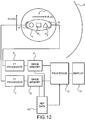
- the reference data may be produced using a body coil as in Figures 6 to 8, or a body coil may be omitted, as in Figures 9 to 11.
- DMRM dynamic enhanced MR mammography
- Sensitivity encoding SENSE requires an array coil with coil elements that have spatially distinct sensitivity profiles over the region of interest.
- a 4 channel receive only array coil with two pairs of nominally orthogonal coils is used, each pair providing approximately uniform sensitivity over one breast. Only one pair of coils is shown in Figure 12.
- the dynamic examination consisted of full resolution volume scans with the phase encoded, left-right FoV reduced by two as explained in our co-pending British patent application no. 9926923.5. The resulting degeneracy is unfolded using sensitivity data from the coils.
- sensitivity data is acquired with the subject in situ. This data is contaminated by a dependence on tissue signals, which can be removed by normalising using anatomical images that are assumed to be free of sensitivity variations.
- the approach used here uses the relative sensitivities of the coils in the array. In either case the sensitivity data requires a high signal-to-noise ratio (SNR) to avoid compromising the SNR of the final data. Filtering the sensitivity data can increase SNR.
- SNR signal-to-noise ratio
- all data was acquired on a 0.5T Picker Apollo scanner (Cleveland, OH) using a 3D gradient echo sequence (TR/TE 10/3.75) to image a region 30x3ox18cm 3 .
- Coil sensitivity information was obtained with a matrix of 64x32x50, 10NEX and was zero filled to 256x256x50 prior to reconstruction.
- Dynamic data was acquired in 10 frames, each with half left-right FoV and a rectangular matrix of 256x128x50, 1NEX (40s per frame). The data were reconstructed and unfolded onto a full FoV, 256x256x50 matrix. Unfolding was performed pair wise for the two symmetrical left-right coil combinations. The final images were then added in quadrature. Image manipulation employed IDL (Research Systems, Colorado).
- the method was tested on phantoms, two normal volunteers without contrast, and one normal volunteer with contrast.
- Reference data acquired at full resolution with a single average and reduced resolution with multiple averages were collected and compared for SENSE processing.
- Reduced FoV SENSE processed data and full FoV standard images were obtained using the same acquisition. Images were assessed for anatomical detail, artefacts and sensitivity to contrast uptake.
- an application of SENSE increases the temporal resolution of DMRM by a factor of two.
- the method has been shown to have sufficient sensitivity and immunity from artefacts for detecting enhancement in normal tissue with a temporal resolution well suited for pathological uptake
- magnet has been described as a superconducting magnet, it could be a resistive magnet, and need not be of the annular configuration but could be an open C or H configuration, and indeed, permanent magnets could be used.
Landscapes
- Physics & Mathematics (AREA)
- Engineering & Computer Science (AREA)
- Signal Processing (AREA)
- High Energy & Nuclear Physics (AREA)
- Condensed Matter Physics & Semiconductors (AREA)
- General Physics & Mathematics (AREA)
- Health & Medical Sciences (AREA)
- General Health & Medical Sciences (AREA)
- Nuclear Medicine, Radiotherapy & Molecular Imaging (AREA)
- Radiology & Medical Imaging (AREA)
- Magnetic Resonance Imaging Apparatus (AREA)
Applications Claiming Priority (2)
| Application Number | Priority Date | Filing Date | Title |
|---|---|---|---|
| GBGB9926918.5A GB9926918D0 (en) | 1999-11-15 | 1999-11-15 | Magnetic resonance imaging |
| GB9926918 | 1999-11-15 |
Publications (2)
| Publication Number | Publication Date |
|---|---|
| EP1102076A2 true EP1102076A2 (fr) | 2001-05-23 |
| EP1102076A3 EP1102076A3 (fr) | 2002-10-02 |
Family
ID=10864490
Family Applications (1)
| Application Number | Title | Priority Date | Filing Date |
|---|---|---|---|
| EP00310108A Ceased EP1102076A3 (fr) | 1999-11-15 | 2000-11-14 | Imagerie par résonance magnétique |
Country Status (4)
| Country | Link |
|---|---|
| US (1) | US6396269B1 (fr) |
| EP (1) | EP1102076A3 (fr) |
| JP (1) | JP2001198108A (fr) |
| GB (1) | GB9926918D0 (fr) |
Cited By (8)
| Publication number | Priority date | Publication date | Assignee | Title |
|---|---|---|---|---|
| WO2002086528A1 (fr) * | 2001-04-20 | 2002-10-31 | Koninklijke Philips Electronics Nv | Combinaison de signaux provenant d'un ensemble d'antennes et appliquant l'estimation des profils de sensibilite d'antenne sur la base des signaux |
| WO2004048992A1 (fr) * | 2002-11-26 | 2004-06-10 | Koninklijke Philips Electronics N.V. | Methode de resonance magnetique |
| WO2004111672A1 (fr) * | 2003-06-19 | 2004-12-23 | Koninklijke Philips Electronics N.V. | Imagerie par resonance magnetique avec codage par facteurs de sensibilite dans la direction de lecture |
| US6836116B2 (en) | 2002-07-01 | 2004-12-28 | Ge Medical Systems Global Technology Company, Llc. | Sensitivity encoding magnetic resonance imaging method and system |
| US6950543B2 (en) | 2002-05-02 | 2005-09-27 | Ge Medical Systems Global Technology Company, Llc | Method and system for image reconstruction |
| US7224163B2 (en) | 2002-04-30 | 2007-05-29 | Hitachi Medical Corporation | Magnetic resonance imaging device |
| CN100563555C (zh) * | 2001-09-13 | 2009-12-02 | 株式会社日立医药 | 磁共振成像装置和磁共振成像用rf接收线圈装置 |
| EP2581756A1 (fr) * | 2011-10-11 | 2013-04-17 | Koninklijke Philips Electronics N.V. | Imagerie par RM utilisant l'acquisition de signaux parallèles |
Families Citing this family (24)
| Publication number | Priority date | Publication date | Assignee | Title |
|---|---|---|---|---|
| CA2319513C (fr) * | 1998-02-05 | 2007-05-29 | Mitsubishi International Gmbh | Procede de creation d'un repertoire d'adresses |
| GB2348005A (en) * | 1999-03-13 | 2000-09-20 | Marconi Electronic Syst Ltd | NMR apparatus with additional RF receive coil to reduce aliasing |
| US6611143B2 (en) * | 2000-03-14 | 2003-08-26 | Kabushiki Kaisha Toshiba | MRI apparatus generating odd and/or even echo images with sensitivity distribution of coils |
| US6946836B2 (en) * | 2000-04-25 | 2005-09-20 | Kabushiki Kaisha Toshiba | Magnetic resonance imaging involving movement of patient's couch |
| WO2002042791A1 (fr) * | 2000-11-24 | 2002-05-30 | Koninklijke Philips Electronics N.V. | Procede permettant d'obtenir des images irm par sous-echantillonnage dans un appareil irm a champ vertical |
| WO2002056767A1 (fr) * | 2001-01-19 | 2002-07-25 | Kabushiki Kaisha Toshiba | Imagerie parallele par resonance magnetique utilisant une carte de sensibilite de bobine haute precision |
| US6841998B1 (en) * | 2001-04-06 | 2005-01-11 | Mark Griswold | Magnetic resonance imaging method and apparatus employing partial parallel acquisition, wherein each coil produces a complete k-space datasheet |
| DE10119660B4 (de) * | 2001-04-20 | 2006-01-05 | Siemens Ag | Verfahren zur schnellen Gewinnung eines Magnetresonanzbildes |
| GB2380549A (en) * | 2001-04-20 | 2003-04-09 | Marconi Medical Systems Uk Ltd | Magnetic Resonance Imaging |
| GB2374673A (en) * | 2001-04-20 | 2002-10-23 | Marconi Medical Systems Uk Ltd | Magnetic Resonance Imaging |
| GB2374672A (en) * | 2001-04-20 | 2002-10-23 | Marconi Medical Systems Uk Ltd | Magnetic Resonance Imaging |
| US6822450B2 (en) * | 2002-04-26 | 2004-11-23 | Ge Medical Systems Global Technology Company, Llc | Multiple channel, cardiac array for sensitivity encoding in magnetic resonance imaging |
| AU2003230109A1 (en) * | 2002-05-13 | 2003-11-11 | Koninklijke Philips Electronics N.V. | Magnetic resonance imaging method |
| US6833700B2 (en) * | 2002-09-13 | 2004-12-21 | General Electric Company | Method and apparatus for reconstruction of images in parallel MRI systems |
| DE10318682B4 (de) * | 2003-04-24 | 2011-12-29 | Peter M. Jakob | Beschleunigte Magnet-Resonanz-Bildgebung im Rahmen der parallelen Akquisition von MRT-Daten |
| US6876199B2 (en) * | 2003-05-30 | 2005-04-05 | General Electric Company | Method and system for accelerated imaging using parallel MRI |
| US7025883B1 (en) * | 2003-09-30 | 2006-04-11 | Ok Technologies, Llc | Autotrofic sulfur denitration chamber and calcium reactor |
| US6919722B2 (en) * | 2003-10-09 | 2005-07-19 | Ge Medical Systems Global Technology Company, Llc | Image quality improvement for SENSE with low signal regions |
| JP4786128B2 (ja) * | 2003-11-05 | 2011-10-05 | 株式会社東芝 | 磁気共鳴イメージング装置 |
| US7218106B2 (en) * | 2003-12-04 | 2007-05-15 | Kabushiki Kaisha Toshiba | MRI with automatic contour-controlled separation between RF coil and object being imaged |
| US7095229B2 (en) * | 2004-01-20 | 2006-08-22 | Siemens Corporate Research Inc. | Multicoil image analysis for magnetic resonance image segmentation, registration, and reconstruction |
| US7941204B1 (en) * | 2004-11-16 | 2011-05-10 | Yi Wang | Magnetic resonance imaging concepts |
| US8238634B1 (en) * | 2007-02-23 | 2012-08-07 | University Of Virginia Patent Foundation | Efficient off-resonance correction method and system for spiral imaging with improved accuracy |
| US8948534B2 (en) * | 2011-04-22 | 2015-02-03 | Kabushiki Kaisha Toshiba | MRI Gibbs' ringing filtering with edge-protection |
Family Cites Families (3)
| Publication number | Priority date | Publication date | Assignee | Title |
|---|---|---|---|---|
| DE59509825D1 (de) * | 1994-08-03 | 2001-12-20 | Philips Corp Intellectual Pty | MR-Verfahren zur Bestimmung der Kernmagnetisierungsverteilung mit einer Oberflächenspulen-Anordnung |
| CN1111746C (zh) | 1998-04-17 | 2003-06-18 | 皇家菲利浦电子有限公司 | 磁共振成象方法和装置 |
| US6242916B1 (en) * | 1999-11-17 | 2001-06-05 | General Electric Company | Partial fourier acquistion of MR data over a limited field of view and image reconstruction |
-
1999
- 1999-11-15 GB GBGB9926918.5A patent/GB9926918D0/en not_active Ceased
-
2000
- 2000-11-14 EP EP00310108A patent/EP1102076A3/fr not_active Ceased
- 2000-11-15 JP JP2000389583A patent/JP2001198108A/ja active Pending
- 2000-11-15 US US09/713,716 patent/US6396269B1/en not_active Expired - Fee Related
Non-Patent Citations (1)
| Title |
|---|
| PRUESSMANN K.P. ET AL: "Coil Sensitivity Encoding for Fast MRI", PROCEEDINGS OF THE INTERNATIONAL SOCIETY FOR MAGNETIC RESONANCE IN MEDICINE, 6TH ANNUAL MEETING, 1998, Sydney, pages 579 * |
Cited By (9)
| Publication number | Priority date | Publication date | Assignee | Title |
|---|---|---|---|---|
| WO2002086528A1 (fr) * | 2001-04-20 | 2002-10-31 | Koninklijke Philips Electronics Nv | Combinaison de signaux provenant d'un ensemble d'antennes et appliquant l'estimation des profils de sensibilite d'antenne sur la base des signaux |
| CN100563555C (zh) * | 2001-09-13 | 2009-12-02 | 株式会社日立医药 | 磁共振成像装置和磁共振成像用rf接收线圈装置 |
| US7224163B2 (en) | 2002-04-30 | 2007-05-29 | Hitachi Medical Corporation | Magnetic resonance imaging device |
| US6950543B2 (en) | 2002-05-02 | 2005-09-27 | Ge Medical Systems Global Technology Company, Llc | Method and system for image reconstruction |
| US6836116B2 (en) | 2002-07-01 | 2004-12-28 | Ge Medical Systems Global Technology Company, Llc. | Sensitivity encoding magnetic resonance imaging method and system |
| WO2004048992A1 (fr) * | 2002-11-26 | 2004-06-10 | Koninklijke Philips Electronics N.V. | Methode de resonance magnetique |
| WO2004111672A1 (fr) * | 2003-06-19 | 2004-12-23 | Koninklijke Philips Electronics N.V. | Imagerie par resonance magnetique avec codage par facteurs de sensibilite dans la direction de lecture |
| US7375524B2 (en) | 2003-06-19 | 2008-05-20 | Koninklijke Philips Electronics N.V. | Mr imaging with sensitivity encoding in the readout direction |
| EP2581756A1 (fr) * | 2011-10-11 | 2013-04-17 | Koninklijke Philips Electronics N.V. | Imagerie par RM utilisant l'acquisition de signaux parallèles |
Also Published As
| Publication number | Publication date |
|---|---|
| EP1102076A3 (fr) | 2002-10-02 |
| GB9926918D0 (en) | 2000-01-12 |
| JP2001198108A (ja) | 2001-07-24 |
| US6396269B1 (en) | 2002-05-28 |
Similar Documents
| Publication | Publication Date | Title |
|---|---|---|
| US6396269B1 (en) | Magnetic resonance imaging | |
| Barfuss et al. | In vivo magnetic resonance imaging and spectroscopy of humans with a 4 T whole‐body magnet | |
| Young et al. | The benefits of increasing spatial resolution as a means of reducing artifacts due to field inhomogeneities | |
| US5771893A (en) | Method and apparatus for nuclear magnetic resonance imaging of physiological function information | |
| US6380741B1 (en) | Magnetic resonance imaging | |
| US6876199B2 (en) | Method and system for accelerated imaging using parallel MRI | |
| RU2683605C1 (ru) | Параллельная мр-томография с картированием чувствительности с помощью рч-катушки | |
| US10156625B2 (en) | MR imaging with B1 mapping | |
| US12019134B2 (en) | MR electric properties tomography without contrast agent | |
| US10712419B2 (en) | Selective size imaging using filters via diffusion times | |
| Larkman et al. | An investigation into the use of sensitivity‐encoded techniques to increase temporal resolution in dynamic contrast‐enhanced breast imaging | |
| EP1567881A1 (fr) | Methode de resonance magnetique | |
| CN110246568A (zh) | 具有谱脂肪抑制的并行mr成像 | |
| US9316711B2 (en) | System and method for accelerated magnetic resonance imaging using spectral sensitivity | |
| US20030097058A1 (en) | Method and apparatus for magnetic resonance imaging with simultaneous measurement of two neighboring slices | |
| US11815582B2 (en) | Dual echo steady state MR imaging using bipolar diffusion gradients | |
| JP2022522240A5 (fr) | ||
| US11029379B2 (en) | Bridge member for a magnetic resonance examination system | |
| Larkman et al. | Increasing temporal resolution in dynamic Gd enhanced breast imaging using SENSE | |
| Gowland et al. | Reducing motion artifacts in in vivo magnetic resonance imaging measurements of relaxation times | |
| Huang et al. | Comparison of phase-encoded and sensitivity-encoded spectroscopic imaging | |
| Wald et al. | NAA‐weighted imaging of the human brain using a conventional readout gradient | |
| Nambu | 4895157 Magnetic resonance imaging system | |
| Pruessmann | Parallel Imaging | |
| van Gelderen et al. | A Simple B |
Legal Events
| Date | Code | Title | Description |
|---|---|---|---|
| PUAI | Public reference made under article 153(3) epc to a published international application that has entered the european phase |
Free format text: ORIGINAL CODE: 0009012 |
|
| AK | Designated contracting states |
Kind code of ref document: A2 Designated state(s): AT BE CH CY DE DK ES FI FR GB GR IE IT LI LU MC NL PT SE TR |
|
| AX | Request for extension of the european patent |
Free format text: AL;LT;LV;MK;RO;SI |
|
| PUAL | Search report despatched |
Free format text: ORIGINAL CODE: 0009013 |
|
| AK | Designated contracting states |
Kind code of ref document: A3 Designated state(s): AT BE CH CY DE DK ES FI FR GB GR IE IT LI LU MC NL PT SE TR |
|
| AX | Request for extension of the european patent |
Free format text: AL;LT;LV;MK;RO;SI |
|
| RAP1 | Party data changed (applicant data changed or rights of an application transferred) |
Owner name: MARCONI OPTICAL COMPONENTS LIMITED |
|
| 17P | Request for examination filed |
Effective date: 20030402 |
|
| AKX | Designation fees paid |
Designated state(s): AT BE CH CY DE DK ES FI FR GB GR IE IT LI LU MC NL PT SE TR |
|
| 17Q | First examination report despatched |
Effective date: 20041227 |
|
| STAA | Information on the status of an ep patent application or granted ep patent |
Free format text: STATUS: THE APPLICATION HAS BEEN REFUSED |
|
| 18R | Application refused |
Effective date: 20051203 |