EP1102081A2 - Verfahren und Gerät zur Kompensation von Bildartefakten, die durch Vibration des Magneten in einem System der bildgebenden magnetischen Resonanz verursacht werden - Google Patents
Verfahren und Gerät zur Kompensation von Bildartefakten, die durch Vibration des Magneten in einem System der bildgebenden magnetischen Resonanz verursacht werden Download PDFInfo
- Publication number
- EP1102081A2 EP1102081A2 EP00310012A EP00310012A EP1102081A2 EP 1102081 A2 EP1102081 A2 EP 1102081A2 EP 00310012 A EP00310012 A EP 00310012A EP 00310012 A EP00310012 A EP 00310012A EP 1102081 A2 EP1102081 A2 EP 1102081A2
- Authority
- EP
- European Patent Office
- Prior art keywords
- error
- vibration
- magnetic field
- pulse
- space data
- Prior art date
- Legal status (The legal status is an assumption and is not a legal conclusion. Google has not performed a legal analysis and makes no representation as to the accuracy of the status listed.)
- Granted
Links
Images


Classifications
-
- G—PHYSICS
- G01—MEASURING; TESTING
- G01R—MEASURING ELECTRIC VARIABLES; MEASURING MAGNETIC VARIABLES
- G01R33/00—Arrangements or instruments for measuring magnetic variables
- G01R33/20—Arrangements or instruments for measuring magnetic variables involving magnetic resonance
- G01R33/44—Arrangements or instruments for measuring magnetic variables involving magnetic resonance using nuclear magnetic resonance [NMR]
- G01R33/48—NMR imaging systems
- G01R33/54—Signal processing systems, e.g. using pulse sequences ; Generation or control of pulse sequences; Operator console
- G01R33/56—Image enhancement or correction, e.g. subtraction or averaging techniques, e.g. improvement of signal-to-noise ratio and resolution
- G01R33/565—Correction of image distortions, e.g. due to magnetic field inhomogeneities
- G01R33/56563—Correction of image distortions, e.g. due to magnetic field inhomogeneities caused by a distortion of the main magnetic field B0, e.g. temporal variation of the magnitude or spatial inhomogeneity of B0
-
- A—HUMAN NECESSITIES
- A61—MEDICAL OR VETERINARY SCIENCE; HYGIENE
- A61B—DIAGNOSIS; SURGERY; IDENTIFICATION
- A61B5/00—Measuring for diagnostic purposes; Identification of persons
- A61B5/05—Detecting, measuring or recording for diagnosis by means of electric currents or magnetic fields; Measuring using microwaves or radio waves
- A61B5/055—Detecting, measuring or recording for diagnosis by means of electric currents or magnetic fields; Measuring using microwaves or radio waves involving electronic [EMR] or nuclear [NMR] magnetic resonance, e.g. magnetic resonance imaging
Definitions
- the present invention relates generally to magnetic resonance (MR) imaging systems. More particularly, the present invention relates to an MR imaging system equipped to reduce image artifacts caused by magnet vibrations produced therein.
- MR magnetic resonance
- an object of interest such as human tissue
- polarizing field B 0 along the z direction in a Cartesian coordinate system denoted as x, y, and z
- the individual magnetic moments of the spins in the tissue attempt to align with this polarizing field, but precess about it at their characteristic Larmor frequency.
- excitation field B 1 which is in the x-y plane and which is near the Larmor frequency
- the net aligned moment, M z may be rotated or "tipped" at a certain tipping angle, into the x-y plane to produce a net traverse magnetic moment M t .
- a signal is emitted by the excited spins after the excitation field B 1 is terminated, and this signal may be received and processed to form an MR image.
- linear magnetic field gradients (G x , G y , and G z ) are also employed.
- the object to be imaged is scanned by a sequence of measurement cycles in which these gradient waveforms vary according to the particular localization method being used.
- the resulting set of received nuclear magnetic resonance (NMR) signals also referred to as MR signals, are digitized and processed to reconstruct the image using one of many well-known reconstruction algorithms.
- a uniform magnetic field (B 0 ) and perfectly linear magnetic field gradients (G x , G y , and G z ) would be utilized to image the object of interest.
- perturbation to the magnetic field such as eddy currents, gradient amplifier infidelity, gradient non-linearity, magnetic field inhomogeneity, and Maxwell terms, can exist, resulting in image artifacts such as blurring, distortion, ghosting, and shift in the reconstructed MR image.
- image artifacts such as blurring, distortion, ghosting, and shift in the reconstructed MR image.
- magnets included in MR imaging systems have become smaller in size and weight in order to reduce cost, another perturbation factor is emerging as an important source of image artifacts.
- Magnet vibration causes perturbation magnetic fields, i.e., magnetic fields with vibration components, to be applied to the object of interest. In turn, these vibration components produce undesirable image artifacts in the reconstructed MR image. Constrained by cost, it is often difficult to proactively design magnets to completely eliminate all critical vibration components.
- One embodiment of the invention relates to a method for reducing a vibration error caused by magnet vibration in a magnetic resonance (MR) imaging system.
- the method includes correcting for the vibration error induced in k-space data corresponding to an MR image.
- the vibration error is at least one of a spatially independent phase error, a k x -space displacement error, a k y -space displacement error, and a slice-selection error.
- the system includes a system control configured to correct for the vibration error induced in k-space data corresponding to an MR image.
- the vibration error is at least one of a spatially independent phase error, a k x -space displacement error, a k y -space displacement error, and a slice-selection error.
- Still another embodiment of the invention relates to an MR imaging system for reducing a vibration error caused by magnet vibration.
- the system includes means for correcting the vibration error induced in k-space data corresponding to an MR image.
- the vibration error is at least one of a spatially independent phase error, a k x -space displacement error, a k y -space displacement error, and a slice-selection error.
- the system further includes means for configuring a non-ideal magnetic field, which is caused by magnet vibration. The means for configuring is coupled to the means for correcting.
- FIG. 1 there is shown the major components of a magnetic resonance (MR) imaging system.
- the operation of the system is controlled from an operator console 100 which includes an input device 101, a control panel 102, and a display 104.
- the console 100 communicates through a link 116 with a separate computer system 107 that enables an operator to control the production and display of images on the screen 104.
- the computer system 107 includes a number of modules which communicate with each other through a backplane. These include an image processor module 106, a CPU module 108 and a memory module 113, known in the art as a frame buffer for storing image data arrays.
- the computer system 107 is linked to a disk storage 111 and a tape drive 112 for storage of image data and programs, and it communicates with a separate system control 122 through a high speed serial link 115.
- the system control 122 includes a set of modules connected together by a backplane. These include a CPU module 119 and a pulse generator module 121 which connects to the operator console 100 through a serial link 125. It is through this link 125 that the system control 122 receives commands from the operator which indicate the scan sequence that is to be performed.
- the pulse generator module 121 operates the system components to carry out the desired scan sequence. It produces data which indicate the timing, strength and shape of RF pulses, and the timing of and length of a data acquisition window.
- the pulse generator module 121 connects to a set of gradient amplifiers 127, to control the timing and shape of the gradient pulses to be produced during the scan.
- the pulse generator module 121 also receives patient data from a physiological acquisition controller 129 that receives signals from a number of different sensors connected to the patient, such as ECG signals from electrodes or respiratory signals from a bellows. And finally, the pulse generator module 121 connects to a scan room interface circuit 133 which receives signals from various sensors associated with the condition of the patient and the magnet system. It is also through the scan room interface circuit 133 that a patient positioning system 134 receives commands to move the patient to the desired position for the scan.
- the gradient waveforms produced by the pulse generator module 121 are applied to a gradient amplifier system 127 comprised of G x , G y , and G z amplifiers.
- Each gradient amplifier excites a corresponding gradient coil in an assembly generally designated 139 to produce the magnetic field gradients used for spatially encoding acquired signals.
- the gradient coil assembly 139 forms part of a magnet assembly 141 which includes a polarizing magnet 140 and a whole-body RF coil 152.
- a transceiver module 150 in the system control 122 produces pulses which are amplified by an RF amplifier 151 and coupled to the RF coil 152 by a transmit/receiver switch 154.
- the resulting signals emitted by the excited nuclei in the patient may be sensed by the same RF coil 152 and coupled through the transmit/receive switch 154 to a preamplifier 153.
- the amplified MR signals are demodulated, filtered, and digitized in the receiver section of the transceiver 150.
- the transmit/receive switch 154 is controlled by a signal from the pulse generator module 121 to electrically connect the RF amplifier 151 to the coil 152 during the transmit mode and to connect the preamplifier 153 during the receive mode.
- the transmit/receive switch 154 also enables a separate RF coil (for example, a head coil or surface coil) to be used in either the transmit or receive mode.
- the MR signals picked up by the RF coil 152 are digitized by the transceiver module 150 and transferred to a memory module 160 in the system control 122.
- an array processor 161 operates to Fourier transform the data into an array of image data.
- the image data are conveyed through the serial link 115 to the computer system 107 where they are stored in the disk memory 111.
- these image data may be archived on the tape drive 112, or they may be further processed by the image processor 106 and conveyed to the operator console 100 and presented on the display 104.
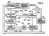
- the transceiver 150 produces the RF excitation field B 1 through power amplifier 151 at a coil 152A and receives the resulting signal induced in a coil 152B.
- the coils 152A and B may be separate as shown in FIG. 2, or they may be a single wholebody coil as shown in FIG. 1.
- the base, or carrier, frequency of the RF excitation field is produced under control of a frequency synthesizer 200 which receives a set of digital signals from the CPU module 119 and pulse generator module 121. These digital signals indicate the frequency and phase of the RF carrier signal produced at an output 201.
- the commanded RF carrier is applied to a modulator and up converter 202 where its amplitude is modulated in response to a signal R(t) also received from the pulse generator module 121.
- the signal R(t) defines the envelope of the RF excitation pulse to be produced and is produced in the module 121 by sequentially reading out a series of stored digital values. These stored digital values may, in turn, be changed from the operator console 100 to enable any desired RF pulse envelope to be produced.
- the MR signal produced by the subject is picked up by the receiver coil 152B and applied through the preamplifier 153 to the input of a receiver attenuator 207.
- the receiver attenuator 207 further amplifies the signal by an amount determined by a digital attenuation signal received from the backplane 118.
- the received signal is at or around the Larmor frequency, and this high frequency signal is down converted in a two step process by a down converter 208 which first mixes the MR signal with the carrier signal on line 201 and then mixes the resulting difference signal with the 2.5 MHz reference signal on line 204.
- the down converted MR signal is applied to the input of an analog-to-digital (A/D) converter 209 which samples and digitizes the analog signal and applies it to a digital detector and signal processor 210 which produces 16 bit in-phase (I) values and 16-bit quadrature (Q) values corresponding to the received signal.
- A/D analog-to-digital
- the resulting stream of digitized I and Q values of the received signal are output through backplane 118 to the memory module 160 where they are normalized in accordance with the present invention and then employed to reconstruct an image.
- Vibrating magnetic field b(t), irrespective of its vibrational modes, must satisfy the Laplace equation ⁇ 2 b(t) 0.
- b o (t) is a spatially invariant magnetic field;
- g x (t), g y (t), and g z (t) are spatially linear gradient magnetic fields in the x, y, and z directions, respectively; and the omitted terms are spatially higher order magnetic fields.
- Equation (1) depend on a time variable t.
- b o (t) is also referred to as a main magnetic field perturbation
- g x (t) as a frequency-encoding or readout gradient perturbation
- g y (t) as a phase-encoding gradient perturbation
- g z (t) as a slice-selection gradient perturbation.
- Equation (1) may include multiple vibrational components, each component being defined by four parameters - an amplitude, a frequency, a phase, and a damping time constant.
- b o (t) can be expressed as: where M o is the total number of vibrational modes, a m is an amplitude, f m is a frequency, ⁇ m is a phase, ⁇ m is a damping time constant, and m is an index of the vibrational mode.
- Equation (1) the three linear gradient terms (g x (t), g y (t), and g z (t)) in Equation (1) can be expressed as: where M x, M y, and M z are the total number of vibrational modes; g x,m , g y,m , and g z,m are the amplitudes; f x,m , f y,m , and f z,m are the frequencies; ⁇ x,m , ⁇ y,m, and ⁇ z,m are the phases; and ⁇ x,m , ⁇ y,m , and ⁇ z,m are the damping time constants for g x (t), g y (t), and g z (t), respectively.
- Equations (2a) - (2d) i.e., with non-negligible damping effect, instead of Equations (3a) - (3d).
- one or more pulse sequences i.e., RF pulses and gradient pulses
- the pulse sequence causes one or more MR signals to be emitted from the excited object of interest and acquires the MR signal.
- Each MR signal provides one row of k y -space data having p data points. In this manner, sampling a total of q MR signals will result in acquiring the p x q array of raw k-space data points, sufficient to perform image reconstruction of the object of interest.
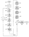
- the scheme includes a start loop step 600, a prepare magnetic field b(t) step 602, a calculate vibration component of b o,n (t) step 604, a calculate vibration component of g x,n (t) step 606, a calculate vibration component of g y,n (t) step 608, a calculate vibration component of g z (t) step 610, an initiate image data acquisition step 612, a compensate error induced by g z (t) vibration component step 614, a compensate error induced by b o,n (t) vibration component step 616, a compensate error induced by g x,n (t) vibration component step 618, a compensate error induced by g y,n (t) vibration component step 620, an image reconstruction step 622, a decision step 624, an end loop step 626, and an incrementor step 628.
- n 1, 2, ..., q times such that all vibration error components corresponding to the vibrating magnetic field b(t) for each MR echo signal, or in another words, each row of k-space data, can be identified, quantified, and utilized to perform the error compensation on the corresponding k-space data.
- the vibration error components calculated in steps 604-610 are utilized by the system control 122 and/or the computer system 107 to perform the compensate steps 614-620.
- an operator initiates the MR imaging system, i.e., start loop step 600, to acquire the MR image of the object of interest using the SE pulse sequence.
- the operator may directly specify the SE pulse sequence from among a list of pulse sequences; the system may be preset to the SE pulse sequence; or based on scan time, image resolution, type of tissue to be imaged, and other requirements, the system may select the SE pulse sequence.
- this pulse sequence will be configured including carrying out the prepare vibrating magnetic field b(t) step 602.
- Prepare step 602 includes configuring the frequencies, amplitudes, and initial phases of b o (t), g x (t), g y (t), and g z (t) comprising b(t).
- the SE pulse sequence includes a 90° RF pulse 300, a 180° RF pulse 302, and a data acquisition window 304 (during which the readout gradient is on).
- the time from the 90° RF pulse 300 to the 180° RF pulse 302 is referred to as a half echo time ⁇ .
- the data acquisition window 304 is turned on after the 180° RF pulse 302, from t 1 ⁇ t ⁇ t 1 +T, where time t 1 ⁇ 2 ⁇ and T is a duration of the data acquisition window.
- the data acquisition window 304 is also referred to as an analog-to-digital converter (ADC) window.
- ADC analog-to-digital converter
- the scheme is applicable for the SE pulse sequence including a fractional echo acquisition or a full echo acquisition.
- steps 604-610 will be carried out.
- steps 604-610 for the n th echo or TR are completed before the corresponding pulse sequence for the n th echo or TR is applied to the object of interest to acquire the n th row of k-space data.
- steps 604 - 610 are shown in successive order, steps 604 - 610 may be performed in any order or even simultaneously as long as steps 604 - 610 are completed prior to the initiation of the n th pulse sequence. In this manner, the vibration error components can be compensated for before, during, or after the data acquisition.
- the vibration error component for b o,n (t) step 604 produces a phase error ⁇ o (t).
- the phase error ⁇ o (t) can be expressed by three terms: (1) the first term covering the time period from the 90° RF pulse 300 to the 180° RF pulse 302 (0 ⁇ t ⁇ ⁇ ); (2) the second term covering the time period from the 180° RF pulse 302 to the beginning of the data acquisition window 306 ( ⁇ ⁇ t ⁇ t 1 ); and (3) the third term covering the time period during the data acquisition window 306 (t 1 ⁇ t' ⁇ t) (see FIG. 4).
- the phase error ⁇ o (t) represents the total phase error (or vibration error component) from the vibrating b o (t) that will occur for the first TR period during the data acquisition.
- Equation (5) can be generalized to calculate a phase error ⁇ o,n (t) of b o,n (t) for any n th TR period within a given MR image acquisition:
- step 604 the phase error ⁇ o,n (t) of b o,n (t) for the n th row of k-space data to be acquired is calculated using Equations (7a) and (7b).
- ⁇ o,n (t) for the n th echo or TR can be solved either numerically or analytically.
- the vibration error component of g x (t) produces a k x -space displacement error ⁇ k x (t).
- the k x -space displacement error ⁇ k x (t) results in k-space data distortion in the k x direction.
- step 606 the k x -space displacement error ⁇ k x,n (t) of g x,n (t) for the n th row of k-space data to be acquired is calculated using Equations (8a) and (8b).
- Equations (8a) and (8b) Depending on the form of g x,n (t), ⁇ k x,n (t) can be solved either numerically or analytically.
- the vibration error component of g y (t) produces a k y -space displacement error ⁇ k y (t).
- the k y -space displacement error causes k-space data points to be distorted in the k y direction.
- the k y -space displacement error ⁇ k y,n (t) of g y,n (t) for the n th row of k-space data to be acquired is calculated using Equations (9a) and (9b).
- the k y -space displacement error ⁇ k y,n (t) may be mathematically solved by numerical or analytical methods.
- the vibration error component of g z (t) produces a slice-selection gradient error ⁇ k z .
- ⁇ k z can be approximated with a time-independent function, ⁇ k z,n , which is evaluated using a time interval from the n th 90° RF pulse to the center of the n th echo.
- step 612 the SE pulse sequence configured to acquire the n th row of k-space data is applied to the object of interest.
- the compensate step 614 occurs prior to the image data acquisition of the n th row of k-space data.
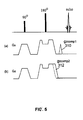
- the slice-selection gradient G z (t) for the n th TR is modified by including a correction pulse or waveform configured from the calculated ⁇ k z,n for the n th TR.
- the correction pulse or waveform can be (a) a blip gradient pulse 310 g zcomp1 (see FIG. 5(a)) having an area under the pulse of - ⁇ k z,n /2 ⁇ , or (b) an additional crusher or slice refocusing gradient pulse 312 g zcomp2 (see FIG. 5(b)) also having an area under the pulse of - ⁇ k z,n /2 ⁇ .
- the correction pulse or waveform functions to "cancel" the ⁇ k z,n error induced by the original vibrating g z (t) for the n th TR.
- the blip gradient pulse 310 is shown in FIG. 5(a) as occurring after the n th 180° RF pulse, it can alternatively perform the compensation from any time after the n th 90° RF pulse to before the start of the n th echo.
- the shape of the blip gradient pulse 310 is flexible, and not limited to the triangular shape shown. However, if a positive pulse is used in the time period between the 180° RF pulse and the start of the echo, then a negative pulse would have to be implemented when used in the time period between the 90° and 180° RF pulses (to offset the phase reversal effect of the 180° RF pulse).
- the additional gradient pulse 312 can also occur at any time after the 90° RF pulse to before the start of the echo, be any pulse shape, and would have to flip the polarity when between the 90° and 180° RF pulses.
- steps 614 - 620 are shown in consecutive order, steps 614 - 620 do not necessarily follow this order and may be performed simultaneously.
- the phase error ⁇ o,n (t) induced by b o,n (t) can be compensated for in the n th row of k-space data after the data acquisition but before image reconstruction.
- the compensation or correction comprises using the phase error ⁇ o,n (t) for the n th TR (calculated using Equation (7b)) to perform a phase subtraction with each k-space data point in the n th row.
- compensate step 616 may comprise performing the correction of ⁇ o,n (t) for the n th TR while the n th row data acquisition is in progress.
- the phase error ⁇ o,n (t) for the n th TR can be compensated for by dynamically adjusting the phase of the receiver portion of transceiver 150.
- phase error ⁇ o,n (t) for the n th TR may be corrected for by accordingly adjusting the main magnetic field or changing the receiver frequency for the n th TR before the acquisition of the n th k-space data.
- This pre-execution compensation approach is particularly effective when b o,n (t) is a constant value for the entire n th row of k-space.
- the k x -space displacement error ⁇ k x,n (t) induced by g x,n (t) and the k y -space displacement error ⁇ k y,n (t) induced by g y,n (t), respectively, will be compensated for in the n th row of acquired k-space data before image reconstruction.
- the displacement errors ⁇ k x,n (t) and ⁇ k y,n (t) for the n th TR (calculated using Equations (8b) and (9b)) are used to restore the distorted k-space to a rectilinear grid using one of known regridding algorithms.
- the gradient errors caused by the magnet vibration, g x,n (t) and g y,n (t), for the n th TR can be compensated through pulse sequence modification.
- each of the two error terms of g x,n (t) and g y,n (t), respectively, is further divided into a pre-acquisition error and an acquisition error.
- the pre-acquisition errors can be compensated using a readout and a phase-encoding gradient pulse whose area equals to - ⁇ k x,n,pre /(2 ⁇ ) and- ⁇ k y,n,pre /(2 ⁇ ), respectively.
- the compensatory gradient pulses may be independent pulses or may be combined with the existing gradient pulses, such as the dephasing readout gradient pulse and the nominal phase-encoding gradient pulses.
- the readout gradient error g x,n,acq (t) can be compensated by changing the nominal readout gradient from G x (t) to G x (t) ⁇ g x,n,acq (t).
- the phase-encoding gradient error g y,n,acq (t) can be compensated by adding a cancellation gradient equal to ⁇ g y,n,acq (t) to the phase-encoding gradient axis concurrent with the readout gradient.
- the compensation approach based on pulse sequence modification produces k-space data free from the vibration effects. Therefore, the acquired k-space data can be directly used for image reconstruction.
- Image reconstruction is possible using any one of well-known reconstruction techniques such as a Fourier transform with Fermi filters or a Homodyne reconstruction algorithm for fractional echo or fractional number of excitations (NEX) data sets.
- the reconstructed image data set which should now include minimal or no image artifacts caused by magnet vibration, is suitable for image display, storage, transmission to a remote site, film or print record, or other utilization and manipulations, for use in, for example, medical diagnosis or further processing.
- the magnetic field vibration quantification and compensation scheme is applied to an MR image acquired using the FGRE pulse sequence.
- Much of the above description of the scheme with respect to the SE pulse sequence is also applicable with respect to the FGRE pulse sequence. Equations, time intervals of interest, and/or other parameters unique to the implementation of the FGRE pulse sequence will be discussed below.
- the start loop step 600 is entered to initiate the quantification and compensation scheme.
- the prepare b(t) step 602 is carried out as part of the configuration of the FGRE pulse sequence.
- Prepare step 602 includes configuring or specifying the frequencies, amplitudes, and initial phases of b o (t), g x (t), g y (t), and g z (t) comprising b(t).
- the FGRE pulse sequence includes an ⁇ ° RF pulse 400 and a data acquisition window 402 (during which the readout gradient G x (t) is active).
- the ⁇ ° RF pulse 400 is an RF pulse with ⁇ typically ranging from 5 to 90 degrees, and preferably between 30 to 60 degrees.
- the data acquisition window 402, also referred to as an analog-to-digital converter (ADC) window, is turned on at time t t 1 after the ⁇ ° RF pulse 400 and remains on for a T time period.
- ADC analog-to-digital converter
- the FGRE pulse sequence is intended to cover both a fractional echo acquisition case and a full echo acquisition case.
- the timing relationships provided in Equations (4a) - (4c) are applicable for the FGRE pulse sequence shown in FIG. 6.
- phase error ⁇ o,n (t) for the n th TR is calculated by two terms: (1) the first term covering the time period from the n th ⁇ ° RF pulse to the beginning of the n th data acquisition window (0 ⁇ t ⁇ t 1 ), and (2) the second term covering the time period during the n th row data acquisition (t 1 ⁇ t' ⁇ t) (see FIG. 6).
- phase error ⁇ o,n (t) for the n th TR using the FGRE pulse sequence is given by modifying Equation (7b) to: where ⁇ is the gyromagnetic constant and b o,n (t) is given in Equation (7a). Notice there is no need to take into account the phase reversal effect because no refocusing RF pulses are used in the FGRE pulse sequence.
- Equation (12) k x -space displacement error ⁇ k x,n (t) for the n th TR using the FGRE pulse sequence is calculated using Equation (12) except substituting b o,n (t) with g x,n (t) in Equation (8a) to:
- Equation (12) k y -space displacement error ⁇ k y,n (t) for the n th TR using the FGRE pulse sequence is calculated using Equation (12) except substituting b o,n (t) with g y,n (t) in Equation (9a) to:
- slice-selection gradient error ⁇ k z,n for the n th TR using the FGRE pulse sequence is given by modifying Equation (10) to cover the time interval from the n th ⁇ ° RF pulse to the center of the n th MR echo signal:
- Equation (15) may also be expressed as: where g z,n (t) is given by Equation (10b).
- the appropriate compensate steps 614-620 can be carried out to correct the n th row of k-space data as discussed above.
- the correction pulse or waveform would have an area under the pulse of - ⁇ k z,n /2 ⁇ .
- the correction pulse or waveform may be the blip gradient pulse or the additional crusher or slice refocusing gradient pulse as shown in FIG. 5(a)-5(b), respectively.
- the correction pulse could be added anywhere from after the n th ⁇ ° RF pulse to before the start of the n th echo. But since no refocusing RF pulses are utilized, there is no need to negate the polarity of the correction pulse to offset the phase reversal effect.
- the magnetic field vibration quantification and compensation scheme is shown applied to an MR image acquired using the FSE pulse sequence.
- SE pulse sequence the earlier description provided with respect to the SE pulse sequence is applicable to this pulse sequence, with variations in equations and other parameters discussed below.
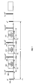
- the FSE pulse sequence includes a 90° RF pulse 500, a first 180° RF pulse 502, a first data acquisition window 504, a second 180° RF pulse 506, a second data acquisition window 508, a third 180° RF pulse 510, and a third data acquisition window 512.
- the first 180° RF pulse 502 follows the 90° RF pulse 500 after a time interval ⁇ .
- the second 180° RF pulse 506 is executed.
- Each of the windows 504, 508, 512 is turned on for a time period T.
- FSE pulse sequences are more complicated than SE or FGRE pulse sequences, its vibration error components are also more complex.
- the multiple phase reversal effects caused by the 180° RF pulses (i.e., refocusing pulse trains) and stimulated echoes caused by non-ideal refocusing pulse trains need to be taken into account.
- stimulated echo pathways can be dephased using non-constant crusher gradient waveforms, as shown in "High-field MR Microscopy Using Fast Spin Echoes," by X. Zhou et al., Magnetic Resonance in Medicine, 30:60-67 (1993), and are therefore negligible.
- stimulated echo pathways are not as easily ignored in FSE pulse sequences; however, such assumptions permit reasonable approximations when the primary echoes dominate the signals. Under this condition, image artifacts can at least be reduced if not eliminated.
- Each vibration error ⁇ c,a (t) will be associated with its corresponding n th k-space row according to the FSE view ordering tables.
- the FSE view ordering table relates each echo to a n th k-space row such that the plurality of echoes emitted in all the shots can be properly identified and indexed.
- k x -space displacement error ⁇ k x,c,a (t) of g x,a (t) for the cth echo in the ath shot (in other words the n th row of k-space data) using the FSE pulse sequence is calculated using an equation similar to Equation (18) but substituting b 0,a (t) with g x,a (t).
- k y -space displacement error ⁇ k y,c,a (t) of g y,a (t) for the c th echo in the a th shot is calculated using an equation similar to Equation (18) but substituting b 0,a (t) with g y,a (t).
- slice-selection gradient error ⁇ k z,c,a of g z (t) for the c th echo in the ath shot (the n th row of k-space data) is calculated from the ath 90° RF pulse to the center of the c th echo.
- Slice-selection gradient error ⁇ k z,c,a can be calculated using Equation (19): where
- the correction pulse which is added to or combined with the slice-selection gradient, can be (a) a blip gradient pulse g zcomp,c,a having an area under the pulse of - ⁇ k z,c,a /(2 ⁇ ), or (b) an additional crusher or slice refocusing gradient pulse g' zcomp,c,a also having an area under the pulse of - ⁇ k z,c,a /(2 ⁇ ).
- j blip gradient pulses such as blip gradient pulses 710,712,714, etc.
- the blip gradient pulses can be positive or negative pulses.
- the j compensation gradient pulses can be combined with the existing crusher or slice refocusing gradient pulses 716,718,720, etc. having additional areas of - ⁇ k z,1,a /(2 ⁇ ), - ⁇ k z,2,a /(2 ⁇ ), - ⁇ k z,3,a /(2 ⁇ ), etc., respectively (see FIG. 8(b)).
- Each additional gradient is applied such that it occurs after its corresponding refocusing RF pulse.
- Compensation for the other errors, ⁇ c,a (t), ⁇ k x,c,a (t), and ⁇ k y,c,a (t) can be carried out by receiver phase adjustment and k-space regridding as discussed for the SE pulse sequence.
- image reconstruction step 222 occurs using well-known reconstruction techniques. In this manner, image artifacts caused by undesirable magnet or magnetic field vibrations can be eliminated or reduced in the MR image acquired using the FSE pulse sequence.
Landscapes
- Health & Medical Sciences (AREA)
- Physics & Mathematics (AREA)
- Life Sciences & Earth Sciences (AREA)
- Nuclear Medicine, Radiotherapy & Molecular Imaging (AREA)
- General Health & Medical Sciences (AREA)
- Radiology & Medical Imaging (AREA)
- Engineering & Computer Science (AREA)
- High Energy & Nuclear Physics (AREA)
- Signal Processing (AREA)
- Medical Informatics (AREA)
- Condensed Matter Physics & Semiconductors (AREA)
- Biophysics (AREA)
- Pathology (AREA)
- Biomedical Technology (AREA)
- Heart & Thoracic Surgery (AREA)
- General Physics & Mathematics (AREA)
- Molecular Biology (AREA)
- Surgery (AREA)
- Animal Behavior & Ethology (AREA)
- Public Health (AREA)
- Veterinary Medicine (AREA)
- Magnetic Resonance Imaging Apparatus (AREA)
Applications Claiming Priority (6)
| Application Number | Priority Date | Filing Date | Title |
|---|---|---|---|
| US16552399P | 1999-11-15 | 1999-11-15 | |
| US165523P | 1999-11-15 | ||
| US468960 | 1999-12-22 | ||
| US09/468,960 US6329821B1 (en) | 1999-11-15 | 1999-12-22 | Method and apparatus to compensate for image artifacts caused by magnet vibration in an MR imaging system |
| US09/469,864 US6380738B1 (en) | 1999-11-15 | 1999-12-22 | Method and apparatus for reducing image artifacts caused by magnet vibration in an MR imaging system |
| US469864 | 1999-12-22 |
Publications (3)
| Publication Number | Publication Date |
|---|---|
| EP1102081A2 true EP1102081A2 (de) | 2001-05-23 |
| EP1102081A3 EP1102081A3 (de) | 2003-05-28 |
| EP1102081B1 EP1102081B1 (de) | 2007-08-01 |
Family
ID=27389161
Family Applications (1)
| Application Number | Title | Priority Date | Filing Date |
|---|---|---|---|
| EP00310012A Expired - Lifetime EP1102081B1 (de) | 1999-11-15 | 2000-11-10 | Verfahren und Gerät zur Kompensation von Bildartefakten, die durch Vibration des Magneten in einem System der bildgebenden magnetischen Resonanz verursacht werden |
Country Status (4)
| Country | Link |
|---|---|
| EP (1) | EP1102081B1 (de) |
| JP (1) | JP2001187041A (de) |
| KR (1) | KR100758084B1 (de) |
| DE (1) | DE60035758T2 (de) |
Cited By (2)
| Publication number | Priority date | Publication date | Assignee | Title |
|---|---|---|---|---|
| EP1102082B1 (de) * | 1999-11-15 | 2008-03-26 | General Electric Company | Verfahren und Gerät zur Verringerung von Bildartefakten, die durch Vibration des Magneten in einem System der bildgebenden magnetischen Resonanz verursacht sind |
| CN111103558A (zh) * | 2019-12-25 | 2020-05-05 | 上海联影医疗科技有限公司 | 信号获取方法、装置、计算机设备和存储介质 |
Families Citing this family (2)
| Publication number | Priority date | Publication date | Assignee | Title |
|---|---|---|---|---|
| JP3844646B2 (ja) * | 2000-09-29 | 2006-11-15 | ジーイー・メディカル・システムズ・グローバル・テクノロジー・カンパニー・エルエルシー | 磁気共鳴信号獲得装置、記録媒体および磁気共鳴撮影装置 |
| JP2002143115A (ja) * | 2000-10-30 | 2002-05-21 | Ge Medical Systems Global Technology Co Llc | Mrイメージング方法、位相エラー測定方法およびmri装置 |
Family Cites Families (3)
| Publication number | Priority date | Publication date | Assignee | Title |
|---|---|---|---|---|
| JPH01141656A (ja) * | 1987-11-30 | 1989-06-02 | Yokogawa Medical Syst Ltd | Nmrイメージング装置の磁場ドリフト補正方法 |
| US4885542A (en) * | 1988-04-14 | 1989-12-05 | The Regents Of The University Of California | MRI compensated for spurious NMR frequency/phase shifts caused by spurious changes in magnetic fields during NMR data measurement processes |
| DE69326202T2 (de) * | 1992-06-29 | 2000-04-13 | Koninklijke Philips Electronics N.V., Eindhoven | Verfahren und Gerät zur Kernresonanzabbildung |
-
2000
- 2000-11-10 EP EP00310012A patent/EP1102081B1/de not_active Expired - Lifetime
- 2000-11-10 DE DE60035758T patent/DE60035758T2/de not_active Expired - Fee Related
- 2000-11-14 KR KR1020000067447A patent/KR100758084B1/ko not_active Expired - Fee Related
- 2000-11-14 JP JP2000346015A patent/JP2001187041A/ja not_active Withdrawn
Cited By (3)
| Publication number | Priority date | Publication date | Assignee | Title |
|---|---|---|---|---|
| EP1102082B1 (de) * | 1999-11-15 | 2008-03-26 | General Electric Company | Verfahren und Gerät zur Verringerung von Bildartefakten, die durch Vibration des Magneten in einem System der bildgebenden magnetischen Resonanz verursacht sind |
| CN111103558A (zh) * | 2019-12-25 | 2020-05-05 | 上海联影医疗科技有限公司 | 信号获取方法、装置、计算机设备和存储介质 |
| CN111103558B (zh) * | 2019-12-25 | 2022-03-25 | 上海联影医疗科技股份有限公司 | 信号获取方法、装置、计算机设备和存储介质 |
Also Published As
| Publication number | Publication date |
|---|---|
| JP2001187041A (ja) | 2001-07-10 |
| EP1102081A3 (de) | 2003-05-28 |
| DE60035758D1 (de) | 2007-09-13 |
| KR20010060324A (ko) | 2001-07-06 |
| DE60035758T2 (de) | 2008-04-30 |
| KR100758084B1 (ko) | 2007-09-11 |
| EP1102081B1 (de) | 2007-08-01 |
Similar Documents
| Publication | Publication Date | Title |
|---|---|---|
| JP4229487B2 (ja) | マクスウェル項誤差を補正する方法 | |
| JP4114989B2 (ja) | 磁気共鳴システムの磁場を補償する方法 | |
| US6078176A (en) | Fast spin echo pulse sequence for diffusion weighted imaging | |
| US5151656A (en) | Correction of nmr data acquired by an echo-planar technique | |
| EP0634664B1 (de) | Vorabtastung mit einer schnellen Spinecho-Sequenz für ein Abbildgerät mit magnetischer Resonanz | |
| JP2529529B2 (ja) | Nmrシステム及び別々に収集された1組のnmr信号から像を発生する方法 | |
| JP4427152B2 (ja) | Mriシステムによる画像形成方法及びmriシステム | |
| US6472872B1 (en) | Real-time shimming of polarizing field in magnetic resonance system | |
| US6242916B1 (en) | Partial fourier acquistion of MR data over a limited field of view and image reconstruction | |
| US6380738B1 (en) | Method and apparatus for reducing image artifacts caused by magnet vibration in an MR imaging system | |
| US7148685B2 (en) | Magnetic resonance imaging with fat suppression | |
| US6329821B1 (en) | Method and apparatus to compensate for image artifacts caused by magnet vibration in an MR imaging system | |
| US4968935A (en) | Selective rephasing of NMR signals to suppress motion artifacts | |
| US7054675B2 (en) | Customized spatial saturation pulse sequence for suppression of artifacts in MR images | |
| US5917323A (en) | Correction of axial image signal fall off caused by Maxwell terms | |
| JPH0616757B2 (ja) | 非対称なnmrエコー取得とともに短いパルスシーケンスを使用する高分解能イメージング装置 | |
| JP7761046B2 (ja) | スパイラル取得を用いたスピンエコーmr画像 | |
| US5541513A (en) | MRI center point artifact elimination using realtime receiver phase control | |
| US5233302A (en) | Masking motion ghost artifacts in NMR images | |
| EP1102081B1 (de) | Verfahren und Gerät zur Kompensation von Bildartefakten, die durch Vibration des Magneten in einem System der bildgebenden magnetischen Resonanz verursacht werden | |
| JP7559763B2 (ja) | ウェーブ符号化を用いたパラレルmrイメージング | |
| CN116635733A (zh) | Dixon型水/脂肪分离MR成像 | |
| US20060132132A1 (en) | Method and system for MR scan acceleration using selective excitation and parallel transmission |
Legal Events
| Date | Code | Title | Description |
|---|---|---|---|
| PUAI | Public reference made under article 153(3) epc to a published international application that has entered the european phase |
Free format text: ORIGINAL CODE: 0009012 |
|
| AK | Designated contracting states |
Kind code of ref document: A2 Designated state(s): AT BE CH CY DE DK ES FI FR GB GR IE IT LI LU MC NL PT SE TR |
|
| AX | Request for extension of the european patent |
Free format text: AL;LT;LV;MK;RO;SI |
|
| PUAL | Search report despatched |
Free format text: ORIGINAL CODE: 0009013 |
|
| AK | Designated contracting states |
Designated state(s): AT BE CH CY DE DK ES FI FR GB GR IE IT LI LU MC NL PT SE TR |
|
| AX | Request for extension of the european patent |
Extension state: AL LT LV MK RO SI |
|
| RIC1 | Information provided on ipc code assigned before grant |
Ipc: 7G 01R 33/565 B Ipc: 7G 01R 33/38 A |
|
| 17P | Request for examination filed |
Effective date: 20031128 |
|
| AKX | Designation fees paid |
Designated state(s): DE NL |
|
| 17Q | First examination report despatched |
Effective date: 20050405 |
|
| GRAP | Despatch of communication of intention to grant a patent |
Free format text: ORIGINAL CODE: EPIDOSNIGR1 |
|
| GRAS | Grant fee paid |
Free format text: ORIGINAL CODE: EPIDOSNIGR3 |
|
| GRAA | (expected) grant |
Free format text: ORIGINAL CODE: 0009210 |
|
| AK | Designated contracting states |
Kind code of ref document: B1 Designated state(s): DE NL |
|
| RIN1 | Information on inventor provided before grant (corrected) |
Inventor name: ZHOU, XIAOHONG |
|
| REF | Corresponds to: |
Ref document number: 60035758 Country of ref document: DE Date of ref document: 20070913 Kind code of ref document: P |
|
| PLBE | No opposition filed within time limit |
Free format text: ORIGINAL CODE: 0009261 |
|
| STAA | Information on the status of an ep patent application or granted ep patent |
Free format text: STATUS: NO OPPOSITION FILED WITHIN TIME LIMIT |
|
| 26N | No opposition filed |
Effective date: 20080506 |
|
| PGFP | Annual fee paid to national office [announced via postgrant information from national office to epo] |
Ref country code: NL Payment date: 20081124 Year of fee payment: 9 |
|
| PGFP | Annual fee paid to national office [announced via postgrant information from national office to epo] |
Ref country code: DE Payment date: 20081223 Year of fee payment: 9 |
|
| REG | Reference to a national code |
Ref country code: NL Ref legal event code: V1 Effective date: 20100601 |
|
| PG25 | Lapsed in a contracting state [announced via postgrant information from national office to epo] |
Ref country code: NL Free format text: LAPSE BECAUSE OF NON-PAYMENT OF DUE FEES Effective date: 20100601 |
|
| PG25 | Lapsed in a contracting state [announced via postgrant information from national office to epo] |
Ref country code: DE Free format text: LAPSE BECAUSE OF NON-PAYMENT OF DUE FEES Effective date: 20100601 |