EP1102084A2 - Procédé de détermination de l'orientation de la direction en azimut d'un appareil de navigation - Google Patents
Procédé de détermination de l'orientation de la direction en azimut d'un appareil de navigation Download PDFInfo
- Publication number
- EP1102084A2 EP1102084A2 EP00124592A EP00124592A EP1102084A2 EP 1102084 A2 EP1102084 A2 EP 1102084A2 EP 00124592 A EP00124592 A EP 00124592A EP 00124592 A EP00124592 A EP 00124592A EP 1102084 A2 EP1102084 A2 EP 1102084A2
- Authority
- EP
- European Patent Office
- Prior art keywords
- navigation device
- radiation
- transmitting station
- emitted
- angle
- Prior art date
- Legal status (The legal status is an assumption and is not a legal conclusion. Google has not performed a legal analysis and makes no representation as to the accuracy of the status listed.)
- Granted
Links
Images
Classifications
-
- G—PHYSICS
- G01—MEASURING; TESTING
- G01S—RADIO DIRECTION-FINDING; RADIO NAVIGATION; DETERMINING DISTANCE OR VELOCITY BY USE OF RADIO WAVES; LOCATING OR PRESENCE-DETECTING BY USE OF THE REFLECTION OR RERADIATION OF RADIO WAVES; ANALOGOUS ARRANGEMENTS USING OTHER WAVES
- G01S1/00—Beacons or beacon systems transmitting signals having a characteristic or characteristics capable of being detected by non-directional receivers and defining directions, positions, or position lines fixed relatively to the beacon transmitters; Receivers co-operating therewith
- G01S1/70—Beacons or beacon systems transmitting signals having a characteristic or characteristics capable of being detected by non-directional receivers and defining directions, positions, or position lines fixed relatively to the beacon transmitters; Receivers co-operating therewith using electromagnetic waves other than radio waves
- G01S1/703—Details
- G01S1/7032—Transmitters
-
- G—PHYSICS
- G01—MEASURING; TESTING
- G01C—MEASURING DISTANCES, LEVELS OR BEARINGS; SURVEYING; NAVIGATION; GYROSCOPIC INSTRUMENTS; PHOTOGRAMMETRY OR VIDEOGRAMMETRY
- G01C21/00—Navigation; Navigational instruments not provided for in groups G01C1/00 - G01C19/00
- G01C21/20—Instruments for performing navigational calculations
- G01C21/206—Instruments for performing navigational calculations specially adapted for indoor navigation
-
- G—PHYSICS
- G01—MEASURING; TESTING
- G01C—MEASURING DISTANCES, LEVELS OR BEARINGS; SURVEYING; NAVIGATION; GYROSCOPIC INSTRUMENTS; PHOTOGRAMMETRY OR VIDEOGRAMMETRY
- G01C17/00—Compasses; Devices for ascertaining true or magnetic north for navigation or surveying purposes
-
- G—PHYSICS
- G01—MEASURING; TESTING
- G01S—RADIO DIRECTION-FINDING; RADIO NAVIGATION; DETERMINING DISTANCE OR VELOCITY BY USE OF RADIO WAVES; LOCATING OR PRESENCE-DETECTING BY USE OF THE REFLECTION OR RERADIATION OF RADIO WAVES; ANALOGOUS ARRANGEMENTS USING OTHER WAVES
- G01S1/00—Beacons or beacon systems transmitting signals having a characteristic or characteristics capable of being detected by non-directional receivers and defining directions, positions, or position lines fixed relatively to the beacon transmitters; Receivers co-operating therewith
- G01S1/02—Beacons or beacon systems transmitting signals having a characteristic or characteristics capable of being detected by non-directional receivers and defining directions, positions, or position lines fixed relatively to the beacon transmitters; Receivers co-operating therewith using radio waves
- G01S1/08—Systems for determining direction or position line
- G01S1/44—Rotating or oscillating beam beacons defining directions in the plane of rotation or oscillation
-
- G—PHYSICS
- G01—MEASURING; TESTING
- G01S—RADIO DIRECTION-FINDING; RADIO NAVIGATION; DETERMINING DISTANCE OR VELOCITY BY USE OF RADIO WAVES; LOCATING OR PRESENCE-DETECTING BY USE OF THE REFLECTION OR RERADIATION OF RADIO WAVES; ANALOGOUS ARRANGEMENTS USING OTHER WAVES
- G01S1/00—Beacons or beacon systems transmitting signals having a characteristic or characteristics capable of being detected by non-directional receivers and defining directions, positions, or position lines fixed relatively to the beacon transmitters; Receivers co-operating therewith
- G01S1/02—Beacons or beacon systems transmitting signals having a characteristic or characteristics capable of being detected by non-directional receivers and defining directions, positions, or position lines fixed relatively to the beacon transmitters; Receivers co-operating therewith using radio waves
- G01S1/68—Marker, boundary, call-sign, or like beacons transmitting signals not carrying directional information
-
- G—PHYSICS
- G01—MEASURING; TESTING
- G01S—RADIO DIRECTION-FINDING; RADIO NAVIGATION; DETERMINING DISTANCE OR VELOCITY BY USE OF RADIO WAVES; LOCATING OR PRESENCE-DETECTING BY USE OF THE REFLECTION OR RERADIATION OF RADIO WAVES; ANALOGOUS ARRANGEMENTS USING OTHER WAVES
- G01S1/00—Beacons or beacon systems transmitting signals having a characteristic or characteristics capable of being detected by non-directional receivers and defining directions, positions, or position lines fixed relatively to the beacon transmitters; Receivers co-operating therewith
- G01S1/72—Beacons or beacon systems transmitting signals having a characteristic or characteristics capable of being detected by non-directional receivers and defining directions, positions, or position lines fixed relatively to the beacon transmitters; Receivers co-operating therewith using ultrasonic, sonic or infrasonic waves
- G01S1/725—Marker, boundary, call-sign or like beacons transmitting signals not carrying directional information
-
- G—PHYSICS
- G01—MEASURING; TESTING
- G01S—RADIO DIRECTION-FINDING; RADIO NAVIGATION; DETERMINING DISTANCE OR VELOCITY BY USE OF RADIO WAVES; LOCATING OR PRESENCE-DETECTING BY USE OF THE REFLECTION OR RERADIATION OF RADIO WAVES; ANALOGOUS ARRANGEMENTS USING OTHER WAVES
- G01S1/00—Beacons or beacon systems transmitting signals having a characteristic or characteristics capable of being detected by non-directional receivers and defining directions, positions, or position lines fixed relatively to the beacon transmitters; Receivers co-operating therewith
- G01S1/72—Beacons or beacon systems transmitting signals having a characteristic or characteristics capable of being detected by non-directional receivers and defining directions, positions, or position lines fixed relatively to the beacon transmitters; Receivers co-operating therewith using ultrasonic, sonic or infrasonic waves
- G01S1/76—Systems for determining direction or position line
- G01S1/82—Rotating or oscillating beam beacons defining directions in the plane of rotation or oscillation
-
- G—PHYSICS
- G01—MEASURING; TESTING
- G01S—RADIO DIRECTION-FINDING; RADIO NAVIGATION; DETERMINING DISTANCE OR VELOCITY BY USE OF RADIO WAVES; LOCATING OR PRESENCE-DETECTING BY USE OF THE REFLECTION OR RERADIATION OF RADIO WAVES; ANALOGOUS ARRANGEMENTS USING OTHER WAVES
- G01S5/00—Position-fixing by co-ordinating two or more direction or position line determinations; Position-fixing by co-ordinating two or more distance determinations
- G01S5/02—Position-fixing by co-ordinating two or more direction or position line determinations; Position-fixing by co-ordinating two or more distance determinations using radio waves
- G01S5/08—Position of single direction-finder fixed by determining direction of a plurality of spaced sources of known location
Definitions
- the invention relates to a method for determining the orientation a defined azimuthal main direction of a navigation device located in a closed or open space, the radiation emitted into the room receives electromagnetic waves or ultrasonic waves and evaluates in this regard.
- Radio beacons broadcast a high frequency carrier vibration. This can be unmodulated or an identifier for the beacon include.
- An on-board receiver determines its orientation using a so-called cross antenna. Here, the angle between a defined main axis of the antenna and the incoming beam determined.
- VOR VHF Omnidirectional Radio Range
- Brockhaus “Natural Sciences and Technology”, (Special edition), volume 5, So-Z, 1989, ISBN 3-7653-0455-7, Mannheim, page 220 (keyword: VOR)
- VOR VHF Omnidirectional Radio Range
- a board receiver placed on this system can now Measure the length of time that is emitted from the reception of the omnidirectional Signal until reception of the directional broadcast Signal passes. From this period and the The space sector can be determined in the on-board receiver in which the on-board receiver is currently located.
- the on-board receiver learns nothing about his own orientation in space. The north direction must be determined by himself.
- the VOR method and the ADF method both have the same Disadvantage that it is a method in analog technology aviation. Accordingly, they work poorly under indoor conditions, as reflections of the transmitter radiation on the walls for the necessarily narrow-band signals have bad effects. The use of this known Indoor use is therefore very critical. It is also common to these two methods that they are used for determination the north direction are not suitable. Since they are in the Aviation can be used using a magnetic or gyro compass however, this is not a serious problem. These beacons are called “flyover points" on airways used, so that it is usually sufficient to complete the course at To know radio beacons.
- GPS Global Positioning System
- a recipient determines the location of at least two antennas that are at a fixed distance are mounted to each other. It can therefore face north locate.
- a disadvantage of this is that at least four satellites must be visible. For indoor use is this not possible. Therefore, at least four pseudo radiation sources can be mounted in the room what a considerable effort and considerable associated with it Costs.
- GPS compass receivers are e.g. in EP 0 587 954 A1, US-A-4 384 293 and US-A-4 881 080.
- the object of the invention is a direction detection method to create electromagnetic radiation or ultrasound radiation from a transmitter station in one closed or open space receiving navigation device allows not only the angular position in relation to this broadcasting station, but also on a fixed geographical Direction, preferably the north direction determine. This is particularly intended to ensure that a person carrying the navigation device in one Space within a building through which you get from the broadcasting station communicated local position always reliable Azimuth directional position of the navigation device in space can recognize, the navigation device one in the frame of a travel planning system uses a mobile wireless information device can be.
- the defined geographical direction in which the function of the circulating directional radiation of the transmitter station begins is preferably the north direction.
- the omnidirectional are advantageously from the transmitting station emitted radiation data signals imprinted which for determining the position in the receiving navigation device can be used (so-called beacon function).
- the receiving navigation device can be more convenient Way used in the context of a travel planning system be mobile wireless information device by one person is carried out, the planning and the course of a trip serves and records and processes position data that except for those in the room used for bearing Transmitting stations also from other position determining devices can come from a navigation service available put.
- the mentioned further position determination devices can Be beacons with the computer operating program "Jini®" be operated, and / or beacons housed in lamps are. Such beacons then work when determining the position of the information device as part of a travel planning system with those also used for direction bearing Broadcasting stations in combination.
- Radio waves especially in the frequency range of the centimeter waves, and waves in the infrared range.
- a first form of implementation of the method according to the invention is that of the transmitting station through the omnidirectional Radiation periodically a CDMA (Code Division Multiple Access; Code multiplex) code word is broadcast.
- CDMA Code Division Multiple Access
- the directional radiation is carried out so that the Always beam to the beginning of the code word in the direction of the specified one geographical direction, i.e. preferably in the north direction, shows and turns around by 360 until the next code word begins Degrees rotates, which makes the current angular position specified function for determining the angle ⁇ is formed becomes.
- the radiation emitted by the directional radiation is advantageous second CDMA code word orthogonal to that by the omnidirectional radiation periodically emitted CDMA code word.
- the receiving navigation device previously already synchronized the carrier of the omnidirectional radiation has despread that contained in the directional radiation CDMA signal by correlation and thus determines the Angle ⁇ , at which the distance between the place the receiving navigation device and the transmitting station in relation to the defined geographical direction, that is preferably the north direction.
- FDMA Frequency Division Multiple Access; Frequency Division Multiplexing
- TDMA Time Division Multiple Access; Time Division Multiplex
- SDMA Space Division Multiple Access
- For determining the position of the receiving navigation device can advantageously a cross bearing with two Broadcast stations are made.
- the angle ⁇ between the main direction of the receiving navigation device and the direction to the transmitting station advantageously by means of a cross antenna or an intelligent antenna.
- Using The directional radiation in the Conveniently using a rotating directional antenna or a so-called smart antenna.
- a second form of implementation of a method according to the invention is designed so that the infrared radiation of the Transmitting station by means of luminescent diodes effective in the infrared range, i.e. so-called LEDs, which is broadcast in radiate different spatial directions.
- luminescent diodes effective in the infrared range, i.e. so-called LEDs, which is broadcast in radiate different spatial directions.
- Those in the infrared range Effective luminescent diodes can be used for simplification the determination of the direction in the individual spatial directions send different CDMA code words.
- the one from the broadcasting station Coming infrared radiation is advantageous via a mounted on the receiving navigation device and receive a dome that is transparent to infrared radiation, which maps the upper hemisphere into a plane, then the direction of incidence of those coming from the transmitting station Infrared radiation using a segmented sensitive Semiconductor field is determined, which is under the permeable dome is located.
- a transmitting station S in a room within of a building radiates omnidirectional periodically CDMA code word from which to perform a beacon function Position determination purposes can also be imprinted with data can.
- the broadcast is advantageously with a high carrier frequency, e.g. at 20 GHz, made so the signals are damped as quickly as possible by air absorption become. Such waves can also hit the walls of a As a rule, do not penetrate the room.
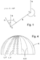
- a receiving navigation device E can measure the angle ⁇ using a Determine cross antenna or an intelligent antenna.
- the Angle ⁇ in the navigation device E is the angle between a defined main direction H of this navigation device E and the direction R of the route to the transmitting station S.
- the receiving navigation device E can be in the frame of a travel planning system uses a mobile wireless information device be carried by a person is used for planning and the process of a trip and for this position data records and processes that other than those im Bearing-transmitting stations can originate from other position determination devices, that provide a navigation service.
- the receiving navigation device E which has already synchronized the omnidirectional carrier, can despread the directed beam by correlation and thus determine in which space segment it is located.
- the navigation device E thus determines the angle ⁇ that exists between the north direction N and the direction R of the route connecting the navigation device E and the transmitting station S.
- a combination of the angles ⁇ and ⁇ can be used in the navigation device E to determine the angle ⁇ at which the main direction H of the navigation device E to the north direction N is held by a person at the moment. In this way, a real compass function is implemented in the navigation device E, apart from the possibility of determining the position.
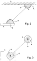
- the one attached to the ceiling D of a room Sending station S here preferably consists of for delivery luminescent diodes L designed by infrared radiation are also a term under the name "LED" s and which in radiate different spatial directions.
- LED LED
- Such an execution in transmission segments A that are under an infrared radiation permeable dome K is special advantageous because such a transmitting station S extremely is inexpensive and easy to implement. They are too Versions possible in which the luminescent diodes in the send different code words in individual spatial directions and thus the direction determination by the infrared radiation Simplify receiving navigation device E.
- dome K permeable for infrared radiation, which maps the upper hemisphere into one plane. Under this There is a dome sensitive to infrared radiation Semiconductors that are all around in receiving segments B with infrared detectors is divided and thus the direction of incidence can determine. Spreading the signal using CDMA code words also makes it usable indoors as well as good suppression of background radiation.
- FIG 4 is a dome transparent to infrared radiation K shown in more detail, either for the transmitting station S can be used and then arranged in transmission segments A.
- Infrared luminescent diode L includes or in the outside same form for the receiving navigation device E can be used and in this case in reception segments B arranged infrared detectors F made of semiconductor material borders.
- the dashed lines correspond Transmitting segments A or receiving segments B.
Landscapes
- Engineering & Computer Science (AREA)
- Radar, Positioning & Navigation (AREA)
- Remote Sensing (AREA)
- Physics & Mathematics (AREA)
- General Physics & Mathematics (AREA)
- Computer Networks & Wireless Communication (AREA)
- Electromagnetism (AREA)
- Automation & Control Theory (AREA)
- Position Fixing By Use Of Radio Waves (AREA)
- Navigation (AREA)
- Mobile Radio Communication Systems (AREA)
Applications Claiming Priority (2)
| Application Number | Priority Date | Filing Date | Title |
|---|---|---|---|
| DE19955044A DE19955044A1 (de) | 1999-11-15 | 1999-11-15 | Verfahren zur Bestimmung der Orientierung einer definierten azimutalen Richtung einer Navigationseinrichtung und Einrichtungen zur Durchführung des Verfahrens |
| DE19955044 | 1999-11-15 |
Publications (3)
| Publication Number | Publication Date |
|---|---|
| EP1102084A2 true EP1102084A2 (fr) | 2001-05-23 |
| EP1102084A3 EP1102084A3 (fr) | 2002-07-31 |
| EP1102084B1 EP1102084B1 (fr) | 2004-04-14 |
Family
ID=7929184
Family Applications (1)
| Application Number | Title | Priority Date | Filing Date |
|---|---|---|---|
| EP00124592A Expired - Lifetime EP1102084B1 (fr) | 1999-11-15 | 2000-11-10 | Procédé de détermination de l'orientation de la direction en azimut d'un appareil de navigation |
Country Status (3)
| Country | Link |
|---|---|
| EP (1) | EP1102084B1 (fr) |
| AT (1) | ATE264511T1 (fr) |
| DE (2) | DE19955044A1 (fr) |
Cited By (6)
| Publication number | Priority date | Publication date | Assignee | Title |
|---|---|---|---|---|
| WO2006116528A3 (fr) * | 2005-04-26 | 2007-03-08 | Rf Code Inc | Systemes d'identification par radiofrequence (rfid) et procedes faisant appel a la localisation infrarouge |
| CN101676746B (zh) * | 2008-09-18 | 2012-06-27 | 财团法人工业技术研究院 | 红外线定位系统及定位方法 |
| EP2498099A1 (fr) * | 2011-03-08 | 2012-09-12 | Höft & Wessell Aktiengesellschaft | Procédé et agencement pour la génération d'un signal modulé dépendant de l'orientation ainsi que procédé et agencement pour la détermination de l'angle d'orientation à partir d'un tel signal modulé dépendant de l'orientation et système d'orientation optique fonctionnant avec celui-ci |
| CN104181498A (zh) * | 2014-09-13 | 2014-12-03 | 邓全龙 | 消防战斗员定位搜救系统及其使用方法 |
| WO2021209166A1 (fr) * | 2020-04-15 | 2021-10-21 | Bundesrepublik Deutschland, Vertreten Durch Das Bundesministerium Für Wirtschaft Und Energie, | Procédé de transmission spatialement concentrée de données entre une station de base et une station mobile, et système de transmission de données |
| CN114018245A (zh) * | 2021-11-08 | 2022-02-08 | 浙江经贸职业技术学院 | 一种摄影取景点位与旅游攻略的导航设备 |
Families Citing this family (3)
| Publication number | Priority date | Publication date | Assignee | Title |
|---|---|---|---|---|
| ATE357670T1 (de) | 2002-01-10 | 2007-04-15 | Siemens Ag | Verfahren zur positionsbestimmung mit hilfe eines funksignals mit rotierender sendecharakteristik |
| DE10200676B4 (de) * | 2002-01-10 | 2007-02-08 | Siemens Ag | Verfahren zur Positionsbestimmung mit Hilfe eines Funksignals mit rotierender Sendecharakteristik und Teilnehmer-Endgerät |
| DE10237545A1 (de) * | 2002-08-16 | 2003-11-13 | Siemens Ag | Verfahren zum Bestimmen eines Winkels der relativen Ausrichtung eines Antennenfeldes einer Funkstation sowie entsprechendes Funksystem und entsprechende Funkstation |
Family Cites Families (6)
| Publication number | Priority date | Publication date | Assignee | Title |
|---|---|---|---|---|
| US4277170A (en) * | 1979-11-01 | 1981-07-07 | Miles Richard B | Laser beacon and optical detector system for aircraft collision hazard determination |
| CA1185085A (fr) * | 1983-12-30 | 1985-04-09 | Laurent J. Paquet | Systeme coordinateur de visee en azimuth |
| JPS61223679A (ja) * | 1985-03-29 | 1986-10-04 | Toshiba Corp | 方位測定装置 |
| DE3526564A1 (de) * | 1985-07-25 | 1987-02-05 | Krupp Gmbh | Containerumschlaganlage |
| JPH0659725A (ja) * | 1992-08-10 | 1994-03-04 | Sekisui Chem Co Ltd | 移動体の位置及び方位測定装置 |
| EP1042686A2 (fr) * | 1997-12-24 | 2000-10-11 | Television New Zealand Limited | Amelioration concernant les determinations de positions |
-
1999
- 1999-11-15 DE DE19955044A patent/DE19955044A1/de not_active Withdrawn
-
2000
- 2000-11-10 AT AT00124592T patent/ATE264511T1/de not_active IP Right Cessation
- 2000-11-10 EP EP00124592A patent/EP1102084B1/fr not_active Expired - Lifetime
- 2000-11-10 DE DE50006057T patent/DE50006057D1/de not_active Expired - Lifetime
Cited By (9)
| Publication number | Priority date | Publication date | Assignee | Title |
|---|---|---|---|---|
| WO2006116528A3 (fr) * | 2005-04-26 | 2007-03-08 | Rf Code Inc | Systemes d'identification par radiofrequence (rfid) et procedes faisant appel a la localisation infrarouge |
| US7486189B2 (en) | 2005-04-26 | 2009-02-03 | Rf Code, Inc | RFID systems and methods employing infrared localization |
| CN101676746B (zh) * | 2008-09-18 | 2012-06-27 | 财团法人工业技术研究院 | 红外线定位系统及定位方法 |
| EP2498099A1 (fr) * | 2011-03-08 | 2012-09-12 | Höft & Wessell Aktiengesellschaft | Procédé et agencement pour la génération d'un signal modulé dépendant de l'orientation ainsi que procédé et agencement pour la détermination de l'angle d'orientation à partir d'un tel signal modulé dépendant de l'orientation et système d'orientation optique fonctionnant avec celui-ci |
| CN104181498A (zh) * | 2014-09-13 | 2014-12-03 | 邓全龙 | 消防战斗员定位搜救系统及其使用方法 |
| CN104181498B (zh) * | 2014-09-13 | 2017-02-15 | 邓全龙 | 消防战斗员定位搜救系统及其使用方法 |
| WO2021209166A1 (fr) * | 2020-04-15 | 2021-10-21 | Bundesrepublik Deutschland, Vertreten Durch Das Bundesministerium Für Wirtschaft Und Energie, | Procédé de transmission spatialement concentrée de données entre une station de base et une station mobile, et système de transmission de données |
| CN114018245A (zh) * | 2021-11-08 | 2022-02-08 | 浙江经贸职业技术学院 | 一种摄影取景点位与旅游攻略的导航设备 |
| CN114018245B (zh) * | 2021-11-08 | 2023-09-15 | 浙江经贸职业技术学院 | 一种智能瞄准导航设备 |
Also Published As
| Publication number | Publication date |
|---|---|
| EP1102084B1 (fr) | 2004-04-14 |
| DE50006057D1 (de) | 2004-05-19 |
| ATE264511T1 (de) | 2004-04-15 |
| EP1102084A3 (fr) | 2002-07-31 |
| DE19955044A1 (de) | 2001-08-09 |
Similar Documents
| Publication | Publication Date | Title |
|---|---|---|
| DE4002176C2 (de) | GPS-Navigationseinrichtung und Navigationsverfahren für Kraftfahrzeuge | |
| EP1314048B1 (fr) | Systeme pour determiner la position d'un objet | |
| DE69223405T2 (de) | Positionsbestimmungssystem auf Abstand | |
| DE69021900T2 (de) | Mobiles Navigationssystem. | |
| EP0016417B1 (fr) | Dispositif de surveillance d'aéroport fonctionnant selon le procédé d'intérrogation-réponse du radar secondaire | |
| DE60219399T2 (de) | System zur Ortung eines Senders | |
| DE3426851C1 (de) | Satelliten-Navigationssystem | |
| DE60212580T2 (de) | Ortungssystem und Verfahren | |
| DE60316818T2 (de) | System und verfahren zur elektromagnetischen nahfeld-entfernungsmessung | |
| EP3289385B1 (fr) | Dispositif et procédé permettant de produire et de fournir des informations de position | |
| EP0814345A2 (fr) | Système de positionnement d'objet mobile, en particulier pour véhicules | |
| EP2247960A1 (fr) | Dispositif et procédé d'évaluation de direction améliorée et de décodage au moyen de signaux radar secondaires | |
| DE3152340T5 (en) | Satellite-based vehicle position determining system | |
| EP1102084B1 (fr) | Procédé de détermination de l'orientation de la direction en azimut d'un appareil de navigation | |
| DE1286594B (de) | Nachrichtensystem zum UEbermitteln von Nachrichten zwischen Raumflugkoerpern und einer Basisstelle | |
| DE102016225886A1 (de) | Verfahren und Vorrichtung zur Positionsbestimmung | |
| DE19904842A1 (de) | Überwachungssystem für terristrische Navigations- und Flughafenlandesysteme | |
| DE69625274T2 (de) | Überwachungssystem | |
| DE60225394T2 (de) | Verfahren und Sytem zur geographischen Ortung in Kommunikations- Netzwerken und Terminal dafür | |
| DE102009053872A1 (de) | Verfahren zur Lokalisierung eines passiven RFID-Transponders | |
| DE19602053A1 (de) | Einrichtung zur Überwachung des Abstandes zweier Objekte | |
| EP2065722B1 (fr) | Dispositif destiné au positionnement d'objets ou de personnes, notamment pour une recherche de victimes d'une avalanche et procédé de positionnement | |
| DE19907024A1 (de) | Verfahren und Vorrichtung zur Positionsbestimmung | |
| DE102019211812A1 (de) | Verfahren zur Ortung eines Objekts | |
| EP1635185A2 (fr) | Procédé et appareil pour déterminer la position d'une station d'abonné d'un réseau de télécommunication sans fil |
Legal Events
| Date | Code | Title | Description |
|---|---|---|---|
| PUAI | Public reference made under article 153(3) epc to a published international application that has entered the european phase |
Free format text: ORIGINAL CODE: 0009012 |
|
| AK | Designated contracting states |
Kind code of ref document: A2 Designated state(s): AT BE CH CY DE DK ES FI FR GB GR IE IT LI LU MC NL PT SE TR |
|
| AX | Request for extension of the european patent |
Free format text: AL;LT;LV;MK;RO;SI |
|
| PUAL | Search report despatched |
Free format text: ORIGINAL CODE: 0009013 |
|
| AK | Designated contracting states |
Kind code of ref document: A3 Designated state(s): AT BE CH CY DE DK ES FI FR GB GR IE IT LI LU MC NL PT SE TR |
|
| AX | Request for extension of the european patent |
Free format text: AL;LT;LV;MK;RO;SI |
|
| 17P | Request for examination filed |
Effective date: 20021019 |
|
| AKX | Designation fees paid |
Designated state(s): AT BE CH CY DE DK ES FI FR GB GR IE IT LI LU MC NL PT SE TR |
|
| GRAP | Despatch of communication of intention to grant a patent |
Free format text: ORIGINAL CODE: EPIDOSNIGR1 |
|
| GRAS | Grant fee paid |
Free format text: ORIGINAL CODE: EPIDOSNIGR3 |
|
| GRAA | (expected) grant |
Free format text: ORIGINAL CODE: 0009210 |
|
| AK | Designated contracting states |
Kind code of ref document: B1 Designated state(s): AT BE CH CY DE DK ES FI FR GB GR IE IT LI LU MC NL PT SE TR |
|
| PG25 | Lapsed in a contracting state [announced via postgrant information from national office to epo] |
Ref country code: IT Free format text: LAPSE BECAUSE OF FAILURE TO SUBMIT A TRANSLATION OF THE DESCRIPTION OR TO PAY THE FEE WITHIN THE PRESCRIBED TIME-LIMIT;WARNING: LAPSES OF ITALIAN PATENTS WITH EFFECTIVE DATE BEFORE 2007 MAY HAVE OCCURRED AT ANY TIME BEFORE 2007. THE CORRECT EFFECTIVE DATE MAY BE DIFFERENT FROM THE ONE RECORDED. Effective date: 20040414 Ref country code: IE Free format text: LAPSE BECAUSE OF FAILURE TO SUBMIT A TRANSLATION OF THE DESCRIPTION OR TO PAY THE FEE WITHIN THE PRESCRIBED TIME-LIMIT Effective date: 20040414 Ref country code: CY Free format text: LAPSE BECAUSE OF FAILURE TO SUBMIT A TRANSLATION OF THE DESCRIPTION OR TO PAY THE FEE WITHIN THE PRESCRIBED TIME-LIMIT Effective date: 20040414 Ref country code: NL Free format text: LAPSE BECAUSE OF FAILURE TO SUBMIT A TRANSLATION OF THE DESCRIPTION OR TO PAY THE FEE WITHIN THE PRESCRIBED TIME-LIMIT Effective date: 20040414 Ref country code: FI Free format text: LAPSE BECAUSE OF FAILURE TO SUBMIT A TRANSLATION OF THE DESCRIPTION OR TO PAY THE FEE WITHIN THE PRESCRIBED TIME-LIMIT Effective date: 20040414 Ref country code: TR Free format text: LAPSE BECAUSE OF FAILURE TO SUBMIT A TRANSLATION OF THE DESCRIPTION OR TO PAY THE FEE WITHIN THE PRESCRIBED TIME-LIMIT Effective date: 20040414 |
|
| REG | Reference to a national code |
Ref country code: GB Ref legal event code: FG4D Free format text: NOT ENGLISH |
|
| REG | Reference to a national code |
Ref country code: CH Ref legal event code: EP |
|
| REF | Corresponds to: |
Ref document number: 50006057 Country of ref document: DE Date of ref document: 20040519 Kind code of ref document: P |
|
| REG | Reference to a national code |
Ref country code: IE Ref legal event code: FG4D Free format text: GERMAN |
|
| REG | Reference to a national code |
Ref country code: CH Ref legal event code: NV Representative=s name: SERVOPATENT GMBH |
|
| GBT | Gb: translation of ep patent filed (gb section 77(6)(a)/1977) |
Effective date: 20040517 |
|
| PG25 | Lapsed in a contracting state [announced via postgrant information from national office to epo] |
Ref country code: DK Free format text: LAPSE BECAUSE OF FAILURE TO SUBMIT A TRANSLATION OF THE DESCRIPTION OR TO PAY THE FEE WITHIN THE PRESCRIBED TIME-LIMIT Effective date: 20040714 Ref country code: GR Free format text: LAPSE BECAUSE OF FAILURE TO SUBMIT A TRANSLATION OF THE DESCRIPTION OR TO PAY THE FEE WITHIN THE PRESCRIBED TIME-LIMIT Effective date: 20040714 Ref country code: SE Free format text: LAPSE BECAUSE OF FAILURE TO SUBMIT A TRANSLATION OF THE DESCRIPTION OR TO PAY THE FEE WITHIN THE PRESCRIBED TIME-LIMIT Effective date: 20040714 |
|
| PG25 | Lapsed in a contracting state [announced via postgrant information from national office to epo] |
Ref country code: ES Free format text: LAPSE BECAUSE OF FAILURE TO SUBMIT A TRANSLATION OF THE DESCRIPTION OR TO PAY THE FEE WITHIN THE PRESCRIBED TIME-LIMIT Effective date: 20040725 |
|
| NLV1 | Nl: lapsed or annulled due to failure to fulfill the requirements of art. 29p and 29m of the patents act | ||
| PG25 | Lapsed in a contracting state [announced via postgrant information from national office to epo] |
Ref country code: AT Free format text: LAPSE BECAUSE OF NON-PAYMENT OF DUE FEES Effective date: 20041110 Ref country code: LU Free format text: LAPSE BECAUSE OF NON-PAYMENT OF DUE FEES Effective date: 20041110 |
|
| PG25 | Lapsed in a contracting state [announced via postgrant information from national office to epo] |
Ref country code: BE Free format text: LAPSE BECAUSE OF NON-PAYMENT OF DUE FEES Effective date: 20041130 Ref country code: MC Free format text: LAPSE BECAUSE OF NON-PAYMENT OF DUE FEES Effective date: 20041130 |
|
| REG | Reference to a national code |
Ref country code: IE Ref legal event code: FD4D |
|
| ET | Fr: translation filed | ||
| PLBE | No opposition filed within time limit |
Free format text: ORIGINAL CODE: 0009261 |
|
| STAA | Information on the status of an ep patent application or granted ep patent |
Free format text: STATUS: NO OPPOSITION FILED WITHIN TIME LIMIT |
|
| 26N | No opposition filed |
Effective date: 20050117 |
|
| BERE | Be: lapsed |
Owner name: DEUTSCHES *ZENTRUM FUR LUFT- UND RAUMFAHRT E.V. Effective date: 20041130 |
|
| PGFP | Annual fee paid to national office [announced via postgrant information from national office to epo] |
Ref country code: FR Payment date: 20061117 Year of fee payment: 7 |
|
| PGFP | Annual fee paid to national office [announced via postgrant information from national office to epo] |
Ref country code: CH Payment date: 20061123 Year of fee payment: 7 Ref country code: GB Payment date: 20061123 Year of fee payment: 7 |
|
| BERE | Be: lapsed |
Owner name: DEUTSCHES *ZENTRUM FUR LUFT- UND RAUMFAHRT E.V. Effective date: 20041130 |
|
| PG25 | Lapsed in a contracting state [announced via postgrant information from national office to epo] |
Ref country code: PT Free format text: LAPSE BECAUSE OF NON-PAYMENT OF DUE FEES Effective date: 20040914 |
|
| REG | Reference to a national code |
Ref country code: CH Ref legal event code: PFA Owner name: DEUTSCHES ZENTRUM FUER LUFT- UND RAUMFAHRT E.V. Free format text: DEUTSCHES ZENTRUM FUER LUFT- UND RAUMFAHRT E.V.# #53175 BONN (DE) -TRANSFER TO- DEUTSCHES ZENTRUM FUER LUFT- UND RAUMFAHRT E.V.# #53175 BONN (DE) |
|
| GBPC | Gb: european patent ceased through non-payment of renewal fee |
Effective date: 20071110 |
|
| PG25 | Lapsed in a contracting state [announced via postgrant information from national office to epo] |
Ref country code: LI Free format text: LAPSE BECAUSE OF NON-PAYMENT OF DUE FEES Effective date: 20071130 Ref country code: CH Free format text: LAPSE BECAUSE OF NON-PAYMENT OF DUE FEES Effective date: 20071130 |
|
| REG | Reference to a national code |
Ref country code: CH Ref legal event code: PL |
|
| REG | Reference to a national code |
Ref country code: FR Ref legal event code: ST Effective date: 20080930 |
|
| PG25 | Lapsed in a contracting state [announced via postgrant information from national office to epo] |
Ref country code: GB Free format text: LAPSE BECAUSE OF NON-PAYMENT OF DUE FEES Effective date: 20071110 |
|
| PG25 | Lapsed in a contracting state [announced via postgrant information from national office to epo] |
Ref country code: FR Free format text: LAPSE BECAUSE OF NON-PAYMENT OF DUE FEES Effective date: 20071130 |
|
| PGFP | Annual fee paid to national office [announced via postgrant information from national office to epo] |
Ref country code: DE Payment date: 20171130 Year of fee payment: 18 |
|
| REG | Reference to a national code |
Ref country code: DE Ref legal event code: R119 Ref document number: 50006057 Country of ref document: DE |
|
| PG25 | Lapsed in a contracting state [announced via postgrant information from national office to epo] |
Ref country code: DE Free format text: LAPSE BECAUSE OF NON-PAYMENT OF DUE FEES Effective date: 20190601 |