EP1102296A2 - Disjoncteur - Google Patents
Disjoncteur Download PDFInfo
- Publication number
- EP1102296A2 EP1102296A2 EP00123896A EP00123896A EP1102296A2 EP 1102296 A2 EP1102296 A2 EP 1102296A2 EP 00123896 A EP00123896 A EP 00123896A EP 00123896 A EP00123896 A EP 00123896A EP 1102296 A2 EP1102296 A2 EP 1102296A2
- Authority
- EP
- European Patent Office
- Prior art keywords
- movable contact
- stem
- contact
- load switch
- contact stem
- Prior art date
- Legal status (The legal status is an assumption and is not a legal conclusion. Google has not performed a legal analysis and makes no representation as to the accuracy of the status listed.)
- Withdrawn
Links
- 238000000034 method Methods 0.000 claims abstract description 4
- 239000000919 ceramic Substances 0.000 claims abstract description 3
- 238000009413 insulation Methods 0.000 claims description 2
- 230000008719 thickening Effects 0.000 description 2
- 239000004020 conductor Substances 0.000 description 1
- 238000000926 separation method Methods 0.000 description 1
Images
Classifications
-
- H—ELECTRICITY
- H01—ELECTRIC ELEMENTS
- H01H—ELECTRIC SWITCHES; RELAYS; SELECTORS; EMERGENCY PROTECTIVE DEVICES
- H01H33/00—High-tension or heavy-current switches with arc-extinguishing or arc-preventing means
- H01H33/60—Switches wherein the means for extinguishing or preventing the arc do not include separate means for obtaining or increasing flow of arc-extinguishing fluid
- H01H33/66—Vacuum switches
- H01H33/666—Operating arrangements
- H01H33/6661—Combination with other type of switch, e.g. for load break switches
-
- H—ELECTRICITY
- H01—ELECTRIC ELEMENTS
- H01H—ELECTRIC SWITCHES; RELAYS; SELECTORS; EMERGENCY PROTECTIVE DEVICES
- H01H33/00—High-tension or heavy-current switches with arc-extinguishing or arc-preventing means
- H01H33/02—Details
- H01H33/04—Means for extinguishing or preventing arc between current-carrying parts
- H01H33/12—Auxiliary contacts on to which the arc is transferred from the main contacts
- H01H33/121—Load break switches
- H01H33/125—Load break switches comprising a separate circuit breaker
- H01H33/127—Load break switches comprising a separate circuit breaker movable with a sectionalising contact arm and operated by such movement
Definitions
- the invention relates to a load switch according to the preamble of claim 1.
- a switch disconnector of the type mentioned becomes, in which the load switch is housed within a push tube, whereby the thrust tube the distance between two fixed when switched on Contact elements bridged.
- the load switch is inside the Push tube and is held in place by a lock during the switch-off process.
- the object of the invention is to provide another solution for a load switch at the beginning to create the kind mentioned.
- the vacuum chamber is held in that the fixed contact stem has a locking head, the so of a resilient locking device long held until on the one hand the push tube a sufficient distance from has the associated contact element and on the other hand the contact point within the vacuum chamber is separated.
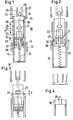
- the load switch 10 according to FIG. 1 has contact elements arranged at a distance from one another 11, 12, which are resiliently pressed in as contact fingers and a thickening 13, 14 at their respective free ends, which have to face each other.
- a push tube 15 made of electrical conductive material which is electrically connected to the thickenings 13 and 14 is and in the switched-on state to bridge the contact element distance serves.
- a vacuum chamber 16 which has a ceramic cylinder, is arranged inside the push tube 15 17, which at both ends by means of a cover 18 and 19 is closed, the cover 19 having an opening, not shown, in its Middle.
- the cover 18 is penetrated by a fixed contact stem 20, the fixed contact stem 20 is connected to the cover 18 in a vacuum-tight manner.
- the inner free end of the fixed contact stem carries a fixed contact piece 21.
- the cover 19 is penetrated by a movable contact stem 22, between a bellows 23 is arranged on the cover 19 and the contact stem 22, by means of which the vacuum chamber is closed in a vacuum-tight manner, with free mobility of the movable contact stem is achieved.
- a movable contact piece 24 On the fixed contact piece 21 facing end of the contact stem 22 is a movable contact piece 24 attached.
- the free end of the fixed contact stem protruding from the cover 18 is provided with a locking head 25 with an enlarged diameter, which is switched on State behind a locking device formed from two locking springs 26 and 27 28 engages; the figure shows two locking arms 26, 27; it can of course also be more.
- a receptacle 29 adjoins the outside of the cover 19, the bottom 30 of the receiving pot 29, see Fig. 2, with the movable contact stem 22 fixed connected is.
- a contact pressure spring 32 Within of the receptacle between the piston 31 and the bottom 30 is a contact pressure spring 32 provided the movable contact stem 22 and thus the movable Contact piece 24 presses against the fixed contact piece 21.
- a return spring 33 is attached at one end to the movable contact stem 22, the other end of which is attached to a bottom 34 of the push tube 15.
- On the push tube 15 is attacked by a switch-off drive, which is indicated by the arrow 35.
- On the movable contact stem 22, a contact pot 36 is also attached, the for an electrically conductive connection between the movable contact stem 22 and the push tube 15 provides.
- the vacuum chamber is opened and the movable contact piece 24 moves away from the fixed contact piece 21 until the distance D is reached which corresponds to the insulation distance of the contact pieces in the vacuum chamber.
- the force of the return spring 33 is greater than that Locking force of the locking device 28 so that the locking head 25 is released and the load switch is moved to its open position.
- the push tube 15 is dimensioned so that the locking head in the off Condition behind the front edge disappears.
- the locking force between the locking head and the locking device is greater than that Maximum force of the return spring and the return spring only reaches about halfway of the entire switching stroke the same spring force as the contact pressure spring.
- the system requires exact coordination between the contact pressure spring the vacuum chamber and the return spring, as well as to the locking device 28
Landscapes
- High-Tension Arc-Extinguishing Switches Without Spraying Means (AREA)
Applications Claiming Priority (2)
| Application Number | Priority Date | Filing Date | Title |
|---|---|---|---|
| DE1999155217 DE19955217A1 (de) | 1999-11-17 | 1999-11-17 | Lastschalter |
| DE19955217 | 1999-11-17 |
Publications (2)
| Publication Number | Publication Date |
|---|---|
| EP1102296A2 true EP1102296A2 (fr) | 2001-05-23 |
| EP1102296A3 EP1102296A3 (fr) | 2003-01-15 |
Family
ID=7929294
Family Applications (1)
| Application Number | Title | Priority Date | Filing Date |
|---|---|---|---|
| EP00123896A Withdrawn EP1102296A3 (fr) | 1999-11-17 | 2000-11-03 | Disjoncteur |
Country Status (2)
| Country | Link |
|---|---|
| EP (1) | EP1102296A3 (fr) |
| DE (1) | DE19955217A1 (fr) |
Cited By (1)
| Publication number | Priority date | Publication date | Assignee | Title |
|---|---|---|---|---|
| WO2013011009A1 (fr) * | 2011-07-21 | 2013-01-24 | Alstom Technology Ltd | Sectionneur pour une installation a isolation gazeuse comportant une ampoule a vide |
Families Citing this family (1)
| Publication number | Priority date | Publication date | Assignee | Title |
|---|---|---|---|---|
| DE102010015043B4 (de) | 2010-04-12 | 2016-01-28 | Schneider Electric Sachsenwerk Gmbh | Elektrischer Leistungsschalter |
Family Cites Families (6)
| Publication number | Priority date | Publication date | Assignee | Title |
|---|---|---|---|---|
| US3399286A (en) * | 1966-03-07 | 1968-08-27 | Powerdyne Inc | High voltage electric swtich |
| JPS5812230A (ja) * | 1981-07-16 | 1983-01-24 | 富士電機株式会社 | 断路器付真空負荷開閉器 |
| DE3407858A1 (de) * | 1984-02-29 | 1984-08-02 | Ernst Prof. Dr.techn.habil. 1000 Berlin Slamecka | Elektrischer vakuumschalter |
| DE4027723A1 (de) * | 1990-08-30 | 1991-01-10 | Slamecka Ernst | Vakuumschaltkammer fuer lasttrennschalter |
| DE4340632A1 (de) * | 1993-11-30 | 1995-06-01 | Abb Patent Gmbh | Elektrische Schalteinrichtung |
| DE19859007A1 (de) * | 1998-12-21 | 2000-06-29 | Abb Patent Gmbh | Lasttrennschalter |
-
1999
- 1999-11-17 DE DE1999155217 patent/DE19955217A1/de not_active Withdrawn
-
2000
- 2000-11-03 EP EP00123896A patent/EP1102296A3/fr not_active Withdrawn
Cited By (2)
| Publication number | Priority date | Publication date | Assignee | Title |
|---|---|---|---|---|
| WO2013011009A1 (fr) * | 2011-07-21 | 2013-01-24 | Alstom Technology Ltd | Sectionneur pour une installation a isolation gazeuse comportant une ampoule a vide |
| FR2978290A1 (fr) * | 2011-07-21 | 2013-01-25 | Alstom Grid Sas | Sectionneur pour une installation a isolation gazeuse comportant une ampoule a vide |
Also Published As
| Publication number | Publication date |
|---|---|
| EP1102296A3 (fr) | 2003-01-15 |
| DE19955217A1 (de) | 2001-05-23 |
Similar Documents
| Publication | Publication Date | Title |
|---|---|---|
| DE69205069T2 (de) | Mittelspannungslastschalter mit reduzierter Steuerenergie. | |
| DE3810453C2 (fr) | ||
| DE69110499T2 (de) | Lastschalter unterstützt durch Varistor. | |
| DE2723552C2 (de) | Elektrischer Druckgasschalter | |
| DE2039240A1 (de) | Druckgasschalter,insbesondere mit Selbstbeblasung | |
| DE4445172C2 (de) | Schaltfeld | |
| DE69109508T2 (de) | Mittelspannungsschalter mit Selbstbeblasung. | |
| DE69109749T2 (de) | Leistungsschalter mit eingebautem Varistor. | |
| EP0157922B1 (fr) | Interrupteur à haute tension | |
| DE69516461T2 (de) | Mittelspannung elektrischer Schalter | |
| DE102013217834B4 (de) | Schaltgerät und Verfahren zum Schalten eines solchen Schaltgerätes | |
| EP0822565B1 (fr) | Disjoncteur électrique à gaz comprimé | |
| WO2006002560A1 (fr) | Ampoule sous vide et ensemble de contacts pour un disjoncteur a vide | |
| DE102010045233A1 (de) | Lasttrennschalter | |
| DE69223292T2 (de) | Mittel- oder Hochspannungslastschalter mit aufeinanderstossenden Lichtbogenkontakten | |
| DE19547098A1 (de) | Leistungsschalter mit einem Einschaltwiderstand | |
| DE2621098A1 (de) | Druckgasschalter | |
| EP0152583B1 (fr) | Interrupteur à haute tension | |
| DE68911962T2 (de) | Hochspannungsschalter mit geringer Antriebsenergie. | |
| DE1261219B (de) | Vakuumschalter | |
| DE102004006476B4 (de) | Lasttrennschalter | |
| DE69604547T2 (de) | Lastschalter mit Einschaltwiderstand und Einfügungsvorrichtung | |
| DE10220110B4 (de) | Vakuumschaltkammer | |
| DE2704389B2 (de) | Trennschalter für metallgekapselte Hochspannungsschaltanlagen | |
| EP1102296A2 (fr) | Disjoncteur |
Legal Events
| Date | Code | Title | Description |
|---|---|---|---|
| PUAI | Public reference made under article 153(3) epc to a published international application that has entered the european phase |
Free format text: ORIGINAL CODE: 0009012 |
|
| AK | Designated contracting states |
Kind code of ref document: A2 Designated state(s): AT BE CH CY DE DK ES FI FR GB GR IE IT LI LU MC NL PT SE TR |
|
| AX | Request for extension of the european patent |
Free format text: AL;LT;LV;MK;RO;SI |
|
| RAP1 | Party data changed (applicant data changed or rights of an application transferred) |
Owner name: ABB PATENT GMBH |
|
| PUAL | Search report despatched |
Free format text: ORIGINAL CODE: 0009013 |
|
| AK | Designated contracting states |
Kind code of ref document: A3 Designated state(s): AT BE CH CY DE DK ES FI FR GB GR IE IT LI LU MC NL PT SE TR |
|
| AX | Request for extension of the european patent |
Free format text: AL;LT;LV;MK;RO;SI |
|
| AKX | Designation fees paid |
Designated state(s): DE FR GB IT NL |
|
| STAA | Information on the status of an ep patent application or granted ep patent |
Free format text: STATUS: THE APPLICATION IS DEEMED TO BE WITHDRAWN |
|
| 18D | Application deemed to be withdrawn |
Effective date: 20030716 |