EP1102363A1 - Connecteur pour appareil électronique et structure de connexion pour connecter avec - Google Patents
Connecteur pour appareil électronique et structure de connexion pour connecter avec Download PDFInfo
- Publication number
- EP1102363A1 EP1102363A1 EP00125035A EP00125035A EP1102363A1 EP 1102363 A1 EP1102363 A1 EP 1102363A1 EP 00125035 A EP00125035 A EP 00125035A EP 00125035 A EP00125035 A EP 00125035A EP 1102363 A1 EP1102363 A1 EP 1102363A1
- Authority
- EP
- European Patent Office
- Prior art keywords
- component
- wire
- electronic devices
- side connector
- connector
- Prior art date
- Legal status (The legal status is an assumption and is not a legal conclusion. Google has not performed a legal analysis and makes no representation as to the accuracy of the status listed.)
- Withdrawn
Links
- 230000008878 coupling Effects 0.000 claims description 24
- 238000010168 coupling process Methods 0.000 claims description 24
- 238000005859 coupling reaction Methods 0.000 claims description 24
- 238000003780 insertion Methods 0.000 claims description 14
- 230000037431 insertion Effects 0.000 claims description 14
- 239000000758 substrate Substances 0.000 description 4
- 230000004075 alteration Effects 0.000 description 1
- 238000001514 detection method Methods 0.000 description 1
- 238000012423 maintenance Methods 0.000 description 1
- 238000004519 manufacturing process Methods 0.000 description 1
- 238000000034 method Methods 0.000 description 1
- 230000004048 modification Effects 0.000 description 1
- 238000012986 modification Methods 0.000 description 1
Images



Classifications
-
- H—ELECTRICITY
- H01—ELECTRIC ELEMENTS
- H01R—ELECTRICALLY-CONDUCTIVE CONNECTIONS; STRUCTURAL ASSOCIATIONS OF A PLURALITY OF MUTUALLY-INSULATED ELECTRICAL CONNECTING ELEMENTS; COUPLING DEVICES; CURRENT COLLECTORS
- H01R13/00—Details of coupling devices of the kinds covered by groups H01R12/70 or H01R24/00 - H01R33/00
- H01R13/46—Bases; Cases
- H01R13/516—Means for holding or embracing insulating body, e.g. casing, hoods
- H01R13/518—Means for holding or embracing insulating body, e.g. casing, hoods for holding or embracing several coupling parts, e.g. frames
-
- H—ELECTRICITY
- H01—ELECTRIC ELEMENTS
- H01R—ELECTRICALLY-CONDUCTIVE CONNECTIONS; STRUCTURAL ASSOCIATIONS OF A PLURALITY OF MUTUALLY-INSULATED ELECTRICAL CONNECTING ELEMENTS; COUPLING DEVICES; CURRENT COLLECTORS
- H01R13/00—Details of coupling devices of the kinds covered by groups H01R12/70 or H01R24/00 - H01R33/00
- H01R13/62—Means for facilitating engagement or disengagement of coupling parts or for holding them in engagement
- H01R13/621—Bolt, set screw or screw clamp
- H01R13/6215—Bolt, set screw or screw clamp using one or more bolts
Definitions
- the present invention relates to a connector for connecting an electric wire component, such as a wire harness, to an electronic device, such as an electronic control unit, and also relates to a connection structure using this connector.
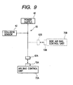
- FIG. 9 shows an example of a wiring arrangement using these connectors.
- FIG. 9 illustrates an example of connection of an air bag control unit 70 A, which is an electronic device, to a power supply 40 and to a collision sensor 42 by using a wire harness 60.
- the wire harness 60 shown in this figure has three terminals at which the power supply 40, the collision sensor 42, and a connector 62A are provided, respectively.
- a connector 72A is provided on the air bag control unit 70A. This connector 72A is coupled to the connector 62A so that the air bag control unit 70A is connected to the power supply 40 and the collision sensor 42 through the wire harness 60.
- a side air bag control unit 70B to the power supply 40 and the collision sensor 42 in such a circuit, in addition to the side air bag control unit 70.
- another wire serving as a branch line is branched from the wire harness 60, as indicated by a dashed line drawn in Fig. 9.
- a connector 62B other than the connector 62A is disposed at an end of the branch line and coupled to a connector 72B mounted on the side air bag control unit 70B.
- an object of the present invention is to eable efficient connection of a common electric wire component to a plurality of electronic devices by using a system of a simple configuration at little expense in time and effort.
- the invention is an electronic device connecting connector for connecting a common electric wire component to a plurality of electronic devices, the electronic device connecting connector comprising a plurality of device-side connectors provided in the electronic devices, respectively and a wire-component-side connector provided at the electric wire component.
- This wire-component-side connector is integrated combination of a plurality of coupling portions able to couple to each of the device-side connectors.
- the invention is a structure for connecting a common electric wire component to each of the electronic devices by using this electronic device connecting connector.
- This structure comprises the device-side connectors, each of which is provided at each of the electronic devices, the wire-component-side connector provided at the electric wire component, and positioning member for fixing a relative position of each of the electronic devices so that a location of each of the coupling portions of this wire-component-side connector coincides with a location of the device-side connectors.
- the coupling portions of the wire-component-side connector can be simultaneously coupled to each of the device-side connectors by adjusting the relative position of each of the electronic devices provided with the device-side connector to a specific relative position (that is, a relative position where the location of each of the coupling portions of the wire-component-side connector coincides with the location of each of the device-side connectors).
- This coupling enables the common connection between the electric wire component provided with the wire-component-side connector and each of the electronic devices.
- the connection between the electric wire component and each of the electronic devices can be established by once performing a connector connecting operation.
- the management of all of such connections can be performed at a place.
- the positioning member for positioning the plurality of electronic devices has, for example, a case for holding the plurality of electronic devices at predetermined positions.
- the case is configured so that during the plurality of electronic devices are held at the predetermined positions in this case, the location of each of the coupling portions of this wire-component-side connector coincides with the location of each of the device-side connectors.
- each of the electronic devices can be stably held at an appropriate position (that is, a position where each of the device-side connectors can be coupled to each of the wire-component-side connector).
- the appropriate placement of the electronic devices is achieved only by setting the electronic devices in the case.
- the positioning member may have positioning portions able to engage with the plurality of electronic devices.
- each of the electronic devices may be fixed at a relative position, at which the location of each of the device-side connectors coincides with the location of the coupling portions of the wire-component-side connector, by engaging the positioning portions with one another.
- a recess portion serving as the positioning portion is provided in one of two electronic devices. Further, a convex portion serving as the positioning portion to be fitted into the recess portion is provided in the other of the two electronic devices. Moreover, a bolt insertion hole is provided in the wire-component-side connector. A screw hole is provided in this bolt insertion hole. The bolt inserted into this bolt insertion hole is screwed into the screw hole to thereby tighten the wire-component-side connector and the device-side connector provided on each of the electronic devices together securely.
- the positioning convex portion is effectively utilized, so that a space, in which the screw hole is provided, can be ensured in the electronic devices. Furthermore, a sufficient fitting force for connecting the device-side connectors to the wire-component-side connector can be ensured by screwing the bolt into this screw hole.
- the structure may be configured so that while the convex portion is fitted into the recess portion, the device-side connectors of both the electronic devices are disposed at positions, between which the screw hole is provided, and that the bolt insertion hole is provided between both the coupling portions of the wire-component-side connector.
- a bolt tightening force can be uniformly exerted on both device-side connectors (or both the coupling portions thereof) to thereby realize well-balanced coupling. Consequently, an occurrence of twisting of the connectors can be more reliably prevented.
- Fig. 1 is an exploded perspective view of a structure according to an embodiment of the invention, connecting a wire harness to an electronic control unit.
- Fig. 2 is a perspective view of a state in which the electronic control units are held in a common case.
- Fig. 3 is a front view of the state illustrated in Fig. 2.
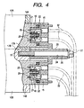
- Fig. 4 is a partially sectional side view of the connection structure.
- Fig. 5 is a perspective view of an example implemented by omitting one of the electronic control units of the connection structure.
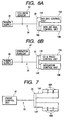
- Fig. 6A and 6B are block views of examples of a circuit to which the connection structure is applied.
- Fig. 7 is a schematic view of another example of application of the connection structure.
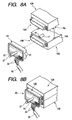
- Fig. 8A and 8B are perspective views of examples of modification of the connection structures.
- Fig. 9 is a block view of an example of a conventional wiring arrangement applied to electric devices.
- a structure described hereinbelow is used for connecting a common wire harness 30 shown in Fig. 2 and such like to two electronic control units (electronic devices) 10A, 10B shown in Fig. 1 and such like.
- This structure has a single case 12 and configured so that both the two electronic control units 10A and 10B are accommodated and held in this case 12.
- Each of the electronic control units 10A and 10B has a substrate case for storing a control substrate.
- An outside shape of the case is a nearly rectangular flat box, as illustrated in the figure.
- Concave grooves 10a extending in a frontward and rearward directions are formed in both lateral side surfaces of the electronic control unit 10A, respectively.
- a device-side connector 14A connected to the internal control substrate is fixed on a front surface of the control unit 10A.
- concave grooves 10b extending in a frontward and rearward directions are formed in both lateral side surfaces of the electronic control unit 10B, respectively.
- a device-side connector 14B connected to the internal control substrate is fixed on a front surface of the control unit 10B.
- the case 12 is shaped in such a way as to be opened to a front thereof.
- two ridges namely, upper and lower ridges 12a and 12b are formed.
- the electronic control units 10A and 10B are inserted and slid from the front into upper and lower portions of the case 12, respectively, so that these ridges 12a and 12b are fitted into the concave grooves 10a and 10b, respectively.
- both the electronic control units 10A and 10B are held at the upper and lower positions in the case 12, respectively.
- the device-side connectors 14A and 14B provided on the electronic control units 10A and 10B, respectively, are arranged in upward and downward directions.
- a recess portion 17A is formed in a central part of a bottom portion of the case for the upper electronic control unit 10A.
- a convex portion 17B which can be fitted into the recess portion 17A, is formed in a central part of a top portion of the case for the lower electronic control unit 10B. Even when the convex portion 17B is fitted into the recess portion 17A, a relative position in a direction of width of each of the electronic control units 10A and 10B is fixed. Further, in the convex portion 17B, a screw hole 18 opened to the front is formed.
- a hood 15 opened to the front is formed on each of the housing of the device-side connectors 14A and 14B. Many male terminals 16 are provided on an inside of this hood 15.
- a harness-side connector (a wire-component-side connector) 20 which can be coupled to both the device-side connectors 14A and 14B, is provided at a terminal of the wire harness 30.
- a pair of upper and lower fitting convex portions (coupling portions) 21 are formed to be integral with the housing of the harness-side connector 20.
- Each of the fitting convex portions 21 is formed to be able to be fitted into each of the hoods 15 provided on the device-side connectors 14A and 14B.
- the fitting convex portion 21, which can be fitted into each of the hoods 15, is integrally formed therewith as a single connector housing.
- a location of the fitting convex portions 21 coincide with that of the device-side connectors 14A and 14B in a state in which both the electronic control units 10A and 10B are held in the case 12, respectively.
- a terminal accommodating chamber is formed in each of the fitting convex portions 21.
- Female terminals 22 shown in Fig. 4 are fixed in the each terminal accommodating chambers. These female terminals 22 are fixed at terminals of the electric wires 32 included in the wire harness 30. Moreover, male terminals 16 of the device-side connectors 10A and 10B are fitted into these female terminals 22.
- flexible lances 29 shown in Fig. 4 are formed in each of the terminal accommodating chambers of the fitting convex portions 21, flexible lances 29 shown in Fig. 4 are formed.
- retainers 25 shown in this figure is attached to each of these fitting convex portions 21 from the front side (namely, the left-hand side in Fig. 4). Thus, the lances 29 are cramped and take such a shape to catch the female terminals 22, respectively.
- a bolt insertion cylinder portion 23 shaped to pass through the harness-side connector 20 in an axial direction is formed at a central position (namely, the position between both the fitting convex portions 21) of the harness-side connector 20.
- This bolt insertion cylinder portion 23 constitutes a bolt insertion hole 24, through which a bolt 26 can pass through.
- the bolt 26 comprises a head portion 27 having a modified cross-section and being able to be rotated by using a tool.
- a tip end portion at an opposite side of the bolt 26 can be screwed into the screw hole 18 of the electronic control unit 10B.
- the common wire harness 30 is easily connected to both the electronic control units 10A and 10B according to, for example, the following procedure.
- the electronic control unit 10A is slid and inserted into the upper step of the case 12 while fitting the concave grooves 10a of the electronic control unit 10A into the ridges 12a of the case 12, respectively.
- the electronic control unit 10B is slid and inserted into the lower step of the case 12 while fitting the concave grooves 10b of the electronic control unit 10B and the recess portion 17A into the ridges 12b of the case 12 and the convex portion 17B of electronic control unit 10B, respectively.
- the screw hole 18 is placed between both the device-side connectors 14A and 14b (shown in Fig. 3).
- both the electronic control units 10A and 10B may be simultaneously inserted into the case 12 by preliminarily fitting the convex portion 17B into the recess portion 17A.
- the male terminals 16 of the first-device-side connectors 14A and 14B are gradually fitted into the female terminals 22 of the harness-side connector 20. Finally, the first-device-side connectors 14A and 14B and the harness-side connector 20 are securely tightened together.
- both the device-side connectors 14A and 14B are coupled together to the single harness-side connector 20, whereby the common wire harness 30 can be simultaneously connected to the two electronic control units 10A and 10B. Consequently, the wire harness 30 can be simultaneously connected to the two electronic control units 10A and 10B with efficiency by performing a connector coupling operation only once without increasing the number of necessary connectors and branching the wire harness 30 into many branch lines.
- a lower opening of the case 12 is blocked by using, for instance, a dummy plate 11 shown in Fig. 1.
- a harness-side connector 20' which can be coupled only to the device-side connector 14A and has an ordinary constitution (see Fig. 5), is provided at the terminal of the wire harness 30. Consequently, the structure according to this embodiment can easily deal with this situation. Therefore, an alteration of vehicle-mounted devices, which is associated with the upgrading of the vehicle, is easily dealt with, and the general versatility is enhanced.
- Fig. 6 illustrates practical examples of the above described.
- an air bag control unit corresponds to the electronic control unit 10A
- a side air bag control unit corresponds to the electronic control unit 10B.
- These control units are connected to a power supply 40 and a collision sensor 42 through the wire harness 30.
- the circuit of this example is configured according to ordinary specifications, it is sufficient that only the air bag control unit serving as the electronic control unit 10A is attached to the case 12 and that the wire harness 30 is connected only to the device-side connector 14A as shown in Fig. 5.
- the side air bag control unit serving as the electronic control unit 10B is attached to the case 12 in addition to the air bag control unit, as shown in Figs. 2 to 4, and that the wire harness 20 is simultaneously coupled to both the device-side connectors 14A and 14B of the electronic control units 10A and 10B.
- the CD-and-radio control unit corresponds to the electronic control unit 10A and the navigation device control unit corresponds to the electronic control unit 10B.
- These control units are connected to the power supply 40 and the operating portion 44, such as a center cluster module, through the wire harness 30.
- the circuit of this example is configured according to ordinary specifications, it is sufficient that only the CD-and-radio control unit serving as the electronic control unit 10A is attached to the case 12 as shown in Fig. 5, and that the wire harness 30 is connected only to the device-side connector 14A.
- the navigation device control unit serving as the electronic control unit 10B is attached to the case 12 in addition to the CD-and-radio control unit, as shown in Figs. 2 to 4, and that the wire harness 20 is simultaneously coupled to both the device-side connectors 14A and 14B of the electronic control units 10A and 10B.
- the wire harness 30 can be connected to both the units 10A and 10B by maintaining the simple configuration of the circuit. Furthermore, the centralized management of all of such connections at a single place can be realized. Additionally, the maintenance of the circuit is easily achieved.
- an object connected to the electric wire component is not limited to the electronic control unit.
- the present invention has wide applicability to the case that the common wire component is connected to a plurality of electronic devices.
- each of the device-side connectors 14A and 14B may be a distributing connector shown in Fig. 7.
- the device-side connectors 14A and 14B illustrated in the figures are incorporated into, for instance, a cylinder head of an engine.
- a plurality of electromagnetic control valves namely, valves for controlling intake and exhaust valves for a left cylinder of the engine
- 48A disposed on the left-hand side of the engine
- a plurality of electromagnetic control valves namely, valves for controlling intake and exhaust valves for a right cylinder of the engine
- 48B disposed on the right-hand side of the engine are connected to the other 14B of the device-side connectors.
- an engine control unit 46 can be connected to both the device-side connectors 14A and 14B through this harness-side connector 20 and the wire harness 30. Moreover, a control signal can be transmitted from the engine control unit 46 to the electromagnetic control valves 48A and 48B through the device-side connectors 14A and 14B.
- an engaging portion (corresponding to the positioning portion) for fixing the relative position of each electronic device may be provided therein.
- an engaging projection lOc is provided in one 10A of the electronic control units.
- An engaging recess portion 10d is provided in the other electronic control unit 10B.
- Both the electronic control units 10A and 10B may be adapted to be positioned at the normal relative positions, respectively, by engaging the engaging projection 10c with the engaging recess portion 10d (namely, the locations of the fitting convex portions 21 of the harness-side connector 20 coincide with the location of a corresponding one of the device-side connectors 14A and 14B, respectively).
- the "electric wire component” is not limited to the wire harness 30.
- the “electric wire component” may be a single cable that includes a plurality of wires.
- the bolt 27 When the magnitude of the necessary fitting force of the connector is relatively small, the bolt 27 can be omitted. Even when this bolt 27 is used, the tightening position thereof can be suitably set.
- the convex portion 17B for positioning the device is provided in one of the electronic devices (namely, the electronic control unit 10B in the situation illustrated in Fig. 1), as described above, the screw hole 18 for screwing the bolt is provided in the convex portion 17B.
- a sufficient space for forming the screw hole 18 can be secured by effectively utilizing the convex portion 17B without increasing the size of the electronic device.
- this screw hole 18 and the bolt insertion hole 24 of the harness-side connector 20 are provided at places between both the connectors 14A and 14B (namely, between the fitting convex portions 21).
- a bolt tightening force can be uniformly exerted on both device-side connectors, so that the well-balanced coupling is realized.
- the actual number and arrangement of the electronic devices and the device-side connectors are not limited.
- three or more electronic devices and device-side connectors may be arranged in upward and downward directions or in lateral directions.
- four or more electronic devices and device-side connectors can be arranged in longitudinal and transversal directions.
- the device-side connectors 14A and 14B are male connectors having male terminals 16 and in which the harness-side connector 20 is a female connector having the female terminal 22.
- the device-side connectors may be such female ones, while the harness-side connector may be such a male connector.
- a plurality of hoods are formed in the harness-side connector 20 in such a way as to be integral therewith. Further, the housing of each of the device-side connectors is fitted into a corresponding one of the hoods.
- the wire-component-side connector provided at the terminal of the wire component is simultaneously coupled to the plurality of device-side connectors provided on the plurality of electronic devices, respectively.
- the present invention has advantages in that the number of necessary connectors is prevented from increasing, and that the common connection of the electric wire component to the electronic components can be efficiently achieved at little expense in time and effort by employing a simple configuration in which the number of branch lines branched from the wire harness is limited.
Landscapes
- Details Of Connecting Devices For Male And Female Coupling (AREA)
- Connector Housings Or Holding Contact Members (AREA)
- Coupling Device And Connection With Printed Circuit (AREA)
Applications Claiming Priority (2)
| Application Number | Priority Date | Filing Date | Title |
|---|---|---|---|
| JP32942499A JP2001148267A (ja) | 1999-11-19 | 1999-11-19 | 電子機器接続用コネクタ及びその接続構造 |
| JP32942499 | 1999-11-19 |
Publications (1)
| Publication Number | Publication Date |
|---|---|
| EP1102363A1 true EP1102363A1 (fr) | 2001-05-23 |
Family
ID=18221246
Family Applications (1)
| Application Number | Title | Priority Date | Filing Date |
|---|---|---|---|
| EP00125035A Withdrawn EP1102363A1 (fr) | 1999-11-19 | 2000-11-16 | Connecteur pour appareil électronique et structure de connexion pour connecter avec |
Country Status (3)
| Country | Link |
|---|---|
| US (1) | US6619995B1 (fr) |
| EP (1) | EP1102363A1 (fr) |
| JP (1) | JP2001148267A (fr) |
Cited By (2)
| Publication number | Priority date | Publication date | Assignee | Title |
|---|---|---|---|---|
| CN105390863A (zh) * | 2015-11-16 | 2016-03-09 | 宁波公牛电器有限公司 | 一种墙壁暗装的电气装置 |
| EP3669428B1 (fr) * | 2017-08-17 | 2022-03-02 | Harting Electric GmbH & Co. KG | Modules de connecteurs verrouillables |
Families Citing this family (18)
| Publication number | Priority date | Publication date | Assignee | Title |
|---|---|---|---|---|
| US6902430B2 (en) * | 2002-06-13 | 2005-06-07 | Ge Medical Systems Global Technology Company, Llc | Connector housing retainer |
| US7004795B2 (en) * | 2003-08-07 | 2006-02-28 | Anderson Power Products | Powerpole connector assembly and methods thereof |
| JP4539383B2 (ja) * | 2005-03-14 | 2010-09-08 | トヨタ自動車株式会社 | 動力伝達装置のコントロールユニット取付構造 |
| JP5047538B2 (ja) * | 2006-05-12 | 2012-10-10 | 矢崎総業株式会社 | ワイヤハーネスの接続構造 |
| JP4034330B1 (ja) * | 2006-09-20 | 2008-01-16 | タイコエレクトロニクスアンプ株式会社 | 回路ユニット収容ボックス |
| USD573536S1 (en) | 2007-04-17 | 2008-07-22 | Traxxas Lp | Electrical connector |
| US7374460B1 (en) | 2007-04-17 | 2008-05-20 | Traxxas Lp | Electrical connector assembly |
| USD576557S1 (en) | 2007-04-17 | 2008-09-09 | Traxxas Lp | Electrical connector |
| KR100938848B1 (ko) * | 2008-04-29 | 2010-01-27 | 주식회사 가포아이엔지 | 안마기용 호스의 접속 및 분배장치 |
| WO2011054031A1 (fr) | 2009-11-03 | 2011-05-12 | Orica Explosives Technology Pty Ltd | Connecteur et procédés d'utilisation associés |
| DE102010034520A1 (de) * | 2010-08-16 | 2012-02-16 | Gm Global Technology Operations Llc (N.D.Ges.D. Staates Delaware) | Träger für ein Steuergerät eines Kraftfahrzeuges, Steuergerät und Kraftfahrzeug |
| US9847630B1 (en) * | 2017-02-09 | 2017-12-19 | Sumitomo Wiring Systems, Ltd. | Locking and retaining structure for attaching fuse box to battery tray |
| KR102373471B1 (ko) | 2018-06-29 | 2022-03-10 | 주식회사 엘지에너지솔루션 | 확장형 커넥터 조립체 |
| USD939442S1 (en) | 2020-03-16 | 2021-12-28 | Traxxas Lp | Electrical connector for a model vehicle |
| USD933014S1 (en) | 2020-03-16 | 2021-10-12 | Traxxas Lp | Electrical connector for a model vehicle |
| US11569589B2 (en) | 2020-04-07 | 2023-01-31 | Traxxas, L.P. | Electrical power tap connector |
| USD1054383S1 (en) | 2022-09-07 | 2024-12-17 | Traxxas, L.P. | Electrical connector |
| USD1054382S1 (en) | 2022-09-07 | 2024-12-17 | Traxxas, L.P. | Electrical connector |
Citations (7)
| Publication number | Priority date | Publication date | Assignee | Title |
|---|---|---|---|---|
| US5057971A (en) * | 1988-03-08 | 1991-10-15 | Mannesmann Kienzle Gmbh | Modular stockable housing for electronic device |
| US5274570A (en) * | 1989-05-22 | 1993-12-28 | Mazda Motor Corporation | Integrated circuit having metal substrate |
| US5336109A (en) * | 1993-04-15 | 1994-08-09 | The Whitaker Corporation | Stacked connector assembly |
| US5431573A (en) * | 1992-10-28 | 1995-07-11 | Yazaki Corporation | Connector usable with a low intensity of insert power |
| FR2720594A1 (fr) * | 1994-05-27 | 1995-12-01 | Siemens Automotive Sa | Boîtier électronique. |
| US5529426A (en) * | 1991-10-24 | 1996-06-25 | Yazaki Corporation | Housing block-retaining construction |
| US5564953A (en) * | 1993-09-17 | 1996-10-15 | Yazaki Corporation | Divided-type multi-pole connector |
Family Cites Families (5)
| Publication number | Priority date | Publication date | Assignee | Title |
|---|---|---|---|---|
| US3447036A (en) * | 1967-04-21 | 1969-05-27 | Bell Telephone Labor Inc | Assembly for mounting and aligning modules |
| JP2613985B2 (ja) * | 1991-05-21 | 1997-05-28 | 矢崎総業株式会社 | ねじ締めコネクタ |
| JP3145271B2 (ja) * | 1995-05-16 | 2001-03-12 | 矢崎総業株式会社 | 低挿入力コネクタ |
| JP3138219B2 (ja) * | 1996-09-03 | 2001-02-26 | 矢崎総業株式会社 | コネクタ |
| US6179653B1 (en) * | 2000-03-23 | 2001-01-30 | Simula Co. Ltd. | Stacking computer connector |
-
1999
- 1999-11-19 JP JP32942499A patent/JP2001148267A/ja active Pending
-
2000
- 2000-11-15 US US09/712,299 patent/US6619995B1/en not_active Expired - Fee Related
- 2000-11-16 EP EP00125035A patent/EP1102363A1/fr not_active Withdrawn
Patent Citations (7)
| Publication number | Priority date | Publication date | Assignee | Title |
|---|---|---|---|---|
| US5057971A (en) * | 1988-03-08 | 1991-10-15 | Mannesmann Kienzle Gmbh | Modular stockable housing for electronic device |
| US5274570A (en) * | 1989-05-22 | 1993-12-28 | Mazda Motor Corporation | Integrated circuit having metal substrate |
| US5529426A (en) * | 1991-10-24 | 1996-06-25 | Yazaki Corporation | Housing block-retaining construction |
| US5431573A (en) * | 1992-10-28 | 1995-07-11 | Yazaki Corporation | Connector usable with a low intensity of insert power |
| US5336109A (en) * | 1993-04-15 | 1994-08-09 | The Whitaker Corporation | Stacked connector assembly |
| US5564953A (en) * | 1993-09-17 | 1996-10-15 | Yazaki Corporation | Divided-type multi-pole connector |
| FR2720594A1 (fr) * | 1994-05-27 | 1995-12-01 | Siemens Automotive Sa | Boîtier électronique. |
Cited By (3)
| Publication number | Priority date | Publication date | Assignee | Title |
|---|---|---|---|---|
| CN105390863A (zh) * | 2015-11-16 | 2016-03-09 | 宁波公牛电器有限公司 | 一种墙壁暗装的电气装置 |
| CN105390863B (zh) * | 2015-11-16 | 2018-01-19 | 宁波公牛电器有限公司 | 一种墙壁暗装的电气装置 |
| EP3669428B1 (fr) * | 2017-08-17 | 2022-03-02 | Harting Electric GmbH & Co. KG | Modules de connecteurs verrouillables |
Also Published As
| Publication number | Publication date |
|---|---|
| US6619995B1 (en) | 2003-09-16 |
| JP2001148267A (ja) | 2001-05-29 |
Similar Documents
| Publication | Publication Date | Title |
|---|---|---|
| US6619995B1 (en) | Electronic device connector and connection structure for use within a vehicular environment | |
| US7499262B1 (en) | Power distribution bus bar | |
| US6077102A (en) | Top down electrical distribution center assembly | |
| US20060046557A1 (en) | Connector restraint device | |
| US20080032565A1 (en) | Power terminal block | |
| JP5360967B2 (ja) | Ecuシステム | |
| US20020025718A1 (en) | Bulkhead connector system including angled adapter | |
| US5944534A (en) | Functional module | |
| US20030017727A1 (en) | Junction box | |
| US4929182A (en) | Mounting construction for on-vehicle electrical connection apparatus | |
| JP3414597B2 (ja) | 接続端子の固定構造 | |
| US5713757A (en) | Assembly for supplying power | |
| CN112242626B (zh) | 具有拉力释放装置的插接连接件 | |
| KR200243895Y1 (ko) | 단자대 모듈의 접지 구조 | |
| US7147521B2 (en) | Wiring junction block | |
| JPH087972A (ja) | 分割多極コネクタ | |
| JP3094144B2 (ja) | ロック構造及びロック解除用治具及びロック解除方法 | |
| JPH10247451A (ja) | ネジ締め型ヒュージブルリンクを備えた電気接続箱 | |
| US20210031710A1 (en) | Power supply apparatus | |
| JPH11299115A (ja) | 車両用バッテリボックス | |
| JP2000092649A (ja) | プロテクタ | |
| JP3168898B2 (ja) | ブロックおよびそれを用いた電線付き端子の保持具 | |
| JPH0590844U (ja) | ボルト締めコネクタ | |
| KR100700048B1 (ko) | 고전압 케이블용 접지브라켓의 고정구조 | |
| JPH10284177A (ja) | 電気接続構造 |
Legal Events
| Date | Code | Title | Description |
|---|---|---|---|
| PUAI | Public reference made under article 153(3) epc to a published international application that has entered the european phase |
Free format text: ORIGINAL CODE: 0009012 |
|
| AK | Designated contracting states |
Kind code of ref document: A1 Designated state(s): DE FR GB |
|
| AX | Request for extension of the european patent |
Free format text: AL;LT;LV;MK;RO;SI |
|
| 17P | Request for examination filed |
Effective date: 20010704 |
|
| AKX | Designation fees paid |
Free format text: DE FR GB |
|
| GRAH | Despatch of communication of intention to grant a patent |
Free format text: ORIGINAL CODE: EPIDOS IGRA |
|
| STAA | Information on the status of an ep patent application or granted ep patent |
Free format text: STATUS: THE APPLICATION IS DEEMED TO BE WITHDRAWN |
|
| 18D | Application deemed to be withdrawn |
Effective date: 20030219 |